1
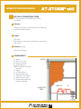
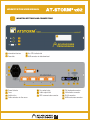
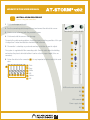
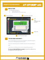
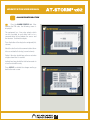
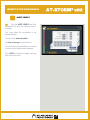
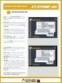
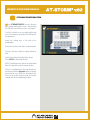
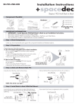
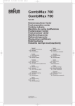
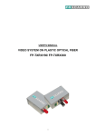
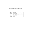
WORKSTATION USER MANUAL 2011 LIGHTNING PROTECTION DIVISION WORKSTATION USER MANUAL Introduction Menu Options Alarm configuration Alert levels System operation Storage configuration Data access trough the network Free-Contact Relays 3 9 10 11 13 14 WORKSTATION USER MANUAL INTRODUCTION This handbook explains briefly the different configurations which can be implemented with the ATSTORM v.02 Workstation. For more detailed information, contact Aplicaciones Tecnológicas, S.A.: APLICACIONES TECNOLÓGICAS, S.A. Parque Tecnológico de Valencia. C/ Nicolás Copérnico, 4. 46980 Paterna (Valencia). ESPAÑA (SPAIN) Tfno: (+34) 96 131 82 50 Fax: (+34) 96 131 82 06 [email protected] www.at3w.com WORKSTATION USER MANUAL INSTALLATION INSTRUCTIONS For the installation of ATSTORM 3 parts will be considered: Sensor: Always placed outdoors and over the roof. Provided with a multicore female connector. Cable: 25m cable. Male multicore connector at one extreme (for connecting with sensor). Station(interface). Always placed indoors. COMPONENTS 1 Sensor 2 Mast 1 1 ½’’, 1,5m 4 Screws M4x10mm 2 Anchorage pieces 25 M. Connection cable with 1 connector 1 Station 1 LCD touchscreen 1 Schucko power cable 1 VGA cable screen-station 1 USB touchscreen cable 1 Screw monitor power with Schucko connection SENSOR CONNECTION CABLE MONITOR PC WORKSTATION USER MANUAL MONITOR SETTINGS AND CONNECTIONS 1 2 3 4 1 Information interface 2 Power leds 3 Use CPU indicator led 4 USB connector for data download 1 4 2 6 7 9 10 3 5 1 Power Schucko 2 Fuses 3 Switch of/on 4 Cable connector for the sensor 5 5 Dry contact relay 6 Audio output Jack 7 DB9 communicaton conector 8 11 8 PS2 keyboard connector 9 VGA monitor connector 10 RJ-45 connector 11 USB touchscreen connector WORKSTATION USER MANUAL INSTALLACION PROCEDURE Sensor: fixing and connections 1 Fix the anchorages on the wall. 2 Pass the connecting cable through the mast and connect the cable to the sensor. 3 Fix the sensor to the mast with the provided 4 screws Cable connection Sensor connection 4 Fix the mast with the sensor in the achorage. The part of the cable running outdoors should be placed inside the guard tube. If this part is longer than 1 meter then that tube should be fixed to the wall. a 5 The monitor is a desktop so you do not need any installation or special subject. The system is supplied with 25m connecting cable. Once the cable enters the building and reaches the place to be installed then it can be cut to the proper length (it has no connector). 6 Fasten the cables in the connector 55 It is very important to follow carefully the code color a 5 a b c d e f Pink b Grey c White d NC e Yellow f NC b c d e f USB touchscreen connection a N/C b N/C c VGA connector d Power supply Jack e N/C ff WORKSTATION USER MANUAL MENU OPTIONS The Workstation has two parts: 1) Touchscreen for easy use. 2) Interface between the sensor and the screen. Alarm level indicator Present Electric field value Date Time Temperature inside the sensor Relay status Electric field evolution graphic Touchscreen components: Scroll of leds that lights up according to the existing electric field and the configured alarm levels, thus indicating the present storm hazard. Colour LCD screen that displays the information sent by the sensor, represented on a graph. Labels to access the different menus in order to configure different parameters. To access any label the PIN code is needed. The default PIN is 0000 and it can be changed in the SYSTEM CONFIG screen WORKSTATION USER MANUAL ALARM CONFIGURATION Press the ALARM CONFIG label. After entering the PIN code, the following screen is displayed: The equipment has 4 free relay outputs which can be associated to each alarm level or to a communication failure between the sensor and the interface. To define the outputs: Press the button of the relay to be configured (first column) Select the alert level or the communication failure to be associated to that relay (second column). Define if the relay should keep active or not when a higher alarm level is reached. Indicate how long should the field value remain in a level to activate the relay Press APPLY to validate the changes and to go back to the main screen. WORKSTATION USER MANUAL ALERT LEVELS Press the ALERT LEVELS label. After entering the PIN code, the following screen is displayed: This screen allows the configuration of two different elements: The value of the alarm threshold. The time of storage for each alert level. Press the button of the parameter to be fixed and insert the value using the numeric keyboard. Press APPLY to validate the changes and to go back to the main screen. WORKSTATION USER MANUAL System configuration Press on the SYSTEM CONFIG label. After entering the PIN code, the following screen is displayed: Device ID: Allows introducing the ID number of the equipment. Then it will be registered in the network as ATSTORM + ID. The system will be rebooted. IP Assign: Pressing on the DHCP label, the IP configuration will be automatically assigned if the network allows it. If not, the user should enter manually the IP, the subnet mask, the gateway and the DNS server. New PIN/Confirm PIN: it is necessary to confirm the PIN code every time it is changed. Press on the NEXT button to access the second configuration window. Time Scale: Select the time for the graphic representation of the field evolution. Possible values: 1, 4, 12 or 24 hours. Max. Field: Insert the highest field value in V/m to be represented on the field evolution graph. Data Source: There are 2 options: Internal: to connect the equipment directly to the sensor. Network: to contact a workstation that is connected to the network through a computer using the specific ATSTORM software. When this option is chosen, two new fields will appear in order to introduce the IP address and the port of the remote equipment to be connected. Date/Time: changing the date and time of the equipment. Press APPLY to validate the changes and to go back to the main screen. WORKSTATION USER MANUAL STORAGE CONFIGURATION Press STORAGE CONFIG. to access the main data storage configuration screen. After entering the PIN code, the following screen is displayed: From this screen the user can download the data into a flash memory connected to the USB port of the equipment: Select the starting date of the data to be downloaded. Select the last date of the data to be downloaded. Choose if the data should be copied, deleted or both. Select the unit where the data will be stored. Press APPLY to download the data. NOTE: Depending on the amount of downloaded data, this operation may take several minutes. If there is an updated file in the main directory of the memory, then the Upgrade button will appear every time the user selects the destination unit. Press on this button and the system will reboot, starting with the new updated application. WORKSTATION USER MANUAL Data access trough the network It is possible to access the data trough the network: • Insert either the name of the equipment or its IP address in a PC explorer connected to the same network: \\ATSORM0001 or \\192.168.0.70 • Write the User: Atstorm • Write the Password: the PIN code configured on the equipment. • The equipment shares two folders: a) Data contains the *.csv files with the data storage. b) Logs contains the log files with the most important events. data file example The system creates daily a .csv file named with the date (yyyymmdd.csv). The number of different data per day will depend on the time of storage for each alert level that is selected in the menu of ALERT LEVELS. An example of a data file may be as follows: FREE-CONTACT OUTPUTS The Workstation is equipped with four freecontact outputs that can be configured in the ALARM CONFIG. menu. Those outputs are four relays with two contacts: one normally open and the other normally closed. They will commute according to the given configuration. The connections are as follows: Hour Type of sensor Field value Type of sensor Temperature value 00:02:07,1,-203,2,268 00:03:07,1,-257,2,268 00:04:07,1,-620,2,268 00:05:07,1,-994,2,268 00:06:07,1,-839,2,268 00:07:07,1,-786,2,268 1 Normally open 2 Common 3 Normally closed Vmax: 250 Vac Imax: 2A WORKSTATION USER MANUAL Technical Specifications ATSTORM®v2 Operating Detection range 10 km around the sensor Resolution 1V/m Response time 1 second Sensor measuring range -100 to +100 KV/m Interface display Touchscreen Alarm levels 4 configurable alarm levels Interface alarm sound level 80 dB Electrical Sensor DC Voltage 15Vdc Interface power supply 230Vac (+/-15%) Frequency 50Hz Power 15 W Relay outputs 4 configurable outputs (for instance 3 storm alarms and one communication failure 250Vac, 2A (block connector) Protections The interface is protected against overcurrents and overvoltagesa Mechanical SENSOR Weight 1 Kg Dimensions Ø166 x 226 mm Cable 25m Maximum separation distance 100m (with optional wire) Framework material Polypropylene IP Code IP54 Fixing Fixed to 1 ½” tube INTERFACE Weight 4,6 Kg Touchscreen weight 3,5 Kg Dimensions 350 x 260 x 120 mm Touchscreen dimension 12,1” WORKSTATION USER MANUAL AT-STORM®v.02 Technical Specifications Environmental Sensor working temperature -40 a 85ºC Interface working temperature -10 a 85ºC Communications Interface Configurable serial, Ethernet Outputs Audio signal Mounting Mast* 1½’’, 2m galvanised steel mast included Anchoring* U-shaped anchorage consisting of 2 galvanised steel, 30cm long supports with screws for wall fixing (all included) Corrugated tube Protection tube for communication cable included www.at3w.com