1
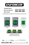
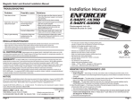
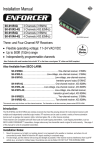
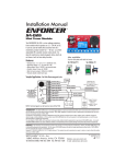
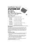
16/32 Channel 1U Rack Mount
CCTV Power Supply
Manual
PH-A3224-GUQ Shown
PTC
Glass Fuse
16-Channel
32-Channel
PH-A1612-PUQ
PH-A1612-GUQ
PH-A3224-PUQ
PH-A3224-GUQ
Industrial design
12 Amp at 24VAC
3 Amps per channel
Field-selectable 24/28 VAC
Easy cable management
Dual-color LED status indicators
For rack mounting, wall
mounting, and stacking
Note: Model number that end with “Q” or that have a round green “Q” sticker signify RoHS-compliant products.
ENFORCER RACKMOUNT POWER SUPPLY
Table of Contents:
Introduction .........................................................2
Features..............................................................2
Installation Notes ................................................2
Parts List .............................................................3
Specifications......................................................3
Installation........................................................3-6
Sample Application .............................................7
Overview .............................................................7
Troubleshooting ..................................................8
Also Available .....................................................8
Safety Warnings..................................................8
Warranty .............................................................8
Introduction:
ENFORCER PH-A Series Rack Mount CCTV Power Supplies are the ideal way to simplify and
consolidate your CCTV power supply system into one convenient package. These power
supplies fit into standard 19” IT racks to integrate smoothly into your existing rack mount setup.
The units provide flexible power, mounting, and cable management options to best suit your
CCTV power needs in an attractive, compact package.
Features:
Compact 1U height fits into standard 19” equipment racks.
Field-selectable power output — 24VAC, 28VAC, or OFF (selectable in sets of 4 channels).
Dual-color LED status indicator for each output:
Blue
Normal
Red
Fuse tripped
Off
Channel off
Front panel opens with no tools necessary for easy access to fuses. (Glass fuse models only.)
Note: Included front panel lock tab can be installed for greater safety and security.
Flexible mounting options:
a. Rack mount: Mount facing forward (easy access to indicator LEDs) or backward (easy access to connections).
b. Wall mount: Brackets face down for easy attachment on walls, under tables, etc.
c. Desk & Shelf mounting: Units can be stacked together or with other equipment.
Flexible cable management options:
a. 2 cable management brackets with 3 different mounting points.
b. 2 cable management hooks with 3 different mounting points.
Removable screw terminal blocks for convenient installation and reliable connections.
Overheat-protected power transformer(s) with thermal fuse.
Glass fuse and PTC models available in either 16- or 32-channel formats.
Attractive, high-tech industrial design.
Installation Notes:
1.
2.
3.
4.
5.
2
DOUBLE-CHECK AC OUTPUT VOLTAGE BEFORE CONNECTING CAMERAS.
FOR INDOOR USE ONLY. Do not install the unit outdoors or expose it to rain or moisture.
For professional installation and use only. Installation must conform to all local codes.
Avoid installing the unit near heat-generating or heat-sensitive equipment.
To prevent shock, do not open the housing. There are no user serviceable parts inside.
SECO-LARM U.S.A., Inc.
ENFORCER RACKMOUNT POWER SUPPLY
Parts List:
Rack mount power supply ........................................................................................................... 1x
Cable management brackets ...................................................................................................... 2x
Cable management hooks ........................................................................................................... 2x
M3x6 Cable bracket screws ......................................................................................................... 4x
Mounting brackets:
16-channel models (rack/wall/surface mount) .................................................................................... 2x
32-channel models (wall and surface mount only) ............................................................................... 4x
Extra-long rack mount brackets (32-channel models only) .................................................................. 2x
Rubber feet .................................................................................................................................. 4x
Power cord .................................................................................................................................. 1x
Front panel lock tab (Glass Fuse models only) ................................................................................... 1x
Spare fuses (PH-A1612-GUQ only, mounted inside unit, see Installation: Section D) ..................................... 3x
Spare fuses (PH-A3224-GUQ only, mounted inside unit, see Installation: Section D) ..................................... 6x
Spare main fuse (Mounted inside unit, see Installation: Section C) .......................................................... 1x
Manual ......................................................................................................................................... 1x
Specifications:
Fuse type
Input voltage
Number of outputs
PH-A1612-PUQ
PTC1
Total supply current
Max. amps per ch.
Rack size
Dimensions
Weight
1Positive
Temperature Coefficient
PH-A1612-GUQ PH-A3224-PUQ
Glass
PTC1
120VAC2
16
12A@24VAC max.
10A@28VAC max.
PH-A3224-GUQ
Glass
32
24A@24VAC max.
20A@28VAC max.
3A@24VAC max.
1U 19" (44.5x483 mm)
13/4"x171/2"x1113/32" (45x445x290 mm)
14-lb 14-oz (6.75kg)
22-lb 10-oz (10.25kg)
2220VAC
also available. Please contact SECO-LARM.
Installation:
A. Mounting
1. Decide on a location to install the unit, away from moisture, high humidity, heat sources, etc.
2. Make sure there is enough space around the unit so air can flow in and out for cooling
purposes.
3. Be sure ventilation holes are not blocked by other equipment, rack housing, walls, etc.
4. To avoid undesirable operation in either the product or other equipment place the unit at
least 12” (30cm) from any television monitor or other radiation-producing, radiation-sensitive
or heat-producing equipment such as heaters, radiators, etc.
A1. Shelf/table mounting
1. Units may be stacked one on top of the other, or with other equipment.
2. Make sure the rubber feet are firmly attached to the bottom of the unit as shown in Figure 10
in the Overview section on page 7, and that no ventilation holes are blocked.
SECO-LARM U.S.A., Inc.
3
ENFORCER RACKMOUNT POWER SUPPLY
A2. Wall mounting (For 32-channel, see A4)
Figure 1
Middle mounting point
Bracket facing down
1. Remove the mounting screws from the middle
mounting points as shown in Figure 1.
2. Screw the left and right mounting brackets on, Mounting bracket
facing downward as shown in Figure 1.
3. Make sure no ventilation holes are blocked
when the unit is in place.
4. Use screws or bolts (not included) to mount the unit in the desired location.
Note: Make sure that the screws/bolts and mounting surface can support the weight of the unit.
A3. Rack mounting (For 32-channel, see A4)
1. Forward facing installation (for easy view of LED indicators):
a. Remove the mounting screws from the mounting points at the front of the unit.
b. Screw the mounting brackets onto the front of the unit as shown in Figure 2 or Figure 10.
2. Backward facing installation (for easy access to terminal blocks and ON/OFF switch):
a. Remove the mounting screws from the mounting points at the back of the unit.
b. Screw the mounting brackets onto the back of the unit as shown in Figure 2 or Figure 10.
3. Find an appropriate unused 1U space in the equipment rack and screw the unit in place.
4. Leave at least 0.5U above and below the unit for ventilation.
Note: No rear support rails are needed. The unit can be fully supported using the mounting
brackets provided.
Figure 2
Power supply mounted facing backward
Equipment rack vertical supports
Mounting screws (not included)
Mounting brackets mounted front/back
Power supply mounted facing forward
A4. 32-Channel model
1. Wall mounting:
a. 32-channel models have 4 wall mounting
brackets, one for each corner.
b. Attach the brackets, facing downward, at
the mounting points on the sides of the
unit as in Figure 3 on the right.
2. Rack mounting: (Caution: Do not use the
wall-mounting brackets for rack mounting)
a. Mount with the 2 extra-long brackets as
shown in Figure 4 on the right.
b. Attach each bracket at both the middle
and either front or rear mounting points.
4
Front mounting point
Rear mounting point
Figure 3
Front or rear
mounting point
Figure 4
Extra long mounting bracket
Middle mounting point
SECO-LARM U.S.A., Inc.
ENFORCER RACKMOUNT POWER SUPPLY
B. Wiring
1.
2.
3.
4.
5.
Unplug terminal blocks from their sockets for easy installation.
Connect equipment power input cables to the screw terminals side by side in N/P pairs.
Screw the terminals closed. Once done, reinsert the terminal block back into its slot.
Select channel voltage for each terminal block with the switches on the back of the unit.
For each group of channels, select either 24VAC or 28VAC. Switch unused channels to OFF.
Tech Tip: Group cameras with similar power-cable lengths on the same terminal block and set
the 24/28 VAC switch to compensate for voltage drops. Test voltage after changing settings.
Caution: Do not set 28VAC unless voltage drops under 21.5VAC to avoid camera
damage, etc.
6. Connect the unit’s power cord to a 120V outlet and switch on the unit.
7. Front-panel LEDs for channels set to 24 or 28 VAC should glow blue to show output is on.
8. Test the output at the camera end of each power cable to be sure voltage is correct.
Caution: Always test output voltage before connecting cameras or other equipment.
9. For cable management, see page 6. For example applications, see page 7.
C. Replacing the Main Fuse
USE ONLY WITH A 250V FUSE
Caution: Replace only with same
Figure 5
fuse type and rating.
Fuse holder
1. Find the main fuse at the back of
the unit, between the power cord
socket and the ON/OFF switch, as
Lever fuse holder
here
show in Figure 5 on the right.
2. To check or replace the fuse, first power the unit and remove the power cord.
3. Use a flat-head screwdriver to gently lever the fuse holder out at the place shown in Figure 5.
Be careful not to damage the soft plastic fuse holder with the screwdriver.
Tech Tip: There is a spare fuse in the top of the fuse holder—use the old fuse to push it out.
D. Replacing the Channel Fuses (Glass Fuse Models Only)
Note: PTC fuses automatically resets when current overload is fixed or removed.
1. Check if the front panel lock tab has been installed.
2. If so, remove it following the instructions in the section Using the Front Panel Lock Tab below.
3. Press on the front panel at the place marked “Push” on the upper middle of the panel.
4. The panel will click open and swing downward.
5. Each unit is equipped with spare fuses: 3 for 16-channel models; 6 for 32-channel models.
6. The spares are found in white fuse holders mounted conveniently on the circuit board.
Caution: Use caution when replacing fuses in order to avoid shocks or shorts.
E. Using the Front Panel Lock Tab (Glass Fuse Models Only)
1. Use the front panel lock tab when greater safety or security is needed.
2. The lock tab prevents the front panel from being opened accidentally or by unauthorized persons.
SECO-LARM U.S.A., Inc.
5
ENFORCER RACKMOUNT POWER SUPPLY
E1. Locking Tab, front position
Figure 6
1. Install the front panel lock tab
using the screw from the power
supply front mounting point as
shown in Figure 6 to the right.
2. To open: Loosen the screw and
slide the lock tab toward the right
to let the front panel open.
Front panel
Mounting bracket
3
1
Front panel lock tab
3
2
Rack mount screw
3. To close: Slide the lock tab toward the left over the front panel and tighten the screw.
Note: When loosening the rack mount screw, it may be necessary to support the rear of the unit.
E2. Locking tab, side positions
1. Install the front panel lock tab
using the screw from the power
supply front mounting point as
shown in Figure 7 on the right.
2. To open: Loosen the screw
and rotate the lock tab upward
to let the front panel open.
Figure 7
Front panel
Mounting screw
31
Front panel lock tab
32
Front right mounting point
3. To close: Rotate the lock tab downward so that it covers the front panel and tighten the screw.
Tech Tip: If the front panel lock tab falls off while opening, replace it starting with the tab
pointing up, and turn it down over the front panel.
F. Cable Management
1. There are two cable management options included with the product:
a. Cable management “G” brackets (x2). Screw the brackets onto any of the three mounting
points on the rear of the unit with the included M3x6 screws. Mount the brackets open end
at the top, as shown in Figure 8 below or Figure 11 on page 7.
b. Cable management hooks (x2). Press the white plastic hooks into any of the three mounting
holes on the rear of the unit as shown in Figure 8 below or Figure 11 on page 7.
Note: Cable management hooks, once inserted, cannot be removed.
2. Mount the brackets and route power cables in a way that best suits your installation. Be sure to
leave slack in the cable to ease future maintenance. Use cable ties to reduce cable tension.
See example in Figure 8 below.
Cable management bracket
Cable management hook
Figure 8
Use cable ties to secure cables
to cable management bracket
6
To cameras
Three mounting points
marked A, B and C
SECO-LARM U.S.A., Inc.
ENFORCER RACKMOUNT POWER SUPPLY
Sample Application:
Figure 9
DC Cameras, Accessories, etc.
Rack Mount Power Supply
Use ENFORCER
Voltage Converters
to supply your DC
equipment
ST-LA110-TTQ
ENFORCER Voltage Convertor
Overview:
A: Front mounting point
Figure 10
Mounting brackets
Power supply front panel
B: Center mounting point
Rubber foot & mounting point
Channel indicator LEDs
Figure 11
Power supply rear panel
Main fuse socket
Cable management hook
Terminal blocks
Cable management bracket
Power cord socket
SECO-LARM U.S.A., Inc.
Main power switch
24VAC/28VAC/OFF switches
7
ENFORCER RACKMOUNT POWER SUPPLY
Troubleshooting:
Power does not turn on
Check front panel LEDs and rear main fuse.
Ensure the power cord is firmly in its socket.
The unit may be overheating. Check for heat
sources nearby and ensure ventilation holes are
free from obstruction.
Use 18 gauge or thicker wire.
Check that the correct power is being supplied.
Power cycles on and off
Voltage drop is large
The camera case is hot
Also Available:
Rack Mount Active
Balun Hub
EVT-AH16-VT2Q
Cut cost and complexity
by sending CCTV signals
over Cat5e/6 cables up to
8,000ft (2.4km).
12VDC Tester with
Continuity
ST-BT02Q
Perform 6 different tests
including voltage drop,
voltage with load,
polarity, and continuity
(LED only).
Passive VPD Balun
1.0 Amp Voltage
Converter
EVT-PB1-31RQ
Transmit video, power,
and data signals over a
single Cat5e/6 cable up
to 2,000’ (610m).
ST-LA110-TTQ
Converts 8~30 VAC/VDC
to a regulated 5/12/24
VDC output (adjustable).
CAUTION: To reduce the risk of electric shock, do
not open the product case. There are no user
serviceable parts inside. Refer servicing to qualified
service personnel.
Glass fuse models only: During replacement of
fuses, access fuses via unit front panel only. Use
caution when working with live electronic
equipment.
WARRANTY: This SECO-LARM product is warranted against defects in material and workmanship while used in normal
service for a period of one (1) year from the date of sale to the original consumer customer. SECO-LARM’s obligation is
limited to the repair or replacement of any defective part if the unit is returned, transportation prepaid, to SECO-LARM.
This Warranty is void if damage is caused by or attributed to acts of God, physical or electrical misuse or abuse, neglect,
repair, or alteration, improper or abnormal usage, or faulty installation, or if for any other reason SECO-LARM determines
that such equipment is not operating properly as a result of causes other than defects in material and workmanship. The
sole obligation of SECO-LARM, and the purchaser’s exclusive remedy, shall be limited to replacement or repair only, at
SECO-LARM’s option. In no event shall SECO-LARM be liable for any special, collateral, incidental, or consequential
personal or property damages of any kind to the purchaser or anyone else.
NOTICE: The information and specifications printed in this manual are current at the time of publication. However, the
SECO-LARM policy is one of continual development and improvement. For this reason, SECO-LARM reserves the right
to change specifications without notice. SECO-LARM is also not responsible for misprints or typographical errors.
Copyright © 2010 SECO-LARM U.S.A., Inc. All rights reserved. This material may not be reproduced or copied, in whole
or in part, without the written permission of SECO-LARM.
®
SECO-LARM U.S.A., Inc.
16842 Millikan Avenue, Irvine, CA 92606
Tel: 800-662-0800 / 949-261-2999 Fax: 949-261-7326
8
Website: www.seco-larm.com
E-mail: [email protected]
PITSW1
mi-PH-AXXXX-XUQ_0911.docx
Order Part # 764-504%
SECO-LARM U.S.A., Inc.