1
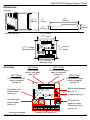
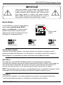
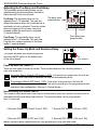
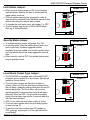
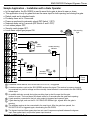
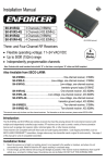
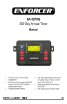
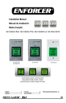
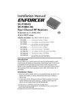
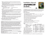
SA-025EQ Delayed Egress Timer Manual 3 Relock modes Programmable nuisance delay timer Adjustable pre-delay timer Adjustable post-delay timer 12~24VAC/VDC Form C relay outputs for lock relay and remote alarm Transistor ground output for local alarm outputs Auto or programmed relocking after power loss IMPORTANT Users and installers of this product are responsible for ensuring that the installation and configuration of this product complies with all national, state, and local laws and codes related to locking and egress devices. SECO-LARM will not be held responsible for the use of this product in violation of any current laws or codes. NOTE: Products with model numbers that end with “Q” or have a round green “Q” sticker signify RoHS-compliant products. ENFORCER Delayed Egress Timer Table of Contents: Features ........................................................ 2 Specifications ................................................ 2 Dimensions.................................................... 3 Overview ....................................................... 3 Installation ..................................................... 4 Wiring Diagram.............................................. 4 Relock Modes................................................ 5 Adjusting the Pre-Delay and Post-Delay ....... 6 Setting the Power-Up Mode and Nuisance Delay ............................................. 6 Lock Status Jumper....................................... 7 Security Mode Jumper .................................. 7 Local Alarm Output Type Jumper.................. 7 Remote Alarm Relay Output ......................... 8 Lock Relay Output ........................................ 8 Local Alarm Output ....................................... 8 Pre-Delay Bypass Input ................................ 8 Free Egress Input ......................................... 9 Reset Input.................................................... 9 Initiate Input .................................................. 9 Bypass Input ................................................. 9 Lock Status Input .......................................... 9 Power Input ................................................... 9 Sample Applications .............................. 10-11 Troubleshooting .......................................... 12 Warranty ..................................................... 12 Features: 3 Relock modes to meet different installation requirements: Standard manual relocking. BOCA (Building Officials Code Administrators) relocking. Timed relocking (1~60 seconds). Programmable nuisance delay timer (0~3 seconds). Adjustable pre-delay timer (1~30 seconds). Adjustable post-delay timer (1~60 seconds). Selectable manual or automatic relocking after power loss. Lock relay output (Form C, 10A@24VDC). Remote alarm relay output (Form C, 10A@24VDC). Local alarm output (transistor ground, 500mA@12VDC). Door status input. Status LEDs show relay status. Bypass input immediately releases locks. Free egress input allows easy egress during the day. Specifications: Operating voltage 12~24 VAC/VDC 120mA@12VDC 90mA@12VDC Current draw 35mA@12VDC 15mA@12VDC Lock control output 10A@24VDC, Form C, NO/NC/COM Remote alarm output 10A@24VDC, Form C, NO/NC/COM Local alarm output Transistor ground, 500mA@12VDC 1Lock relay and remote alarm relay are normally energized. 2When lock relay and remote alarm relay are de-energized. Standby1 Pre-delay Local alarm Timer module only2 2 SECO-LARM U.S.A., Inc. ENFORCER Delayed Egress Timer Dimensions: Housing 211/16” (68mm) 3 1 /4 ” (83mm) 3” (76mm) 1 1 /8 ” (28mm) 7 /8 ” (22mm) Timer module only 21/2” (63mm) P.C. board 31/16” (78mm) P.C. board 213/16” (72mm) Mounting holes 21/4” (57mm) Mounting holes Overview: LED 1 (Blue): If ON, the SA-025EQ is being powered (see pg. 9) LED 2 (Red): If ON, the lock relay is energized* (see pg. 8) LED 3 (Red): If ON, the remote alarm relay is energized* (see pg. 8) LED 4 (Red): If ON, the local alarm is being triggered (see pg. 8) Post-delay timer potentiometer (see pg. 6) Relock mode jumpers (see pg. 5) Pre-delay timer potentiometer (see pg. 6) DIP Switch for Power-up mode & Nuisance delay (see pg. 6) *Normally energized. SECO-LARM U.S.A., Inc Jumpers (see pg. 7) Terminal block (see pg. 4) 3 ENFORCER Delayed Egress Timer Installation: Removing the housing To remove the housing cover from the SA-025EQ, use a paper clip or a similar object to push one of the two tabs on the back of the unit inward. Push tab inward. Mounting If mounting is necessary, secure two screws (not included) through the two screw holes located on the side of the unit to a mounting surface. Wiring Diagram: Remote alarm relay output (10A@24VDC, Form C Relay, NO/NC/COM)* (see pg. 8) Lock relay output (10A@24VDC, Form C Relay, NO/NC/COM)* (see pg. 8) Local alarm output (500mA@12VDC, transistor ground) (see pg. 8) Pre-delay bypass input (N.O.+) (see pg. 8) Free egress input (N.C.+) (see pg. 9) Reset input (N.C.+) (see pg. 9) Initiate input (N.C.+) (for unlock device) (see pg. 9) Bypass input (N.C.+) (see pg. 9) Lock status input (N.C.+) (see pg. 9) Power input (12~24 VAC/VDC) (see pg. 9) *Normally energized. (Screen print refers to energized state as normal.) 4 SECO-LARM U.S.A., Inc. ENFORCER Delayed Egress Timer IMPORTANT Users and installers of this product are responsible for ensuring that the installation and configuration of this product complies with all national, state, and local laws and codes related to locking and egress devices. SECO-LARM will not be held responsible for the use of this product in violation of any current laws or codes. Relock Modes: The SA-025EQ can operate in three different relock modes: standard mode, BOCA mode, and timed mode. In order to switch between these modes, locate the relock mode jumper on the circuit board and move the jumper to the appropriate pins. Standard mode Relock mode jumper BOCA mode Timed mode Standard Mode (Default) Once the lock has been released, it will remain released until manually relocked by a reset device connected to the Reset Input. For information on connecting a reset device, see pg. 4, Wiring Diagram. This reset device is often a momentary spring-loaded key switch. BOCA Mode This mode is for use with BOCA (Building Officials Code Administrators) regulations. Once the lock is released, the door will remain unlocked until the door is closed. Once closed, the door will still remain unlocked for 30 seconds. If the door is opened at any time during the 30 seconds, the timer will reset. The 30-second timer will restart once the door is closed. NOTE: The lock status jumper (see pg. 7) must be ON with a door-mounted N.C. magnetic contact connected to the lock status input terminal for the BOCA mode to operate correctly. Timed Mode Once the lock is released, it will remain released for the duration of the set post-delay timer. To set the post-delay timer see pg. 6, Adjusting the Pre-Delay and Post-Delay. SECO-LARM U.S.A., Inc 5 ENFORCER Delayed Egress Timer Adjusting the Pre-Delay and Post-Delay: The pre-delay and post-delay timers can be adjusted using the potentiometers located on the bottom left of the circuit board. Pre-Delay: The pre-delay timer can be adjusted from 1~30 seconds. This sets the delay time between when the initiate device is used and the lock is released. Once the initiate device is triggered, the process cannot be stopped unless the reset input is activated (1-second default). Pre-delay timer potentiometer Post-delay timer potentiometer Post-Delay: The post-delay timer can be adjusted from 1~60 seconds. This sets how long the door remains unlocked in the timer mode (1-second default). Setting the Power-Up Mode and Nuisance Delay: The power-up mode and nuisance delay are set using the DIP switch at the bottom right of the circuit board. DIP Switch Power-Up Mode (DIP Switch 1) There are two types of power-up modes. These modes determine the relocking status in case of a power loss. Automatic Relock (Default, DIP Switch 1 OFF): In the event of a power loss, the lock will release. When the power is restored, the lock will automatically relock. Programmed Relock (DIP Switch 1 ON): In the event of a power loss, the lock will release. When power is restored, the lock will relock according to the programmed mode and relock time configuration. (See pg. 5, Relock Modes.) Nuisance Delay (DIP Switch 2 and 3) The nuisance delay determines how long the initiate device (such as a push-to-exit bar) must be activated before the pre-delay timer will start. The nuisance delay can be programmed from 0~3 seconds. 0 Seconds (Default, DIP Switch 2 and 3 OFF) 1 Second (DIP Switch 2 ON and 3 OFF) 2 Seconds (DIP Switch 2 OFF and 3 ON) 3 Seconds (DIP Switch 2 ON and 3 ON) NOTE: Nuisance delay requirements will vary depending on local laws and codes. 6 SECO-LARM U.S.A., Inc. ENFORCER Delayed Egress Timer Lock Status Jumper: When the lock status jumper is ON, the lock status input will detect whether the door is closed and will trigger relock functions. The lock status input may be bypassed in order to keep the door unlocked for an indefinite period of time without activating the remote alarm output. To bypass the lock status input, set jumper 1 to OFF. The lock status input must be ON for BOCA Mode (See pg. 5, Relock Modes). Security Mode Jumper: To activate security mode, set jumper 2 to ON. In security mode, after the initiate device (such as a push-to-exit bar) has been triggered and the pre-delay timer has ended, the lock will remain active until the initiate device has been triggered a second time. When security mode is OFF, the initiate device must only be activated once. Local Alarm Output Type Jumper: The SA-025EQ is equipped with a 500mA@12VDC transistor ground output for a local alarm, typically an audible or visual device. The local alarm output can be set for steady or pulsing. When set ON, the local alarm pulses during the pre-delay, gradually pulsing faster until the end of the pre-delay time. The local alarm will continue signaling steady 5 seconds after the lock has been released. When set OFF, the local alarm is steady during the pre-delay time and for 5 seconds after the lock has been released. LED 4 is on when the local alarm output is active. The local alarm signals when the pre-delay bypass is used (see pg. 9). To set the local alarm output type ON (steady) or OFF (pulsing), use jumper 3 on the right side of the circuit board. SECO-LARM U.S.A., Inc Default: OFF Jumper 1 Default: OFF Jumper 2 Default: OFF Jumper 3 7 ENFORCER Delayed Egress Timer Remote Alarm Relay Output: The SA-025EQ is equipped with a 10A@24VDC Form C dry relay output for a remote alarm. The remote alarm relay is normally energized. The onboard screen print refers to the energized state as normal. A remote alarm connected to this output will begin signaling at the start of the pre-delay timer. The remote alarm will continue signaling until the door is relocked. In the event of power loss, the remote alarm relay will de-energize to trigger the remote alarm. The remote alarm will signal when the pre-delay bypass is activated. The remote alarm will also signal during free egress if the door is left open longer than 5 seconds (door status jumper must be ON for this to occur). LED 3 (red) is on when the remote alarm relay is energized. Lock Relay Output: The SA-025EQ is equipped with a 10A@24VDC Form C dry relay output that can be used with a fail-safe or fail-secure lock. The lock relay is normally energized. The onboard screen print refers to the energized state as normal. In standard mode, the lock relay will de-energize after the pre-delay time expires. The lock relay will re-energize when the reset input is activated. In BOCA mode, the lock relay will de-energize after the pre-delay time expires. The lock relay will re-energize after a door with a N.C. magnetic contact attached to the lock status input has been closed for 30 consecutive seconds. In timed mode, the lock relay will de-energize after the pre-delay time expires. The lock relay will re-energize after the post-delay time expires. LED 2 (red) is on when the lock relay is energized. Local Alarm Output: The SA-025EQ is equipped with a 500mA@12VDC transistor ground output for a local alarm. The local alarm output can be set for steady or pulsing by changing jumper 3 (see pg. 7) LED 4 (red) is on when the local alarm output is active. Pre-Delay Bypass Input (N.O.+): 8 Connect a N.O. switch between the pre-delay bypass and the positive terminal. The pre-delay bypass input bypasses the pre-delay time for immediate egress. The remote alarm and local alarm outputs are still active when the pre-delay bypass is used. The door will relock according to the relock mode. SECO-LARM U.S.A., Inc. ENFORCER Delayed Egress Timer Free Egress Input (N.C.+): Connect a N.C. toggle switch between the free egress input and the positive terminal. The free egress input allows the lock to be put in the free egress mode. This bypasses any delays and alarms, allowing the initiate device to act as a simple egress device. In the free egress mode, the lock is released as soon as the initiate device is triggered. The door will relock after 5 seconds. This can be used in conjunction with a timer (such as the SA-027Q annual timer) to allow free egress during the day, but restricted access at night. The remote alarm will also signal during free egress if the door is left open longer than 5 seconds (the lock status jumper must be ON for this to occur). If not used then a jumper must be installed between the free egress input and the positive power input terminal. Reset Input (N.C.+): Connect a N.C. switch between the reset input and the positive terminal. The reset input is used to reset the SA-025EQ. The reset input is only necessary in the standard relock mode. Initiate Input (N.C.+): Connect a N.C. device (such as the SD-961A-36 Push-to-Exit Bar) between the initiate input and the positive terminal. The initiate input is used to activate the SA-025EQ. To activate, hold down the initiate input for the duration of the nuisance delay timer. Bypass Input (N.C.+): Connect a N.C. switch between the bypass input and the positive terminal. The bypass input is used to bypass the SA-025EQ and allow unrestricted entry and exit via the door. When the bypass input is activated, the lock will immediately release. It will remain released until the bypass input is deactivated. The bypass input will not trigger the remote alarm or local alarm. If not used then a jumper must be installed between the bypass input and the positive power input terminal. Lock Status Input (N.C.+): Connect a N.C. magnetic contact (such as the SM-200Q) between the lock status input and the positive terminal. The lock status input will detect if the door on which the magnetic contact is mounted is closed in order to trigger the relock functions. Power Input (12~24 VAC/VDC): The SA-025EQ is powered by a 12~24 VAC or VDC power supply. LED 1 (blue) is on when the SA-025EQ is powered. SECO-LARM U.S.A., Inc 9 ENFORCER Delayed Egress Timer Sample Application – Installation in a Building In this application, the SA-025EQ is used to delay exit from a building. Relock mode set to standard mode. Pre-delay timer set to 15 seconds. Power-up mode set to automatic relock (DIP Switch 1 OFF). Nuisance delay set to 0 seconds (DIP Switch 2 and 3 OFF). Lock status jumper ON. Security mode jumper OFF. Local alarm output type jumper ON. Strobe light Electromagnetic lock Alarm buzzer Spring-loaded switch Push-to-exit bar Magnetic contact Power supply 1. A N.C. magnetic contact mounted on a door is connected to the lock status input so the SA-025EQ knows if the door is opened or closed. 2. A push-to-exit bar is connected to the initiate input. This device will be the primary means of egress. 3. A spring-loaded switch is connected to the reset input. This device will manually reset the lock. 4. A spring-loaded switch is connected to the pre-delay bypass input. This will allow any authorized user immediate access to the protected premises. 5. An alarm buzzer is connected to the local alarm output to indicate when the SA-025EQ is in the process of unlocking a door. The alarm buzzer will remain active for 5 seconds after the door is unlocked. 6. An electromagnetic lock is connected to the lock relay output. 7. A strobe light is connected to the remote alarm relay output. This device will signal at a remote location whenever the remote alarm relay output is triggered. 8. The bypass input and free egress input are not used. Jumpers are placed between the bypass input, free egress input, and positive power input terminal. 10 SECO-LARM U.S.A., Inc. ENFORCER Delayed Egress Timer Sample Application – Installation with a Gate Operator In this application, the SA-025EQ is used to warn that a gate is about to open or close. This application is only for gates that use the same input for both opening and closing the gate. Relock mode set to standard mode. Pre-delay timer set to 15 seconds. Power-up mode set to automatic relock (DIP Switch 1 OFF). Nuisance delay set to 0 seconds (DIP Switch 2 and 3 OFF). Lock status jumper OFF. Security mode jumper OFF. Gate warning Local alarm output type jumper ON. light Gate operator Wireless receiver Audible warning indicator Wireless transmitter Power supply 1. A wireless initiate device, such as the SK-919TD1S-UP, is triggered. 2. A wireless receiver, such as the SK-910RBQ receives the signal. The receiver’s common terminal is connected to a positive voltage and the normally closed terminal is connected to the SA-025EQ’s initiate input. 3. An audible indicator sounds during the pre-delay time to alert the user that the gate is about to open. The local alarm will remain active for 5 seconds after the gate starts opening. 4. A gate operator connected to the lock relay output is triggered and opens a gate. 5. A gate warning light, such as the SL-1301-BAQ LED Strobe Light, signals while the gate is opening. 6. The wireless receiver is also connected to the reset input. After the gate has opened, the SK-919TD1S-UP is triggered again, deactivating the SA-025EQ. 7. The bypass input and free egress input are not used. Jumpers are placed between the bypass input, free egress input, and positive power input terminal. SECO-LARM U.S.A., Inc 11 ENFORCER Delayed Egress Timer Troubleshooting: Check the nuisance delay. See pg. 6, Nuisance Delay. Check the pre-delay timer. See pg. 6, Adjusting the Pre-Delay and Post-Delay. Check the security mode. See pg. 7, Security Mode Jumper. Initiate device (such as a push-to-exit bar) will not release the lock Door will not relock Check the relock mode. See pg. 5, Relock Modes. Check the bypass input. See pg. 8, Bypass Input. Door automatically relocks in BOCA mode. Check the lock status. See pg. 7, Lock Status Jumper. Also Available from SECO-LARM: Electromagnetic Locks Magnetic Contacts Spring-Loaded Switches LED Strobe Lights 1-sec to 365-day Timers IMPORTANT Users and installers of this product are responsible for ensuring this product complies with all national, state, and local laws, statutes, and codes related to locking and egress devices. SECO-LARM will not be held responsible for the use of this product in violation of any current laws, statutes, or codes. WARRANTY This SECO-LARM product is warranted against defects in material and workmanship while used in normal service for a period of one (1) year from the date of sale to the original consumer customer. SECO-LARM’s obligation is limited to the repair or replacement of any defective part if the unit is returned, transportation prepaid, to SECO-LARM. This Warranty is void if damage is caused by or attributed to acts of God, physical or electrical misuse or abuse, neglect, repair, or alteration, improper or abnormal usage, or faulty installation, or if for any other reason SECO-LARM determines that such equipment is not operating properly as a result of causes other than defects in material and workmanship. The sole obligation of SECO-LARM, and the purchaser’s exclusive remedy, shall be limited to replacement or repair only, at SECO-LARM’s option. In no event shall SECO-LARM be liable for any special, collateral, incidental, or consequential personal or property damages of any kind to the purchaser or anyone else. NOTICE The information and specifications printed in this manual are current at the time of publication. However, the SECO-LARM policy is one of continual development and improvement. For this reason, SECO-LARM reserves the right to change specifications without notice. SECO-LARM is also not responsible for misprints or typographical errors. Copyright © 2012 SECO-LARM U.S.A., Inc. All rights reserved. This material may not be reproduced or copied, in whole or in part, without the written permission of SECO-LARM. SECO-LARM U.S.A., Inc. 16842 Millikan Avenue, Irvine, CA 92606 Tel: 800-662-0800 / 949-261-2999 Fax: 949-261-7326 12 Made in Taiwan Website: www.seco-larm.com E-mail: [email protected] PITSW1 Order Part #763-021-3% MiSA-025EQZZ_1210.docx SECO-LARM U.S.A., Inc.