1
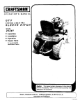
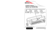
Owner's Manual
CULTIVATOR
MODEL:
CC-560
• Assembly
• Operation
• Repair Parts
For use with Garden Tractors. A Sleeve Hitch
Accessory is required for operation. Wheel
weights and chains are also recommended.
IMPORTANT
This manual contains information for the safety
of persons and property. Read it carefully before
assembly and operation of the equipment!
For the latest product updates and setup tips:
Visit us on the web!
www.brinly.com
1007076 Rev. A
INTRODUCTION
CONGRATULATIONS on the purchase of your new Brinly-Hardy
Cultivator! Your cultivator is designed, engineered and manufactured to
give you the best possible dependability and performance.
CUSTOMER RESPONSIBILITIES
Please read and retain this manual. The instructions enables you to
assemble and maintain your lawn aerator properly. And please, always
observe the “Safety” instructions.
TABLE OF CONTENTS
SAFETY/OPERATION/MAINTENANCE........................................ 2-3
PARTS BREAKDOWN ......................................................................4
ASSEMBLY.................................................................................... 5-7
WARRANTY ......................................................................................8
PRODUCT COMPATIBILITY
This cultivator is designed for use with garden tractors equipped with
a sleeve hitch. It may be used to cultivate a wide range of garden
vegetables or field crops. It can be set up for straddle-row and/or
between-row cultivation.
RECORD PURCHASE INFORMATION
Record your purchase information in the spaces provided below:
DATE OF PURCHASE:
COMPANY NAME:
COMPANY PHONE:
SERIAL NUMBER:
SAFETY/OPERATION/MAINTENANCE
SAFETY
TO HELP PREVENT BODILY INJURY DUE TO LOSS
OF STABILITY OR CONTROL:
Read the general safety operating precautions in your towing
vehicle operator's manual for additional safety information.
• Do not exceed maximum capacity of towing vehicle listed
in the vehicle operator's manual.
PROTECT BYSTANDERS
• Towing this machine behind a ZTR (Zero Turning Radius)
mower is not recommended due to the sharp turning ability
of the ZTR. Damage to this machine or the ZTR may result.
ZTR’s typically operate at higher speeds. Operating above 5
mph may result in damage to this machine.
1007076 Rev. A
• Keep bystanders away when you operate this machine.
• Before you back look carefully behind for bystanders.
• Before you operate any feature of this machine, observe
your surroundings and look for bystanders.
2
SAFETY/OPERATION/MAINTENANCE
OPERATE SAFELY
KEEP BODY PARTS FROM UNDER TOW BAR
• Use this machine for intended purpose only.
Before disconnecting this machine from towing vehicle hitch:
• Speed should always be slow enough to maintain control.
Travel slowly over rough ground.
• Stop on level ground.
• Stop towing vehicle engine.
• Lock towing vehicle park brake.
• Block wheels of the machine.
• Make sure body parts are not under tow bar.
• Do not let children or an untrained person operate
machine.
• Do not let anyone, especially children, ride on this machine
or the towing vehicle.
OPERATION
• Cultivate at a slow tractor speed.
• Check towing vehicle brake action before you operate.
Adjust or service brakes as necessary.
• Additional weight is not normally required for cultivating
light soil. However, it is necessary when soil is heavy,
crusted, and/or thickly weeded, in order to improve the
cultivator's penetration and stability.
• Keep all parts in good condition and properly installed. Fix
damaged parts immediately. Replace worn or broken parts.
Replace all worn or damaged safety and instruction decals.
• See Figure 6 for instructions on attaching concrete block
as additional weight.
• Do not modify the machine or safety devices. Unauthorized
modifications to the towing vehicle or machine may impair its
function and safety, and void the warranty.
• Cultivating depth can be controlled by use of the adjustable
Gauge Shoes (7).
• Keep all nuts, bolts and screws tight.
MAINTENANCE
• Excessive load can cause loss of traction and loss of
control on slopes. Reduce weight when operating on slopes.
• The key to years of trouble-free service is to keep your
Cultivator clean and dry.
• Use only approved sleeve hitches. Do not attach this
machine except at the approved hitch point.
• Never allow wet material to remain on Cultivator for
extended periods of time.
• Follow the manufacturer's recommendations for weight
limits for towed equipment and using on slopes. Use
counterweights, wheel weights, or chains as described in the
towing vehicle operator's manual.
• For rust on Gauge Shoes (7) and Spring Shanks (6) apply
a light coat of oil. For rust on rest of Cultivator, sand and
apply a light coat of enamel paint.
• Do not shift to neutral and coast downhill.
• Periodically check all fasteners for tightness.
KEEP RIDERS OFF TOWED ATTACHMENT
QUALITY CONTINUES WITH QUALITY SERVICE
• Keep riders off towed attachment.
We provide a process to remedy your questions or problems.
• Riders on an attachment are subject to injury, such as
being thrown off the attachment during sudden starts, stops
and turns.
Follow the steps below to get answers to any questions you
may have about your product, or to order replacement parts:
1. Refer to your attachment and machine operator manuals.
• Riders obstruct the operator's view, resulting in the
attachment being used in an unsafe manner.
2. In North America and Canada, call 1-877-728-8224 and
provide product serial number and model number.
• Keep riders off of tow bar.
3
1007076 Rev. A
PARTS BREAKDOWN
8
10
3
STOP
20
17
9
2
13
18 16
14
Installation Questions?
Missing Parts?
Replacement Parts?
DON’T GO BACK
TO THE STORE!
Please call Customer Service
Department Toll Free
877.728.8224 or
[email protected]
19
15
4
11
10
10
10
5
19
15
7
19
21
20
19
1
15
17
15
19
6
15
ITEM NO. DESCRIPTION
PART NO.
14
12
QTY.
ITEM NO. DESCRIPTION
PART NO.
QTY.
2
1
Brinly Decal
B-5922
1
13
Plow Bolt 7/16" x 1-3/4"
15M1428P
2
Hitch Bracket
C-362-10
1
14
Hex Nut 3/8"
30M1200P
3
3
Pull Bar
C-363-10
1
15
Hex Nut 1/2"
30M1600P
14
4
Frame Angle
1007075-10
2
16
Hex Nut 7/16"
30M1400P
2
5
Frame Tie Bar
C-365-10
2
17
Lockwasher 3/8"
40M1200P
3
6
Spring Shank
C-352-10
7
18
Lockwasher 7/16"
40M1400P
2
7
Gauge Shoe Half
C-367-10
4
19
Lockwasher 1/2"
40M1600P
14
8
Rod Tie-Down
C-368
1
20
Flat washer 3/8"
45M1313P
3
9
Tie Strap
C-369-10
1
21
Special Spacer
B-723P
7
10
Hex Bolt 1/2 x 1-1/2"
2M1624P
13
11
Hex Bolt 1/2" x 2"
2M1632P
1
12
Carriage Bolt 3/8" x 1"
11M1216P
2
1007076 Rev. A
4
ASSEMBLY
Figure 1
HITCH BRACKET AND TIE
STRAP ASSEMBLY
10
TOOLS REQUIRED:
3
9/16" Wrench (1)
3/4" Wrench (2)
11/16" Wrench (1)
9
13
2
18 16
15
1a. Loosely assemble Hitch Bracket
(2) to Pull Bar (3) using Plow Bolts (13),
7/16" Lockwashers (18), and 7/16" Nuts
(16) as shown. DO NOT TIGHTEN.
NOTE: It is important to orient Plow
Bolts in direction shown.
(13)
Plow Bolt, 7/16" x 1-3/4"
Qty. 2
19
(18)
Lockwasher, 7/16"
Qty. 2
(15)
Nut, 7/16"
Qty. 2
(19)
Lockwasher, 1/2"
Qty. 1
(15)
Nut, 1/2"
Qty. 1
1b. Assemble Tie Strap (9) to Pull Bar
(3) using 1/2" x 1-1/2" Bolts (10), 1/2"
Lockwashers (19), and 1/2" Nuts (15).
(10)
Bolt, 1/2" x 1-1/2"
Qty. 1
Figure 2
TIE STRAP/FRAME ANGLE
ASSEMBLY
4
2a. Assemble Frame Angles (4) to Tie Strap (9)
using 1/2" x 1-1/2" Bolts (10), 1/2" Lockwashers
(19), and 1/2" Nuts (15).
10
9
Snug but do not fully tighten at this time.
19
15
(10)
Bolt, 1/2" x 1-1/2"
Qty. 2
5
(19)
Lockwasher, 1/2"
Qty. 2
(15)
Nut, 1/2"
Qty. 2
1007076 Rev. A
ASSEMBLY
Figure 3
FRAME TIE BAR ASSEMBLY
4
3a. Assemble Tie Bars (5) to Frame Angles (4)
using 1/2" x 1-1/2" Bolts (10), 1/2" Lockwashers
(19), and 1/2" Nuts (15). 11
10
5
3b. Assemble Tie Bars (5) to Pull Bar (3) using
1/2" x 2" Bolt (11), 1/2" Lockwasher (19), and 1/2"
Nut (15).
3
19
15
19
3c. Tighten hardware from Step 2a.
(10)
Bolt, 1/2" x 1-1/2"
Qty. 2
Figure 4
15
(19)
Lockwasher, 1/2"
Qty. 3
(15)
Nut, 1/2"
Qty. 3
(11)
Bolt, 1/2" x 2"
Qty. 1
SPRING SHANK ASSEMBLY
4a. Assemble Spring Shanks (6) to Frame
Angles (4) using 1/2" x 1-1/2" Bolts (10), Special
Spacers (21), 1/2" Lockwashers (19), and 1/2"
Nuts (15). 5
A
4b. When assembling for in-between row
cultivation, the extra Spring Shank will be
mounted in the center of the cultivator, using
the same hole and hardware used to fasten Tie
Bars (5) to Pull Bar (3), reference location (A) in
illustration.
(10)
Bolt, 1/2" x 1-1/2"
Qty. 6
1007076 Rev. A
10
3
Ensure Spring Shanks are set to run straight in
the direction of travel.
4
21
19
15
(19)
Lockwasher, 1/2"
Qty. 6
(15)
Nut, 1/2"
Qty. 6
6
6
(21)
Special Spacer
Qty. 6 (or 7)
ASSEMBLY
Figure 5
GAUGE SHOE ASSEMBLY
5a. Assemble one of the Gauge Shoe
halves (7) to Frame Angle (4) using 1/2" x
1-1/2" Bolts (10), 1/2" Lockwashers (19),
and 1/2" Nuts (15). Note slot orientation in
illustration.
10
4
7
20
5b. Attach Gauge Shoe halves (7) together
using 3/8" x 1" Carriage Bolt (12), 3/8"
Washer (20), 3/8" Lockwasher (17), and
3/8" Nut (14).
(12)
Carriage Bolt, 3/8" x 1"
Qty. 2
Figure 6
14
19
15
(10)
Bolt, 1/2" x 1-1/2"
Qty. 2
17
(19)
Lockwasher, 1/2"
Qty. 2
(20)
Lockwasher, 3/8"
Qty. 2
12
(15)
Nut, 1/2"
Qty. 2
(17)
Flat Washer, 3/8"
Qty. 2
(14)
Nut, 3/8"
Qty. 2
MOUNTING ADJUSTMENT
6a. Attach Cultivator to your Tractor Hitch in lowered position.
6b. Adjust Hitch Bracket on Cultivator to obtain desired depth of
Cultivator.
6c. Cultivator should be parallel to ground. Adjust Plow Bolts (13) to
level Cultivator Shanks. Pull Bar (3) may be inverted to increase depth
of cultivation.
6d. Adjust Gauge Shoes (7) to maintain depth. Tighten all bolts
securely.
IMPORTANT
Cultivator must be stabilized to eliminate
"side to side" movement when cultivating crops. This is an
adjustment on the Sleeve Hitch, refer to Sleeve Hitch Manual for
instructions.
8
3
13
20
17
14
6e. If additional weight is needed (see page 3) concrete block should
be attached to the center of the Pull Bar (3) with the Rod Tie Down (8),
3/8" Plain Washer (20), 3/8" Lockwasher (17), and 3/8" Nut (14).
7
1007076 Rev. A
MANUFACTURER'S LIMITED WARRANTY FOR
Pull Behind Accessories
The limited warranty set forth below is given by Brinly-Hardy
Company with respect to new merchandise purchased and
used in the United States, its possessions and territories.
Brinly-Hardy Company warrants the products listed below
against defects in material and workmanship, and will at
its option, repair or replace, free of charge, any part found
to be defective in materials or workmanship. This limited
warranty shall only apply if this product has been assembled,
operated, and maintained in accordance with the Operator’s
manual furnished with the product, and has not been subject
to misuse, abuse, commercial use, neglect, accident,
improper maintenance, alteration, vandalism, theft, fire,
water, or damage because of other peril or natural disaster.
Normal Wear Parts or components thereof are subject
to separate terms as follows: All normal wear parts or
component failures will be covered on the product for a
period of 90 days.
Parts found to be defective within the warranty period will
be replaced at our expense. Our obligation under this
warranty is expressly limited to the replacement or repair,
at our option, of parts found to be defective in material and
workmanship.
HOW TO OBTAIN SERVICE: Warranty parts replacements
are available, ONLY WITH PROOF OF PURCHASE, through
our Pull Behind Accessories Customer Service Department.
Call 877-728-8224.
This limited warranty does not provide coverage in the
following cases:
• Routine maintenance items such as lubricants and filters.
• Normal deterioration of the exterior finish due to use or
exposure.
• Transportation and/or labor charges.
• The warranty does not include commercial and/or rental
use.
No implied warranty, including any implied warranty
of merchantability of fitness for a particular purpose,
applies after the applicable period of express written
warranty above as to the part as identified below.
No other express warranty whether written or oral,
except as mentioned above, given by any person or
entity, including a dealer or retailer, with respect to
any product, shall bind Brinly-Hardy Co. During the
period of the warranty, the exclusive remedy is repair or
replacement of the product as set forth above.
1007076 Rev. A
The provisions as set forth in this warranty provide
the sole and exclusive remedy arising from the sale.
Brinly-Hardy Co. shall not be liable for incidental or
consequential loss or damage including, without
limitation, expenses incurred for substitute or
replacement lawn care services or for rental expenses to
temporarily replace a warranted product.
Some states do not allow the exclusion or limitation of
incidental or consequential damages, or limitations on how
long an implied warranty lasts, so the above exclusions or
limitations may not apply to you.
During the warranty period, the exclusive remedy is
replacement of the part. In no event shall recovery of any
kind be greater that the amount of the purchase price of the
product sold. Alteration of safety features of the product shall
void this warranty. You assume the risk and liability for loss,
damage, or injury to you and your property and/or to others
and their property arising out of the misuse or inability to use
this product.
This limited warranty shall not extend to anyone other than
the original purchaser or to the person for whom it was
purchased as a gift.
HOW STATE LAW RELATES TO THIS WARRANTY: This
limited warranty gives you specific legal rights, and you may
also have other rights which vary from state to state.
IMPORTANT: The Warranty period stated below begins with
the PROOF OF PURCHASE. Without the proof of purchase,
the Warranty period begins from the date of manufacture
determined by the serial number manufacturing date.
CULTIVATOR WARRANTY PERIOD:
The warranty period for this cultivator is as follows: Frame
parts - 2 Years. Spring Shanks are normal wear items - 90
days.