1
OPERATOR'S
MANUAL
G TV
SPRING
ASSISTED
SLEEVE
HITCH
MODEL:
25241
• Assembly
• Installation
• Operation
• Repair Parts
For usewithSEARS
LawnlGardenTractors
This manual contains informationfor U]e
persons and property, Read it carefully before assembly and
operation of the equipment!
Sears, Roebuck and Co., Hoffman Estates, IL 60179 U.S.A.
www, sears.comlcraftsman
=
ill
CUSTOMER RESPONSIBILITY_
Clean and stem in waterproof building.
Apply a light coat of grease or oil to threaded parts, pivot points and the inside of HitchTube,
Touch up any scratches with enamel paint to avoid rusting.
TABLE OF CONTENTS
SAFETYRULES ..............................................................2
MAINTENANCE..............................................................."J
WARRANTY.................................................................i....2
HARDWARE.................................. ..................................3-4
PARTSREFERENCE ......................................................5
PARTSLIST .....................................................................5
ASSEMBLY......................................................................6-g
OPERATION....................................................................t0
NOTES .............................................................................
11
Limited
For two(2) years from.the
accoraing
to the operating
free
safetypnl_u_onstilto_lmut_Lsrnanual.It
rreans• ATT*ENTIONI
BECOME
ALERTIyoursafelyisinvolved.
,, ,i
ii
i
Warranty
date of purchase
when th. = SI.eeva Hitch is meints ned and ubr cate.d
ana maintenance
Instructions
In the uwners
ManuaJ, oeara will repair,
of charge, any defect in material or workmanship.
This warranty
does not cover:
Repairs necessar.y because of operator abuse or negll_lence including
equipment eccoromg to instructions
contained in _the uwner's
Manual;
commercial
or rental purposes.
WARRANTY
SERVICE
CENTERIDEPARTMENT
This warranty
i
the failure to maintain the
end Sleeve Hitch used for
IS AVAILABLE BY CONTA_T-ING
THE NEAREST SEARS SERVICE
N THE UNITED STAT, ES,, .Th s_w.arranty app es on y whe
th a product
IS in use in me unneo _tates.
gives you specific
legal rights, and you may also have other rights whiah vary from
state to stale.
SEARS, ROEBUCKAND
CO,, D/8t7 WA, Hoffman Estates, IL80179 EE.UU.
Congratulations
on yourpumhaealYourequipmenthasbeendesigned,engineered,and manufactured
to giveyouthe bestpossible
dependabilityend performance.
Should youexperienceany problemyou cannoteasilyremedy,pleasecontact.yournearestSeam ServiceCentarlDepsrtmsnt.We
havecompetent,well-trainedtechniciansend the propertoolsto =er_cp.or rap=atyourequipment.Pleasereadand retainthis
Owner'sManual. The instructions
willenableyouto assembleend mmntamyoureqmpmentpmpedy.Alwaysobservethe 'Safely
Rules'prior to use.
RULES FOR SAFE OPERATION
•
Knowcontrolsa_l howtostop towing equipmentq_.
RF.ADTHE OWNEN8 MANUAL
•
Do notallow Childrento upstate the vehicle,Do notallowedulinto odarabbwithoutproper inslzu,'_n orwithouthavingmad the
Owners Manual,
a Doeotcarryp_sensers, Keepddldmnendpet6soldedistaltcemvay,
• Alwayswearsubatanclalfootwee¢, De notw_r _
dcthlngIhstcan getcaughtIn movingpe_ts.
• Keepyoureyes and mindon yourtawingequlpment/ellechment
and aresbeinge=avered.
Do notletcther Jnteres_distractyou.
• Stayaldrtfarbolas in los te/TalnalKI o0tnrhiddenhazards.
• Do notdrivecloseto creaM, ditches, andpubli€hlghwmys.
• Watchoutfor traffi:whse cr_sll_ or near roadways.
a Whenusingany attachment,don'tallow any=qenearthe vehiclewhileIn operation.
a Keep_le vehicleendeltachment In good oberdug mndlbn andImepsaintydnvlm_in place.
• KeepeUnuts, bob, endscrewstightto be sum theequipmentIs In _
woddngcondition.
A
•
ThevehP.._endattac_lnlentshouldbe MoppedandIrlBpOcled
fordamageafter_king anyforeign objecLThe damageshould =e repaired
beforerosta_ng and oparalingthe eqt_nt.
•
See towing equipmentOwnsr'oManualtar safeoperationof the equlpmact.
MAINTENANCE
....
The keytoyears oftmubis..fmeserviceIsto kees yourEquipmentdean anddW.
Occasionally_o=k all movingp_t= for flee movementsnd, if necauwy, lubricatewithoiL.
Should rustdmmlop,Imnd I_hlly Ild UIsnp_l( m _
onanlel,
Psriodk_lly_heCkallfnstenemfor tlsntnems.
.
NARL)WAI_ REFERENCE
11
©
,. ©
24
(1)3e "x_.l,e" _1P/,
22
25
3, L*_S;'_ag
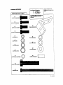
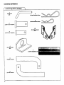
HARDWARE REFERENCE
i.i
ii
*
Hardware Bag (Part No. ;[-1258"4)
D
(t) HI_ Pin
NTS
8
I
(2)SmallR_mJnlng
Spring
2
(2) 5/rxI-1/2"
ClevIe /=in
(1) I12"x1-1/4"
ClevisPin
ol
10
I)nr_ar _e_t
NTS
4
(2) PIv_ Bracket
NTS
5
(1)Upper_JnLink
6
(t) Lowtr Lln/..Ink
,,.,,,,ll,i i
4.
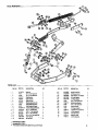
Parts Reference
Pans List
REF. NO.
PART NO.
Dc_:CRIP'rlON
QTY.
1
H-t 30P-01
H;tch Pin
1
2
14-522
_
x 1-1/2" Ck)vts Pin
2
3
V-21gP
1/2" x 1,-1/4" ChUB Pin
4
H_I
Pivot 8mckld
0
6
H-_27,,O'I
LOWm"Lift Lk_
7
H-528,,01
_a_w,Adjuzdmenl
a
H-S2e
_
g
H-S30
10
REF, NO.
PART NO,
DESCRIPTION
QTY
_' 17
31Mt2QQp
3/8" Hax JalrflbNUt
1
1
" 18
"_ 19
2
" 20
31M2OOOp r_" t.lex _arr_ N_t
40MtOOOp _ts', M_d{um L_ W_her
40MI200P
3/8 '__
Washer
'l
" 21
*' 22
45MI71?P
H-_
618_x 3" H_ Hend Bolt
2
H-_,10
H-70g
8_r_
1
3
4
9
Link
1
spm_
4
23
" 24
Sm_] RetJlning .,qp41_Q
2
*" 2_
H-763
Adjustment BOR
1
P,-532RL-10
D ra_lr
t"
" 2e
H-?e4
31_" HgW
3
_nlng
Brl_.keta (RP_H)
_
Bm_,
31if' X 1-1/1_ C_vJ_ pit1
_r
1
"
11
11M1216P
3/8- x 1" Carf_ip
1
27
H-584-10
UflA_t
*"
12
tMlO16P
rd1_ x 1" Hex Head Bort
,ll
28,
Lift Bar Ass_'nbly
--
t3
2MI_l_P
3_8"X I" HKK Haad B_
6
H-'721-10
N-78_-SR
Hi_l Bail w,'la_l
1
"
la
2M1220P
3/8" X 1-1/4" HeX Head BO_
2
_o
H-720-10
F..xl_r_lo_ Strap
2
"*
15
30M¶ POOP
6/If
Lt_ Affn Assembly
1
-
1_
30M1200P
3_" HBX Nut
R*'Jt
It_x Nut
4
'" :
Spnng Assetnbly
1
1
_" B '
_- "_lSbc,scket
ts_tvtdedir_ b¢opa_t|f_mdngn LH& RH!_l_
5.
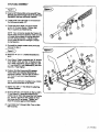
FRONTFRAME& LIFT
ASSEMBLY
Figure I.
Figure I,_
BEFORE PROCEEDINGlU
1. Mower Deck must be removed from Tractor.
2. Tractor HeightAdjustment Knob must be
lowered completely.
far as possible (see Fig. 1).
3. Lower the Lift Mechanism completely
(Mechanical or Electric).
4. Remove Plastic Accoss Cover (part # 121749X)
from the Left Side of Tractor Frame.(see Fig. 3)
r
I
I
.1
TRACTOR
REARENDWEW
5. Remove the Hex Bolt securing the top of the
Tractor Fuel Tank Bracket to the frame on the
left.hand side,
Rguro 2. ,,)
6. Install the Lift Assist Bracket(23) over the fuel
tank]orecket as shown. TheUltAss/stBrackat
assembles to the outside of the frame, with the
short/eg through the opening/n frame. Secure
using two 3/8°_xl" Hex Bolts(13-MUST BE
INSTALLED FROM INSIDE TO OUTSIDE),
Lock Washara(20), Hex Nuts(16), and a 3/8"
Washer(26) between the the Lift Assist Bracket
and the fuel tank bracket in the FORWARD
HOLE ONLY1 "r'_jhtenSecurely.
©
7. Make sure the fuel tank Hex Bolt previously
removed is tightened securely,
8. From the rear of the tremor, feed the LiftAssist
Spring(27- hook end first) along the inside left of
the Tractor frame, just below the fuel tank.
9. Locate the Tractor Lift Shaft Assembly.
! 0, Insert the the "hook-end" of the LiftAssist
Spring(27) into the 'T'-shaped hole in the Lift
Shaft Assembly as shown.
NOTE: LlftAssist Spring(27) and Bolt can be
easily accessed through Access opening at left
sicle of Tractor. Simply remove cover on frame
to access if not already removed from Step 4,
1I. As shown, secure the Lift Assist Spring(27) in
the top-right of the "T"-shaped hole using a
3/8"x1" Can'iage Bolt(11), 3/8" Washer(26),
Lock Washer(2g), and Hex Nut(16),
&
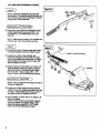
DETAIL
HITCH BAIL ASSEMBLY
Figure 4., ,_
12. Install a 3/8" Washer(26) on the long.3/8" Hex
Bott(25) and insert through hole in the Lift Assist
Bracket(23) that was previo_Jslyinstalled.
13. Thread a 3/8" Hex Jam Nut(17) on the end of
the Bolt approximately 112".
14, Thread the Bolt at least 1/2" into threaded
portion of Lift Assist Spring. Tighten Jam
Nut(17) against List Assist Spring.
NOTE: Have someone operate the Trectar Lift
Handle while someone checl_ to make sure the
Lift Assist Spring clears all moving parts and
fuel tank during opereUon. Failure to clear
moving parts wil| result in damage to Tractor
during operation.
J
15. Re-install the plastic access cover previously
removed in step 4.
Figure 5. _)
16. Break the "R" and "L" Drewber Brackets(lO)
apalt.
17. From Rear of Tractor, assemble the "R" Bracket
to the RIGHT SIDE, and the "L" Bracket to the
LEFT SIDE respeotively, secure using four 3/8"
x 1"Hex Bolts(13), Lock Washers(20), and Hex
Nuts(16). Fi_er tighten.
18. Position Hitch BailAssembly(29) between
Tractor frame and Dmwbar Brackets(10)
previously installed. Secure with two 5/8"xl1/2" Clevis Pins(2) and Large Retaining
Spring(8}.
NOTE: Long extension of welded tube of Hitch
Bail must be pesitioned UP as shown.
19. Tighten four 3/8" x 1" Hex Baits(13) attaching
Drawbar Brackets,
20. Screw a 5/8" Hex Jam Nut(18) on the two 5/8"x
3" Hex Bolts(2?.). Assemble these through
welded nuts on Hitch BailAssembly, from inside
out. Screw in until flush with outside of Hitch
Bail Assembly(29) as shown. Tighten Jam
Nuts(18) securely against Hitch Bail(2g).
2!. Insert Hitch Pin(l) through Hitch Tube in Hitch
BailAssembly.
7', L-1674-_R,00
LIFT BAR AND EXTENSION
STRAPS
,, ,,
f
,,, •
Figure
.. 6. )
Figure 6.
NOTE: Extension Straps(30) are used WIUl
Me_anical LiftTm_ors(havinglift handles) only
and wit_not be used when mounting to Tm_
using Electric LiftAccsesodse.
CMECHANICAL LIFT TRACTORS
22.,_ssemble the two Extension Straps(30) to the
Lift Bar Asesmbly(28) using two 3/8'_( %1/4"
He:<Bolts(14), Lock Washers(20), end Hex
Nu_s(16).
NOTE:, Make sure the holes in the opposite end
of Straps ere in line, then tighten securely.
Figure 7. )
.J
Figure
23.From RIGHT side of Tractor, locate the T_u_tor
Lift Shaft Assembly under the Tractor Frame.
Tractor Lift
Shaft Assembly
24. Position the Lift Bar Assembly(28), with
Extenston Straps(3g), along inskta of Tractor
Frame with welded end towards rear of Tractor,
Stide welded end through cutout in upper left
side of Omk_ar as shown.
25. Position Extension Straps(30) over Tractor Lift
Shaft Assembly Arm(at LEFT side of Tractor),
aligning end holes to Straps(30) with bottom
hole in Lift Arm. Secure using 3/8"x %1/8"
Clevis Pin(24), and Small Retaining Spring(g).
(.,ELECTRIC LIFT TRACTORS
)
NOTE: This mounting will not require the use of
Extension Straps(30),
26, Position the Lift Bar Assembly along inside of
Tractor Frame with welded end towards the rear
of Tractor. Slide welded end through cutout in
the upper left side of Drawber as shown.
27.NOT SHOWNI: .P|e-se refer to the Electric L|ft
Manual if needed,
Postion and of Uft BarAssembly(28) between
opening of Electric Lift double straps, Align
holes and secure using 3/8"x 1,-t/8" Clevis
Pin(24) and Small Retaining Spring(g).
\
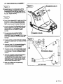
LIFT ARM/TURNBUCKLE
ASSEMBI-Y
F
Figure 8. ,_
Figure 8.
L
28. Assemble the first Pivot Bracket(4) with the
short leg towards the =enter of the Tractor
Drawbar and to the far left Side using two 5/16"
x 1" Hex Bolts(12), Lock Washers(19) and Hex
Nuts(15) "13ghtensecurely.
Figure 9.
29. Place LiftArm Assembly(31) inside hole of Pivot
Bracket(4) as shown in Ftg 9. Note that that
longer arm on the Pivot Brad_t will be to the
right or more towards the center of the tractor.
30 Assemble the other Pivot Brasket(4) with short
leg facing towards the left side of the Drawbar
using two 5/16" x 1" Hex Bolts(12), Lock
Washers(19) end Hex Nuts(15). "13ghten
securely.
31. ConneCt previously assembled Lift Bar
Assembly(2B) to short arm on Ltit Arm
Assembly(31) using ',_"diameter x 1-114"Clevis
Pin(3), Plain Washer(21 ), and small Retaining
Spring(9).
32.Thread a 5/8" Hex Jam Nut(18) onto the longer
right hand threaded Lower L.iff Link(6), as far as
possible.
33 Assemble Lower Lift LinkAseambly(6-step 32)
into the right hand threaded end of S_.eve
Adjustment Link('/')as far as possible.
34. Thread the shorter, (left hand threaded) upper
Lift Link(5) into other end of Sleeve Adjustment
Link(7)(screws in counter-clockwiea) as far as
possible.
Assemble in Step 2g.
35 Atl_ch the completed Tumbu_le Assembly to
the upper adjusting hole in the LiftArm
Assembly(31) and the welded tab in Hitch Ball
Assembly(29), Secure each end with a small
Retaining Spring(9). 11ghtanthe Jam Nut(18)
against Sleeve Adjustz1_entLink(7)_
36, Make sure all Bolts and Nuts previously
assembled are tight,
LEFT S/DE V/EW
9, L-1874_R.0O
ADJUSTMENTS
AlwaysmakeadjustmentswithAttachmentinstalled, priorto usingit,Add_onalAttachmentAdjustmentsmayalsobe
required.See theAttachmentInst_istlonManual.
STABILIZER ADJUSTMENT
Stabilizing an Attachment is removing all aide-to-side movemerd, Do Not Stabilize the Plow or Disk Hanow. Stabilize
all other Attachments.
s Turn both 5/8" x 3" Stabilizer Baits(22) clockwise and equally against Yoke of Att;achment.Lock the Stabilizer
Bolts in place with Hex Jam Nuts.
• Loosen Stabilizer Bolts to removaAttachmant from Hitch.
LIFT EFFORT ADJUSTMENT
The L_ Spring aids in liftingthe Attachment into Transport position. Due to different attachment weights, the Lift
Spring may require adjustments. The Adjusting Bolt (25, Fig 4) is located at the upper left side of Tractor Drewbar
Bracket.
• Lift effort is adjusted by increasing or reducing spdng tension on the lift assist spring(27).
" Do not adjust to maximum spring tension when using lighterweight attachments.
• Do not oveqaower spring when removing attachments.
• Always lock Tractor Lift Handle DOWN when removing attachments.
LIFT ASSIST SET-UP FOLLOWING
FOR AN ATTACHEMENT
(see Fig 2):
• Raise the Tractor Lift Handle to the Transport (up) position in order to adjust the Assist Spring tension.
i
Turn the Adjusting Bolt (25) CLOCKWISE until the Wa-=;her(26) is against the Lift Assist Bracket
oosen
thewill
flex
Jam Nut
(17) againSt
the Assist
Spring
(27).
(23),
This
reduce
lift effort.
Re-tighten
Hex Jam
I_lut(17).
Use the Hitch with Turnbuckle Link in the UPPER HOLE in LiftArm Assembly for most conditions. If Assist
Spring adjustment does not result in acceptable lift effort, move the TUrnbucklelink to the LOWER HOLE in
the Lift Arm Assembly,
TURNBUCKLE
ADJUSTMENT
(see Fig 11):
The Adjustable Turnbuckle can be lengthened or ehodened to controlTransport Height ofAttachment,
• Always adjust Tumbublde Assembly with Tractor Uft Handle locked in LOWERED position.
• At no time should the Turnbuckle Assembly be adjusted beyond 9-1/4" from end to end.
• Lower the Trecto_Lift Handle and lock into lowered position.You may need to lower the"
Attachment Depth Control"on your Tractor to do this,
, Mount the Attachment to the Sleeve Hitch using the Hitch Pin (1).
• With Attachment on ground, adjust Tumbuclde to give approximately 1" of distance between end of slot in Lift
Bar Assembly (28) and Clevis Pin (3) (see F_g.g) This will allow proper penetration depth of Attachment.
MOWER USE (see Fig 2):
• The tension on Assist Spring(27) must be removed when operating Mower Deck,
• To remove.tension, Lower Tracter Lift Handle to locked position, loosen H_x Bolt(25) until
Washer(26) is loose against Lift:AssistBracket (23). With this adjustment, there will be no tension on the
spdng.
OPERATION
• The Attachment Clutch Switch on Dash of Tractor (device that engages Tractor Mower) needs to be
ENGAGED at _11times while operating Tractor. This actuates the Operator._Sensing Device in the Tractor
seat_ The Tractor Engine will stop in case you dismount or fall off Tractor. Failure to actuate this device can
cause personal injuryor damage to your Tre=or and Property if you were to fall off. SWITCH MUST BE
DISENGAGED IN ORDER TO RESTART ENGINE]
• The Mower Deck must be removed when using Sleeve HitchAttachments, The Hitch may remain on Tractor
when using Mower,
• Remove Hitch Bail and Turnbuckle Assembly when using TowedAttachrnentson Tractor Drawbar.
• Attachments are raised and lowered using Mower Lift Handle at right side of'l:ractor (or Electric Lift Switch if
equipped). Pull back on Handle and Lock intoTransport Lock Notch, To operate Attachment, lower the Handle
and push forward and lock into lowered position Lock Notch, Make sure Handle is locked in this positions_
Attachment is not pulled up byAssist Spring,
• Turn the Height Adjustment Knob on Tractor COunter-clockwiseall the way. Failure to do so could affect
operation of Hitch.
• Lift the Attachment out of ground when making turns or reversing.
10.
For repair of major brand appliances in your own home...
no matter who made it, no matter who sold it!
1-800-4-MY-HOME
sMAn_lm,,
day
or night
(1-800-469-4663)
www.sears.com
To bring in products such as vacuums,
lawn equipment and electronics for repair, call for
the location of your nearest Sears Parts & Repair Center,
1-800-488-1222
Anytin_a,
_ay
or night
For the replacement parts, accessories and owner's manuals
that you need to do-it-yourself, call Sears PartsDirectSU!
1-800-366.PART
6a,_.-11
p.mcsT
(t400-366-7278)
7 daysa week
www.sea rs.comlpartsdirect
To purchase or inquire about a Sears Service Agreement:
1-800-827-6655
7 a,m. - 5 p.m. CST,
Mort. _ Sat,
Para peclir servicio do reparacion a domicilio,
y para ordenar ptezes con entrega a domiclllo:
I-BSB-SU-HOGAR
SM
Au Canada pour service en francais:
1-877.LE-FOYER s.
(1-877-533-6937)
[Homecentral
(_Sears,
Roebuck and C_.
(_Regisdered Trademark I
Trademark of _:e_,
Roebuck and Co.