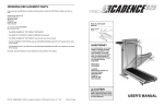
1
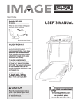
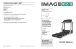
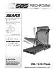
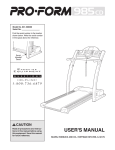
Patent Pending
Model No. 831.285780
Serial No.
Write the serial number in the space
above for future reference.
Serial
Number
Decal
CAUTION
Read all precautions and instructions in this manual before using
this equipment. Keep this
manual for future reference.
USER'S MANUAL
SEARS, ROEBUCK AND CO., HOFFMAN ESTATES, IL 60179
TABLE OF CONTENTS
IMPORTANT PRECAUTIONS . . . . . . . . . . . . . . . . . . . . . . . . . . . . . . . . . . . . . . . . . . . . . . . . . . . . . . . . . . . . . . . .2
BEFORE YOU BEGIN . . . . . . . . . . . . . . . . . . . . . . . . . . . . . . . . . . . . . . . . . . . . . . . . . . . . . . . . . . . . . . . . . . . . . . .3
ASSEMBLY . . . . . . . . . . . . . . . . . . . . . . . . . . . . . . . . . . . . . . . . . . . . . . . . . . . . . . . . . . . . . . . . . . . . . . . . . . . . . . .4
HOW TO USE THE IMAGE¨ 7.0 STEPPER . . . . . . . . . . . . . . . . . . . . . . . . . . . . . . . . . . . . . . . . . . . . . . . . . . . . . .6
TROUBLE-SHOOTING AND MAINTENANCE . . . . . . . . . . . . . . . . . . . . . . . . . . . . . . . . . . . . . . . . . . . . . . . . . . . .8
CONDITIONING GUIDELINES . . . . . . . . . . . . . . . . . . . . . . . . . . . . . . . . . . . . . . . . . . . . . . . . . . . . . . . . . . . . . . . .9
PART LIST . . . . . . . . . . . . . . . . . . . . . . . . . . . . . . . . . . . . . . . . . . . . . . . . . . . . . . . . . . . . . . . . . . . . . . . . . . . . . .10
EXPLODED DRAWING . . . . . . . . . . . . . . . . . . . . . . . . . . . . . . . . . . . . . . . . . . . . . . . . . . . . . . . . . . . . . . . . . . . .11
ORDERING REPLACEMENT PARTS . . . . . . . . . . . . . . . . . . . . . . . . . . . . . . . . . . . . . . . . . . . . . . . . . .Back Cover
FULL 90 DAY WARRANTY . . . . . . . . . . . . . . . . . . . . . . . . . . . . . . . . . . . . . . . . . . . . . . . . . . . . . . . . . .Back Cover
IMPORTANT PRECAUTIONS
WARNING: To reduce the risk of serious injury, read the following important precautions before
using the stepper.
1. Read all instructions in this manual before
using the stepper.
6. The stepper should not be used by persons
weighing more than 250 pounds.
2. It is the responsibility of the owner to ensure
that all users of the stepper are adequately
informed of all precautions.
7. Wear appropriate clothing when using the
stepper. Do not wear loose clothing that
could become caught on the stepper. Always
wear athletic shoes for foot protection.
3. Place the stepper on a level surface. Place a
mat under the stepper to protect the floor or
carpet. Keep the stepper indoors, away from
moisture and dust.
8. If you feel pain or dizziness at any time while
exercising, stop immediately and begin
cooling down.
4. Inspect and tighten all parts of the stepper
regularly. Replace any worn parts
immediately.
9. The stepper is intended for in-home use
only. Do not use the stepper in any
commercial, rental, or institutional setting.
5. Keep children under 12 and pets away from
the stepper at all times.
10. Use the stepper only as described in this
manual.
WARNING: Before beginning this or any exercise program, consult your physician. This is
especially important for persons over the age of 35 or persons with pre-existing health problems.
Read all instructions before using. SEARS assumes no responsibility for personal injury or
property damage sustained by or through the use of this product.
2
BEFORE YOU BEGIN
Thank you for selecting the new IMAGE¨ 7.0 stepper.
Stepping is one of the most effective exercises known
for increasing cardiovascular fitness, building
endurance, and toning the entire body. The IMAGE¨
7.0 stepper blends advanced engineering with
innovative styling to let you enjoy this invigorating
exercise in the comfort and privacy of your own home.
Feel better, look better, and be healthier in just a few
minutes a day.
For your benefit, read this manual carefully before
using the IMAGE¨ 7.0 stepper. If you have questions
after reading the manual, call our toll-free HELPLINE at
1-800-736-6879, Monday through Saturday, 7 a.m.
until 7 p.m. Central Time (excluding holidays). To help
us assist you, please note the product model number
and serial number before calling. The model number is
831.285780. The serial number can be found on a
decal attached to the stepper (see the front cover of this
manual for the location).
Before reading further, please review the drawing
below and familiarize yourself with the parts that are
labeled.
Remote Control Holder
Console
Water Bottle Holder
(Water Bottle is
not included)
Handlebars
Side Shield
Pedals
FRONT
Wheels
Stabilizer
RIGHT SIDE
BACK
3
ASSEMBLY
Assembly requires two people. Place all parts of the stepper in a cleared area and remove the packing materials.
Do not dispose of the packing materials until assembly is completed. Read each step carefully before beginning.
THE FOLLOWING TOOLS ARE REQUIRED FOR ASSEMBLY: The included allen wrench
screwdriver
, and a rubber mallet
.
1. Feed the end of the console wire harness down through the
Upright (2). Attach the Console (50) to the Upright with four #8
x 1/2Ó Screws (25). Be careful to avoid pinching the
console wire harness.
, a phillips
1
50
2
25
Console
Wire Harness
2. Remove the five indicated #8 x 1/2Ó Screws (25) from the
Right Side Shield (55). Remove the five corresponding #8 x
1/2Ó Screws from the Left Side Shield (62). Do not remove
the Side Shields.
2
62
55
25
25
3. While another person holds the Upright (2), connect the
console wire harness to the Lower Wire Harness (32). Refer to
the inset drawing. If the Wire Harnesses do not fit together
easily, turn themÑdo not force them together.
3
2
20
49
20
Tip the Side Shields (55, 62) forward. If the three M10x 25mm
Button Screws (49) and M10 Lock Washers (20) are in the
Frame (1), remove them. Feed the Wire Harness (32) into the
Frame, and slide the Upright (2) onto the Frame. Loosely
thread the three M10 x 25mm Button Screws with M10 Lock
Washers into the Upright and the Frame. After you have
threaded all three Button Screws into the Upright and the
Frame, firmly tighten them.
4
Tip the Side Shields (55, 62) back and reattach them with the
ten #8 x 1/2Ó Screws (25) removed in step 2. Install the bottom
Screws first.
Console
Wire Harness
32
1
49
55, 62
4. Slide the Right Handlebar (10) onto the right side of the
Upright (2). To keep the Handlebar from binding, slide both
ends of the Handlebar on at the same time.
4
25
11
2
While another person pulls back the upper end of the Foam
Handgrip (57), loosely thread two #8 x 1/2Ó Screws (25) into
the Right Handlebar and the Upright. If necessary, move the
Right Handlebar slightly to align the holes in the Right
Handlebar with the holes in the Upright. Next, pull back the
lower end of the Foam Handgrip (57) and loosely thread two
more #8 x 1/2Ó Screws (25) into the Right Handlebar and the
Upright. Tighten all four #8 x 1/2Ó Screws (25).
57
10
25
Attach the Left Handlebar (11) to the Upright (2) in the same
manner.
5. If there are rubber bands on the ends of the 5/8Ó x 15Ó Rod
(43), remove them. Slide a Wheel (44) onto one end of the
Rod. Attach the Wheel with an M6 x 20mm Button Screw (45)
and a 3/8Ó Flat Washer (46).
5
30
Attach a Wheel (44) to the other end of the 5/8Ó x 15Ó Rod (43)
in the same manner.
Plug the Power Cord (30) into the jack on the front of the
stepper.
43
44
46
45
6. Make sure that all parts of the stepper are properly tightened. To protect the floor or carpet from damage,
place a mat under the stepper.
5
HOW TO USE THE IMAGE¨ 7.0 STEPPER
The stepper console offers a variety of features to help
you get the most from your exercise. When the
console is in the manual mode, the stepping speed
can be changed with a touch of a button. As you
exercise, four LED displays will provide continuous
exercise feedback. The console also offers six workout
programs. Each workout program is designed to
change the stepping speed automatically as it guides
you through an effective workout.
DIAGRAM OF THE CONSOLE
1. Program ProfilesÑThese profiles show how the
stepping speed will change during the six workout
programs. During program 5 (Weight Loss 1), for
example, the stepping speed will gradually increase
during the first half of the program, and then
gradually decrease during the last half.
2. Mode IndicatorsÑThese indicators show which
mode is selected (the manual mode or one of the
six workout programs).
3. TIME displayÑWhen the manual mode is selected,
this display will show the elapsed time. When a
workout program is selected, this display shows the
time remaining in the program.
number of repetitions you have completed, divided
by 10. If the display shows 24, for example, you
have completed 240 repetitions.
5. REPS/MIN displayÑThis display shows your
current stepping speed, in repetitions per minute.
6. CALORIES displayÑThis display shows the total
number of calories you have burned and the number
of fat calories you have burned. The display will
change from one number to the other every seven
seconds. When the total number of calories is shown,
the TOTAL indicator will light. When the number of fat
calories is shown, the FAT indicator will light. (See
page 9 for an explanation of fat calories.)
7. MODE buttonÑThis button selects the MANUAL
mode and the six workout programs.
8. START/PAUSE buttonÑThis button starts and
pauses workout programs.
9. REPS buttonÑThis button changes the stepping
speed by increasing or decreasing the stepping
resistance (see step 3 on page 7). Note: When the
maximum speed setting is reached, the MAX
indicator will light. When the minimum speed setting
is reached, the MIN indicator will light.
4. REP SETS displayÑThis display shows the total
3
2
4
5
1
6
9
7
Note: If there is a thin sheet of clear plastic on
the face of the console, remove it before using
the console.
6
8
HOW TO EXERCISE ON THE STEPPER
upper arrow, the resistance will decrease and you
will have to increase your stepping speed to
prevent both pedals from sinking to the floor.
Note: When the stepping speed reaches the
fastest setting, the MAX indicator will light; when
the stepping speed reaches the slowest setting,
the MIN indicator will light.
Place the stepper on a level surface and place a mat
under the stepper. (The stepper features precision
hydraulic cylinders. However, there is a possibility of
slight oil leakage due to the nature of hydraulic cylinders.) Plug the power cord into a 120-volt outlet. All
displays and indicators on the console will flash once;
the displays and various indicators will then light and a
tone will sound.
Hold the handlebars and step onto the pedals. Begin
stepping, alternately depressing the right and left
pedals with a smooth, continuous motion. Because the
pedals move independently of each other, you must
maintain a continuous motion or both pedals will sink
to the floor. Change the height of your step or the
stepping speed until you can comfortably maintain a
continuous motion (see step 3 below).
If you press the START/PAUSE button, or if you
stop exercising for five seconds or longer, a tone
will sound, the console will pause, and the TIME
display will begin to flash. To restart the console,
press the START/PAUSE button or simply begin
stepping.
4
Follow your progress with the four displays.
As you exercise,
the four displays
will provide
continuous
feedback (see
paragraphs 3, 4,
5, and 6 on
page 6).
As you step, you can exercise your upper leg muscles
by keeping your feet flat on the pedals. To focus on
your calf muscles, rise on your toes as you step. Stand
erect or lean forward slightly as you exercise, always
keeping your back straight in order to avoid injury.
HOW TO USE THE MANUAL MODE
1
Turn on the power.
If you just plugged in the power cord or stepped
onto the pedals, the power will already be on.
The power can also be turned on by pressing any
button on the console.
2
Turn off the power.
After the stepper pedals are not moved and the
console buttons are not pressed for ten minutes,
the power will turn off automatically.
Select the manual mode.
HOW TO USE THE WORKOUT PROGRAMS
When the power
is first turned on,
Indicator
the manual mode
will automatically
be selected and
the manual mode
indicator will light.
If a different mode is selected, press the MODE
button repeatedly to select the manual mode.
3
5
Begin stepping and adjust the stepping speed.
Begin stepping
and adjust the
stepping speed as
desired with the
REPS button.
Each step must
travel 5 inches or
more vertically. If you press the lower arrow on
the button, the resistance will increase and your
stepping speed will decrease. If you press the
1
Turn on the power.
See step 1 at the left.
2
Select one of the six workout programs.
Press the MODE
button repeatedly
to select the
desired program.
An indicator will
light to show which
program you have
selected. Programs
1, 2, and 3 are
twenty-minute
programs;
programs 4, 5, and
6 are thirty-minute programs.
7
3
Start the program.
Press the START/PAUSE button and begin
stepping. As you exercise, the stepping speed
will periodically change as shown by the profiles
on the left side of the console. Note: If the
stepping speed is too fast or too slow, it can be
adjusted with the REPS button. When the stepping
speed reaches the fastest setting, the MAX indicator will light; when the stepping speed reaches
the slowest setting, the MIN indicator will light.
To pause the program before the program is
completed, press the START/PAUSE button. A
tone will sound, the console will pause, and the
TIME display will begin to flash. (Note: The
program will also automatically pause if the
pedals are not moved for five seconds.) To
restart the program, press the START/PAUSE
button or simply begin stepping.
The program will continue until no time remains in
the TIME display.
4
Follow your progress with the four displays.
During the program, the four displays will provide
continuous feedback (see page 6).
5
Turn off the power.
After the stepper pedals are not moved and the
console buttons are not pressed for ten minutes,
the power will turn off automatically.
THE INFORMATION MODE
The console features an
information mode that
keeps track of total
stepper usage. To select
the information mode,
first unplug the power
cord. Next, press the
START/PAUSE button
while another person
plugs in the power cord.
Continue pressing the
START/PAUSE button. All displays and indicators on
the console will flash once. After a moment, the TIME
display will show the total number of hours that the
stepper has been used. The REPS/MIN display will
show the total number of repetitions completed,
divided by 100. If the display shows 66, for example,
6600 repetitions have been completed. (Note: If the
number exceeds 999, the overflow will be shown in the
CALORIES display.) To exit the information mode,
press the START/PAUSE button again.
TROUBLE-SHOOTING AND MAINTENANCE
Inspect and tighten all parts of the IMAGE¨ 7.0 stepper regularly. The stepper can be cleaned with a soft cloth
and mild, non-abrasive detergent. Keep liquids away from the console.
HOW TO ADJUST THE REED SWITCH
For the console to display correct feedback the pedals must move
at least 5 inches vertically with each step. If the console displays
incorrect feedback, the Reed Switch (61) should be adjusted.
First, refer to assembly step 2 on page 4 and remove the ten
indicated screws from the Side Shields (55, 62). Next, carefully
slide the Side Shields off the stepper.
62
55
61
Hold down the right pedal so that the Magnet (59) is even with the
Reed Switch (61). Refer to the inset drawing. Loosen the
indicated #8 x 1/2Ó Screw (25), slide the Reed Switch to the side
slightly, and retighten the Screw. Make sure that the Magnet will
not hit the Reed Switch when the Pedal is moved. Repeat until
the console displays correct feedback.
Carefully slide the Side Shields (55, 62) back onto the stepper and
reattach them with the ten #8 x 1/2Ó Screws (25). Install the four
bottom screws first.
8
59
61
59
25
CONDITIONING GUIDELINES
The following guidelines will help you to plan your
exercise program. Remember that a proper diet and
adequate rest are essential for successful results.
WARNING: Before beginning this or any
exercise program, consult your physician.
This is especially important for persons over
the age of 35 or persons with pre-existing
health problems.
EXERCISE INTENSITY
Whether your goal is to burn fat or strengthen your
cardiovascular system, the key to achieving the desired
results is to exercise with the proper intensity. The
proper intensity level can be found by using your heart
rate as a guide. For effective exercise, your heart rate
should be maintained at a level between 70% and 85%
of your maximum heart rate as you exercise. This is
known as your training zone. You can find your training
zone in the table below. Training zones are listed
according to age and physical condition.
minutes of exercise, your body uses easily accessible
carbohydrate calories for energy. Only after the first
few minutes of exercise does your body begin to use
stored fat calories for energy. If your goal is to burn fat,
adjust the intensity of your exercise until your heart
rate is near the low end of your training zone as you
exercise. It may also be helpful to use workout program
3, 5, or 6 on the console (see pages 6, 7, and 8).
Aerobic Exercise
If your goal is to strengthen your cardiovascular
system, your exercise must be Òaerobic.Ó Aerobic
exercise is activity that requires large amounts of
oxygen for prolonged periods of time. This increases
the demand on the heart to pump blood to the
muscles, and on the lungs to oxygenate the blood. For
aerobic exercise, adjust the intensity of your exercise
until your heart rate is near the middle of your training
zone. It may also be helpful to use workout program 1,
2, or 4 on the console (see pages 6, 7, and 8).
HOW TO MEASURE YOUR HEART RATE
To measure your
heart rate, stop
exercising and
place two fingers
on your wrist as
shown. Take a sixsecond heartbeat
count, and multiply
the result by ten to
find your heart
rate. (A six-second
count is used because your heart rate drops quickly
when you stop exercising.) If your heart rate is too
high, decrease the intensity of your exercise. If your
heart rate is too low, increase the intensity of your
exercise.
AGE
UNCONDITIONED
TRAINING ZONE
(BEATS/MIN)
CONDITIONED
TRAINING ZONE
(BEATS/MIN)
20
138-167
133-162
25
136-166
132-160
30
135-164
130-158
35
134-162
129-156
40
132-161
127-155
45
131-159
125-153
50
129-156
124-150
55
127-155
122-149
60
126-153
121-147
WORKOUT GUIDELINES
65
125-151
119-145
70
123-150
118-144
Each workout should include three important parts:
(1) a warm-up, (2) training zone exercise, and (3) a
cool-down.
75
122-147
117-142
80
120-146
115-140
85
118-144
114-139
Burning Fat
To burn fat, you must exercise at a low intensity level
for a sustained period of time. During the first few
Warming up
Warming up prepares the body for exercise by
increasing circulation, delivering more oxygen to the
muscles, and raising the body temperature. Begin
each workout with 5 to 10 minutes of stretching and
light exercise to warm up.
9
Training Zone Exercise
EXERCISE FREQUENCY
After warming up, increase the intensity of your
exercise until your heart rate is in your training zone for
20 to 30 minutes. Breathe regularly and deeply as you
exerciseÑnever hold your breath.
To maintain or improve your condition, plan three
workouts each week, with at least one day of rest
between workouts. After a few months of regular
exercise, you may complete up to five workouts each
week, if desired.
Cooling Down
Finish each workout with 5 to 10 minutes of stretching.
Stretching after exercise develops flexibility and helps
prevent post-exercise problems. A proper cool-down
should leave you feeling relaxed and comfortably tired.
Remember, the key to success is to make exercise a
regular and enjoyable part of your everyday life.
PART LISTÑModel No. 831.285780
10
Key
No.
Part
No.
Qty.
1
2
3
4
5
6
7
8
9
10
11
12
13
14
15
16
17
18
19
20
21
22
23
24
25
26
27
28
29
30
31
32
NSP
138777
138756
138757
138758
138760
138759
138761
138771
138775
138776
137821
138773
120271
127551
138768
012142
120274
120273
121519
013463
138767
133807
138763
013576
138764
138765
137579
138780
109954
138871
119394
1
1
1
1
1
1
1
1
2
1
1
2
2
2
4
4
4
1
1
3
4
8
1
1
29
4
4
2
2
1
2
1
Description
Frame
Upright
Right Pedal Bracket
Left Pedal Bracket
Right Upper Pedal Arm
Left Upper Pedal Arm
Right Lower Pedal Arm
Left Lower Pedal Arm
3 3/8Ó Plastic Spacer
Right Handlebar
Left Handlebar
Shock w/Gear and Bushing
Limit Pin
Shock Clamp
M6 X 20mm Bolt
M6 Flat Washer
M6 Locknut
Motor Assembly
Motor Gear
M10 Lock Washer
#10 x 1Ó Motor Screw
Cork Washer
Motor Shaft Bushing
Limit Switch Bracket
#8 x 1/2Ó Screw
#3 x 3/4Ó Limit Switch Screw
#3 Limit Switch Washer
Cable
Pulley w/Bearing
Power Cord w/Transformer
Side Shield Bracket
Lower Wire Harness
R0697A
Key
No.
Part
No.
Qty.
33
34
35
36
37
38
39
40
41
42
43
44
45
46
47
48
49
50
51
52
53
54
55
56
57
58
59
60
61
62
63
#
104622
125755
133811
013282
110576
120414
101768
103903
109470
115425
138769
138772
013033
138770
138872
138766
121518
138870
130287
133760
138754
012077
138778
013200
138774
113494
138762
138869
128775
138779
138755
138572
4
2
2
8
16
2
2
12
4
1
1
2
2
2
2
4
3
1
2
4
4
4
1
2
2
4
1
1
1
1
4
1
Description
#8 x 3/8Ó Screw
Foam Stop Cover
Pedal Cover
#8 x 1/2Ó Pedal Screw
Bronze Pivot Bushing
Frame Endcap
3/8Ó Axle Cap
1/2Ó Axle Cap
1/2Ó x 3 1/2Ó Rod
3/8Ó x 6 3/4Ó Rod
5/8Ó x 15Ó Rod
Wheel
M6 x 20mm Button Screw
3/8Ó Flat Washer
Rubber Bumper
#3 Limit Switch Nut
M10 x 25mm Button Screw
Console
M10 x 72mm Bolt
M10 x 38mm Bolt
Shock Bracket
M10 Locknut
Right Side Shield
Limit Switch
Foam Handgrip
Weld Spacer
Magnet w/Mount
Wiring Clip
Reed Switch
Left Side Shield
1/4Ó Spacer
UserÕs Manual
Note: "#" indicates a non-illustrated part. Specifications are subject to change without notice. See the back cover
of this manual for information about ordering replacement parts.
R0697A
EXPLODED DRAWINGÑModel No. 831.285780
10
57
25
25
38
49
20
35
3
57
36
2
11
20
20
25
49
35
49
1
25
36
38
50
32
62
33
37
34
15 60
28
47
40
59
51
5
29
21
19
16
22
42
12
18
22
58
28
41
37
21
16
22
48
27
56
26
54
63
12
32
33
13
39
52
53
22
7
43
37
41
40
48
27
25
24
44
54
53
23
26
63
40
17
28
14
9
37
37
40
30
61
46 45
25
31
55
25
25
11
The model number and serial number of your IMAGE¨ 7.0 stepper
are listed on a decal attached to the frame. See the front cover of
this manual to find the location of the decal.
Model No. 831.285780
QUESTIONS?
If you find that:
¥ you need help assembling or
operating the stepper
¥ a part is missing
¥ or you need to schedule repair
service
call our toll-free HELPLINE
All replacement parts are available for immediate purchase or
special order when you visit your nearest SEARS Service Center.
To request service or to order parts by telephone, call the toll-free
numbers listed at the left.
When requesting help or service, or ordering parts, please be
prepared to provide the following information:
¥ The NAME OF THE PRODUCT (IMAGE¨ 7.0 stepper)
¥ The MODEL NUMBER OF THE PRODUCT (831.285780)
1-800-736-6879
¥ The PART NUMBER OF THE PART (see page 10)
MondayÐSaturday, 7 amÐ7 pm
Central Time (excluding holidays)
¥ The DESCRIPTION OF THE PART (see page 10)
REPLACEMENT
PARTS
If parts become worn and need to
be replaced, call the following
toll-free number
1-800-FON-PART
(1-800-366-7278)
FULL 90 DAY WARRANTY
For 90 days from the date of purchase, if failure occurs due to defect in material or workmanship in this
STEPPER EXERCISER, contact the nearest SEARS Service Center throughout the United States and
SEARS will repair or replace the STEPPER EXERCISER, free of charge.
This warranty does not apply when the STEPPER EXERCISER is used commercially or for rental
purposes.
This warranty gives you specific legal rights, and you may also have other rights which vary from state
to state.
SEARS, ROEBUCK AND CO., DEPT. 817WA, HOFFMAN ESTATES, IL 60179
Part No. 138572 G01482AC R0697A
Printed in USA © 1997 Sears, Roebuck and Co.