1
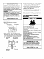
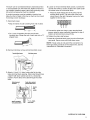
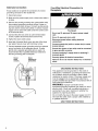
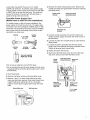
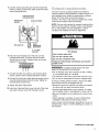
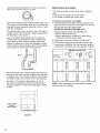
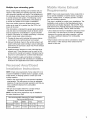
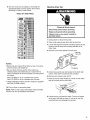
TABLE OF CONTENTS
Dryer Safety ............................................................
2
Installation Instructions .........................................
3
Electrical requirements ........................................
3
Exhaust requirements ..........................................
9
Recessed area/closet installation ...................... 11
COIN-OPERATED
COMMERCIAL
ELECTRICDRYER
Mobile home exhaust requirements ................... 11
Installing the dryer .............................................
Operating
the dryer ..............................................
Troubleshooting
....................................................
Service and Assistance .......................................
12
16
17
20
For Sears warranty information or to contact a Sears Service
Center, call 1-800-4-MY HOME S_(1-800-469-4663).
IMPORTANT:
operating
OWNER'S MANUAL
and
INSTALLATION
INSTRUCTIONS
Read and follow all safety, installation,
instructions before first use of this product.
and
If you need SERVICE or PARTS for your
Kenmore coin-operated
dryer:
When requesting service, be ready to give the model
number, serial number (located on a tag in the door well
behind the door) and date of purchase. Record below.
Model No
Serial No.
SEARS,ROEBUCK
AND CO.
HoffmanEstates,IL 60179
Date of Purchase
Record Coin Box
Key Number
www.sears.com
Key number
3397630
PRINTED JNTHE U S A
4/99
is on key and/or coin box.
DRYER SAFETY
YOUR
SAFETY
AND
THE
SAFETY
OF OTHERS
IS VERY
IMPORTANT.
We have provided many important safety messages in this manual and on your appliance. Always read and obey
all safety messages.
This is the safety alert symbol.
This symbol alerts you to hazards that can kill or hurt you and others.
All safety messages will be preceded by the safety alert symbol and the word "DANGER" or
"WARNING". These words mean:
You wil__l
be killed or seriously injured if you don't
follow instructions.
You cart be killed or seriously injured
follow instructions.
if you don't
All safety messages will identify the hazard, tell you how to reduce the chance of injury, and tell you what can
happen if the instructions are not followed.
IMPORTANT
SAFETY
WARNING:
To reduce the risk of fire, electric shock,
follow basic precautions, including the following:
• Read all instructions
the dryer.
before using
• Do not place items exposed to cooking
oils in your dryer. Items contaminated with
cooking oils may contribute to a chemical
reaction that could cause a load to catch
fire.
• Do not dry articles that have been
previously cleaned in, washed in, soaked
in, or spotted with gasoline, dry-cleaning
solvents, other flammable, or explosive
substances as they give off vapors that
could ignite or explode.
• Do not allow children to play on or in
the dryer. Close supervision of children
is necessary when the dryer is used
near children.
INSTRUCTIONS
or injury to persons
• Do not repair or replace any part of the
dryer or attempt any servicing unless
specifically recommended
in this Use and
Care Guide or in published user-repair
instructions that you understand and have
the skills to carry out.
• Do not use fabric softeners or products to
eliminate static unless recommended
by
the manufacturer
of the fabric softener
or product.
• Do not use heat to dry articles containing
foam rubber or similarly textured rubberlike materials.
• Clean lint screen before or after each load.
• Keep area around the exhaust opening
and adjacent surrounding areas free from
the accumulation
of lint, dust, and dirt.
• Before the dryer is removed from service
or discarded, remove the door to the drying compartment.
• The interior of the dryer and exhaust vent
should be cleaned periodically by
qualified service personnel.
• Do not reach into the dryer if the drum
is moving.
• See Installation
requirements.
• Do not install or store the dryer where
it will be exposed to the weather.
• Do not tamper with controls.
SAVE THESE
2
when using the dryer,
INSTRUCTIONS
Instructions
for grounding
INSTALLATION
INSTRUCTIONS
Three-Wire
Receptacle
Electrical
Connection
to
Read the "Dryer Safety" section of this Owner's Manual
and completely read these Installation Instructions before
beginning installation.
IMPORTANT: Observe all governing codes and
ordinances.
• The dryer must not be installed where it can be
exposed to water and/or weather.
• Check code requirements. Some codes limit or do not
permit installation of clothes dryers in garages, closets,
mobile homes, or sleeping quarters. Contact your local
building inspector.
Fire Hazard
Use a new UL approved 30 ampere power supply
cord.
Use a UL approved strain relief.
Tools needed for installation:
Disconnect power before making electrical
connections.
Adjustable wrench or Pliers
N-inch nut driver
Connect neutral wire (white or center wire) to center
terminal (silver).
Wire stripper
Duct tape
Phillips screwdriver
Flat-head screwdriver
Level
Ground wire (green or bare wire) must be connected
to green ground connector.
Connect remaining 2 supply wires to remaining 2
terminals (gold).
Securely tighten all electrical connections.
Failure to do so can result in death, fire, or
electrical shock.
A three-wire or four-wire, single phase 120!240-volt,
60-Hz., AC-only, electrical supply is required on a
separate 30-ampere circuit, fused on both sides of the
line. A time-delay fuse or circuit breaker is recommended.
This dryer is manufactured with the 3-wire, flame-grounding conductor connected to the NEUTRAL (center) of the
wiring harness of the terminal block. Do not have a fuse
in the neutral or grounding circuit.
Use a 4-conductor cord when the dryer is installed in a
mobile home or an area where local codes do not permit
grounding through the neutral.
Local codes may permit the use of a U.L.-listed,
120/240-volt minimum, 30-ampere, dryer power supply
cord kit (pigtail). Power supply cord should be type SRD
or SRDT and be at least four feet long. The wires that
connect to the dryer must end with ring terminals or
spade terminals with upturned ends.
Spade terminals .........
with upturnedends
1
J
This blade connected
NEUTRAL
_ to this conductor
Ring
terminals
/f,+ ............................
¾, U.L.-listed, +
strainrelief
%
NEUTRAL
(whiteorcenter)
• The power supply cord must have three, No.-10 copper
wires to match a three-wire receptacle of NEMA Type
10-30R.
Three-wire
receptacle (NEMA
Type10-30R)
• Do not use an extension cord with this dryer.
• Do not connect plug end of power supply cord into a
live receptacle before connecting power supply cord to
dryer terminal block.
3
GROUNDING
INSTRUCTIONS
This appliance must be grounded. In the event of
malfunction or breakdown, grounding will reduce the
risk of electric shock by providing a path of least
resistance for electric current. The power supply cord
must be plugged into an appropriate outlet that is
properly installed and grounded in accordance with all
local codes and ordinances.
WARNING:
Improper connection of the equipmentgrounding conductor can result in a risk of electric
shock. Check with a qualified electrician or serviceman
if you are in doubt as to whether the appliance is
properly grounded. Do not modify the plug on the
power supply cord. If it will not fit the outlet, have a
proper outlet installed.
4. Loosen or remove terminal block screws. Connect the
neutral wire (white or center) of power supply cord
under the center screw of the terminal block.
5. Connect the other two wires to outer terminal block
screws. Tighten all terminal block screws firmly.
6. Tighten the strain relief screws.
7. Insert tab of terminal block cover into slot of the dryer
rear panel. Secure cover with hold-down screw.
NOTE: If local codes do not permit the connection of a
frame-grounding conductor to the neutral wire, see the instructions for "Alternate Connection" later in this section.
Three-Wire
Electrical
(Direct Wire)
Connection
SAVETHESEINSTRUCTIONS
1. Disconnect power.
2. Remove hold-down screw and terminal
block cover.
Terminal
block
cover
Hold-down
screw
Fire Hazard
Use 10 gauge solid copper wire.
Use a UL approved strain relief.
Disconnect power before making electrical
connections.
Connect neutral wire (white or center wire) to center
terminal (silver).
3. Attach a ¾-inch, U.L.-listed, strain relief to the hole
below terminal block opening. Strain relief should have
a tight fit with dryer cabinet and be in a horizontal position. Put the power supply cord through the strain relief.
Externalground
connector
Center silver-colored
terminal block screw
Neutral
(white)
Ground wire (green or bare wire) must be connected
to green ground connector.
Connect remaining 2 supply wires to remaining
2 terminals (gold).
Securely tighten all electrical connections.
Failure to follow these instructions can result in
death, fire, or electrical shock.
GROUNDING
This appliance must be connected to a grounded
metal, permanent wiring system; or an equipmentgrounding conductor must be run with the circuit
conductors and connected to the equipment-grounding
terminal or lead on the appliance.
SAVE THESE
Neutral grounding wire
(green/_/ellow)
4
_", U.L.-listed,
strain relief
INSTRUCTIONS
INSTRUCTIONS
Thedryercanbeconnected
directlyto fuseddisconnect
orcircuitbreakerboxwiththree-wire,
flexiblearmoredor
non-metallic
sheathed
coppercable(withgrounding
wire).
All current-carrying
wiresmustbeinsulated.
A conduitconnectormustbeinstalledatjunctionbox.
Allowfourfeetof slackinthelinesodryercanbemoved
ifservicingisevernecessary.
4. Loosen or remove terminal block screws. Connect the
neutral wire (white or center) of direct wire cable under
the center screw of the terminal block.
• Place the hook-shaped end of the wire over the
terminal block screw. The open side of the hook
should face to the right. Squeeze hook end of wire
together to form a loop.
1.Disconnect
power.
• Strip 3½ inches of outer covering from end of cable.
•
_/
• Cut 1 inch of insulation from the end of each
insulated wire. Shape the end of each wire into a "U"
shaped hook.
5. Connect the other two wires to outer terminal block
screws using the same method(s) described in step 4.
Tighten all terminal block screws firmly.
6. Tighten the strain relief screws.
7. Insert tab of terminal block cover into slot of the dryer
rear panel. Secure cover with hold-down screw.
NOTE: If local codes do not permit the connection of a
frame-grounding conductor to the neutral wire, see the
instructions for "Alternate Connection."
2. Remove
hold-down
screw and terminal
Terminalblockcover
block cover.
Hold-down
screw
3. Attach a ¾-inch, U.L.-listed, strain relief to the hole
below terminal block opening. Strain relief should have
a tight fit with dryer cabinet and be in a horizontal
position. Put the direct wire cable through the strain
relief.
Externalground
connector
Center silver-colored
terminal block screw
Neutral
(white)
Neutral grounding
wire (green/yellow)
¾", U.L-listed,
strain relief
continued on next page
5
Alternate
Connection:
Four-Wire
If local codes do not permit the connection of a framegrounding conductor to the neutral wire:
Electrical
Connection
to
Receptacle
1. Disconnect power.
2. Make sure the power supply cord or direct wire cable is
in place.
3. Remove the neutral grounding wire (green/yellow wire)
from external grounding connector screw. Loosen or
remove terminal block screws. Connect neutral grounding wire and the neutral wire (white or center) of power
supply cord or direct wire cable under the center screw
of the terminal block.
4. Connect the other two wires to outer terminal block
screws. Tighten all terminal block screws firmly.
5. Tighten the strain relief screws.
6. Insert tab of terminal block cover into slot of the dryer
rear panel. Secure cover with hold-down screw.
7. Connect separate copper grounding wire from external
ground connector to an adequate ground. If codes
permit and a separate grounding wire is used, it is
recommended that a qualified electrician determine
that the grounding path is adequate.
External
ground
connector
Neutral
groundingwire
(green/yellow)
Fire Hazard
Use a new UL approved 30 ampere power supply
cord.
Use a UL approved strain relief.
Disconnect power before making electrical
connections.
Connect neutral wire (white or center wire) to center
terminal (silver).
Ground wire (green or bare wire) must be connected
to green ground connector.
Connect remaining 2 supply wires to remaining 2
terminals (gold).
Securely tighten all electrical connections.
Failure to do so can result in death, fire, or electrical
shock.
GROUNDING
INSTRUCTIONS
This appliance must be grounded. In the event of
malfunction or breakdown, grounding will reduce the
risk of electric shock by providing a path of least
resistance for electric current. The power supply cord
must be plugged into an appropriate outlet that is
properly installed and grounded in accordance with all
local codes and ordinances.
WARNING:
Improper connection of the
equipment-grounding conductor can result in a risk of
electric shock. Check with a qualified electrician or
serviceman if your are in doubt as to whether the
appliance is properly grounded.
Groundingpath
determined by a
qualified electrician
Do not modify the plug on the power supply cord. If it
will not fit the outlet, have a proper outlet installed by
a qualified electrician.
SAVE THESE INSTRUCTIONS
6
Localcodesmaypermitthe useofa U.L.-listed,
120/240-volt
minimum,30ampere,dryerpowersupply
cordkit(pigtail).PowersupplycordshouldbetypeSRD
or SRDTandbeat leastfourfeetlong.Thewiresthat
connecttothe dryermustendwithringterminalsor
spadeterminalswithturnedends.
4. Remove the center terminal block screw. Remove the
neutral grounding wire (green/yellow wire) from external
grounding screw.
External ground
connector,
Center silver-colored
terminal block screw
Four-Wire Power Supply Cord
(Mobile home or other four-wire installations)
For mobile homes or other four-wire installations, the
power supply cord must have four, No.-10 copper wires
and match a four-wire receptacle of N EMA Type 14-30R.
The fourth wire (grounding conductor) must be identified
with a green cover or bare copper wire and the neutral
conductor by a white cover.
NEUTRAL
NEUTRAL
(whi_)
_", U.L.-li_ed,
strain relief
/
Green/yeNow wire
of harooss
5. Connect neutral grounding wire and the neutral wire
(white) of power supply cord under the center screw of
terminal block.
6. Connect the other two insulated wires to outer terminal
block screws.
nr_nnain.
prong
,s'
wim(green)
•
terminals
7. Connect the green, grounding wire from the power
supply cord to the external grounding conductor screw.
Tighten all terminal block screws firmly.
8. Tighten the strain relief screws.
Four-wErereceptacle
(NEMA Type14-30R)
9. Insert tab of terminal block cover into slot of the dryer
rear panel. Secure cover with hold-down screw.
Center silver-colored
External
ground
terminal
block
screw Neutral wire
(white)
connector
• Do not use an extension cord with this dryer.
• Do not connect plug end of power supply cord into a live
receptacle before connecting power supply cord to dryer
terminal block.
1. Disconnect power.
2. Remove hold-down screw and terminal block cover.
3. Attach a ¾-inch, U.L.-listed, strain relief to the hole
below terminal block opening. Strain relief should have
a tight fit with dryer cabinet and be in a horizontal
position. Put the power supply cord through the strain
relief.
Terminal block cover
Green
wire/;'_
ofpower
supply
cordorbare
copper
wire
I
_._
%_ Neutral grounding wire
(green_ellow)
Hold-down
screw
_", U.L-listed,
strain relief
7
Four-Wire
Electrical
Direct Wire)
Connection
Fire Hazard
1. Disconnect power.
• Strip 5 inches of outer covering from end of cable.
Leave bare grounding wire at 5 inches.
• Cut 1 inch from 3 remaining insulated wires. Strip
insulation back 1 inch. Shape the end of each wire
into a "U" shaped hook.
Use 10 gauge solid copper wire.
Use a UL approved strain relief.
Disconnect power before making electrical
connections.
Connect neutral wire (white or center wire) to center
terminal (silver).
Ground wire (green or bare wire) must be connected
to green ground connector.
Connect remaining 2 supply wires to remaining 2
terminals (gold).
2. Remove hold-down screw and terminal block cover.
Terminal
block
cover
Hold-down
screw
Securely tighten all electrical connections.
Failure to follow these instructions can result in
death, fire, or electrical shock.
GROUNDING INSTRUCTIONS
This appliance must be connected to a grounded
metal, permanent wiring system; or an equipmentgrounding conductor must be run with the circuit
conductors and connected to the equipmentgrounding terminal or lead on the appliance.
SAVE THESE INSTRUCTIONS
The dryer can be connected directly to fused disconnect
or circuit breaker box with four-wire, flexible armored or
non-metallic sheathed copper cable (with grounding wire).
All current-carrying wires must be insulated. The grounding wire may be bare.
3. Attach a H-inch, U.L.-listed, strain relief to the hole
below terminal block opening. Strain relief should have
a tight fit with dryer cabinet and be in a
horizontal position. Put the direct wire cable through
the strain relief.
4. Remove the center terminal block screw. Remove the
neutral grounding wire (green/yellow wire) from
external grounding screw.
External ground
A conduit connector must be installed at junction box.
Allow four feet of slack in the line so dryer can be moved
if servicing is ever necessary.
Green/yellow wire
of harness
8
Center silver-colored
terminal block screw
5.Connectneutralgrounding
wireandtheneutralwire
(whiteor center)of directwirecableunderthecenter
screwofterminalblock.
Center silver-colored
terminal block screw
Externalground
connector
II
Neutral wire (white)
/
dL II
The dryer must be properly installed and vented to
achieve maximum drying efficiency. Install the dryer in a
well-ventilated room where the temperature is always
above 45°R Also make sure that the dryer is
leveled. If the dryer is not properly installed and vented,
it will not be covered under the warranty.
NOTE: Service calls caused by improper venting will be
paid for by the customer, whether it was a paid installation or self-installed. For paid installation, call the
company that installed the vent for adjustment.
,arece,,er
w re I III". gr0ced .,w re
_
(green/yellow)
¾", U.L-listed,
strain relief
Fire Hazard
Use a heavy metal vent.
6. Place the hook-shaped end of the wire over the
terminal block screw. The open side of the hook
should face to the right. Squeeze hook end of wire
together to form a loop.
Do not use a plastic vent.
Do not use a metal foil vent.
Failure to follow these instructions can result in
death or fire.
WARNING:
To reduce the risk of fire, this dryer
MUST BE EXHAUSTED OUTDOORS.
7. Connect the other two wires to outer terminal block
screws. Use the same method described in Step 6.
* Do not exhaust dryer into a chimney, a wall, a ceiling,
or a concealed space of a building.
* The diameter of the heavy metal vent must be 4 inch.
8. Connect the direct wire cable (bare) grounding wire to
the external-grounding conductor screw. Tighten all
terminal block screws firmly.
* Do not use an exhausted hood with a magnetic latch.
9. Tighten the strain relief screws.
* Disconnect vent from the dryer and clean one section
at a time until you reach the exhaust hood.
10. Insert tab of terminal block cover into slot of the dryer
rear panel. Secure cover with hold-down screw.
If using an existing exhaust system, remove lint. Make
sure exhaust hood is not plugged with lint.
* Use the hose attachment on your vacuum, or a pole
with a feather duster or rag attached, to clean out lint.
* Be sure the flapper on the outside end of vent moves
freely.
* When cleaning is complete, be sure to follow these
Installation Instructions for final product check.
Clean exhaust vent periodically, depending on use, but
at least every 2 years, or when installing your dryer in a
new location.
continued on next page
9
Useducttapeto sealalljoints.Donotusescrewsto
securevent.Lintmaycatchonscrews.
Determining
vent length
The maximum length of the exhaust system depends
upon:
• The type of vent (heavy or flexible metal).
• The number of elbows (90 ° turns) used.
Use4-inchdiameterheavymetalorflexiblemetalvent.
Donotkinkor crushflexiblemetalvent.It mustbefully
extendedto allowadequateexhaustairto flow.Check
ventafterinstallation.
Theexhaustventcanberoutedup,down,left,right,or
straightoutthebackofthe dryer.Spacerequirements
arelistedlaterinthissection.
Usethestraightest
pathpossiblewhenroutingthe
exhaustvent.Usethefewestnumberofelbowsand
turns.Allowas muchroomas possiblewhenusing
elbowsor makingturns.Bendventgraduallytoavoid
kinking.Removeexcessflexibleventtoavoidsagging
andkinkingthatmayresultin reducedairflow.
To determine maximum vent length:
1. See the Exhaust Hood Type chart that matches your
type hood for the maximum vent lengths you can use.
Do not use vent runs longer than
specified in exhaust vent length chart,
Exhaust systems longer than specified will:
• Shorten the life of the dryer.
• Reduce performance, resulting in longer drying
times and increased energy usage.
2. Determine the number of elbows you will need.
3. In the column listing the type of metal vent you are
using (heavy or flexible), find the maximum length of
metal vent on the same line as the number of elbows.
EXHAUST HOOD TYPE
Numberof
90° Turns
_
"_
_-_
Maximum length of 4-inch diameter heavy metal vent.
Good
0
1
2
3
4
Exhaust airflow
Maximum length of the exhaust system depends upon
the type of vent used, number of elbows, and the type
of exhaust hood. The maximum length for both heavy
and flexible metal vent is shown in the chart following.
See figure 1 for exhaust outlet location (at rear of
the dryer) and dimensions. Minimum side and rear
clearances appear on model and rating plate on back
of dryer.
,
Exhaust Outlet
4'¸ DFa
Location
(Rear of Dryer)
FIGURE 1
10
64 ft.
54 ft.
44 ft.
35 ft.
27 ft.
64 ft.
54 ft.
44 ft.
35 ft.
27 ft.
58 ft.
48 ft.
38 ft.
29 ft.
21 ft.
Maximum length of 4-inch diameter flexible metal vent.
0
1
2
3
4
36 ft.
31 ft.
27ft.
25ft.
23ft.
36 ft.
31 ft.
27ft.
25ft.
23ft.
28 ft.
23 ft.
19ft.
17ft.
15ft.
NOTE: Check periodically to ensure that the outside
exhaust hood is not blocked.
Multiple
dryer exhausting
guide
Many multiple-family dwellings are furnished with provisions in the building for washing and drying laundry
with automatic washers and dryers. The exhausting of
the individual clothes dryers can be accomplished with
a central exhaust vent system. The following is a list
of factors for possible consideration in the design of
a central vent system for this type of installation.
Each room where dryers are located should have
make-up air equal to or greater than the CFM of all
dryers in the room.
This information is intended for general guide purposes
only and does not necessarily include all factors which
may be required for consideration in a given situation.
If specific information on multiple exhausting is required,
contact a local sheet metal contractor.
1. Provide all dryers with individual lint screens before
connecting to any central exhaust vent system.
2. Exhaust individual dryers to the central exhaust vent
system with proper sized venting to assure adequate
performance of each dryer. (Dryer has 4-inch exhaust
vent connection.)
NOTE: Check code requirements. Some codes limit or
do not permit installation of clothes dryers in garages,
closets, mobile homes, or sleeping quarters. Contact
your local building inspector.
This dryer is suitable for mobile home installations. The
installation must conform to the Manufactured Home
Construction and Safety Standard, Title 24 CFR, Part
3280 (formerly the Federal Standard for Mobile Homes
Construction and Safety, Title 24, HUD Part 280).
• Use at least the minimum installation clearance shown
in the chart. This will ensure you have an adequate
clearance for service and proper operation and that
you have a sufficient distance from combustible
construction.
• Dryer exhaust vent must not be connected or secured
with screws or other devices which extend into the
interior of the vent.
3. Install barometric dampers on each individual dryer
exhaust vent. These dampers may be used for balancing out the overall vent system. Dampers may be
secured or built locally from a sheet metal fabricator.
4. Make all electric supply connections to individual
dryers in accordance with manufacturer's installation
instructions and applicable local codes requirements.
NOTE: Check code requirements. Some codes limit or do
not permit installation of clothes dryers in garages, closets,
mobile homes, or sleeping quarters. Contact your local
building inspector.
• Refer to the chart below for recommended installation
requirements. This will ensure you have an adequate
clearance for service and proper operation and that you
have a sufficient distance from combustible
construction.
• Be sure your location allows for a proper exhaust
installation. See "Exhaust requirements."
NOTE: No fuel-burning appliances may be installed in
the same closet as a dryer.
Use recommended clearance for easier installation
Recommended/Minimum
Back
Sides
Top
Recessed
5 in/0 in
1 in/0 in
18 in/18 in
Closet
5 in/4 in
1 in/0 in
18 in/18 in
Front
1 in/1 ir
11
NOTES:
* Do not move dryer by grasping console.
* Rough handling or moving dryer over rough floor can
result in damage to leveling feet.
* Slide dryer onto cardboard or hardboard before
moving across floor.
1. Open dryer and remove any shipping tape that
secures the dryer drum. Remove all parts, packages,
and leveling feet.
Explosion Hazard
Keep flammable materials and vapors, such as
gasoline, away from dryer.
Place dryer at least 18 inches (46 cm) above
the floor for a garage installation.
2. Move dryer close to permanent location.
3. Install leveling legs:
* Take two of the cardboard corners from the carton
and place them on the floor in back of the dryer.
Firmly grasp the body of the dryer and gently lay it
back on the cardboard corners.
Failure to do so can result in death, explosion,
or fire.
* Check leg for diamond marking. This is how far the
leg should go into the hole. Start to screw legs into
holes by hand. A little liquid detergent applied to the
legs will help lubricate them.
* Use a 1-inch wrench to finish turning the legs until
you reach the diamond mark.
Excessive Weight Hazard
Use two or more people to move and
install dryer.
Failure to do so can result in back or
other injury.
Cardboard
I
I
corners
I
I
Diamond
Leveling leg
4,
Level dryer:
• Stand the dryer up and move it close to its final
location, Leave enough room to connect the
exhaust vent.
• Check levelness of dryer by placing a level on top of
the dryer, first side-to-side; then front-to-back.
• If the dryer is not level, prop the dryer up using two
stacked cardboard corner posts.
• Use a wrench to adjust the legs up or down until the
top of the dryer is level.
12
Installing
coin-slide
mechanism
NOTE: If the coin-slide mechanism is installed, skip this
step and proceed to coin-box adjustment.
Remove the service door from the meter case by unlocking the service lock with the key shipped with the dryer.
Starting the dryer without
mechanism
using the coin
1. Close the dryer door.
2. Push the PUSH TO START button firmly.
Carefully insert coin-slide mechanism into opening and
guide into holes. Secure the coin slide with bolt from
inside the meter case.
Electrical Shock Hazard
Disconnect
NOTE: Removing timer from mounting screws may
facilitate inserting the bolt.
Replace the service door. Be sure the lock is located
toward the rear of the case.
Coin box adjustment
The tight fit of the money box is set at the factory.
Customer may loosen fit as desired by loosening the
slotted nuts.
power before servicing.
Replace all panels before operating.
Failure to do so can result in death or
electrical shock.
3. If the dryer does not start, remove the meter-case
service door.
4. Push the ratchet arm towards the rear of the dryer
until it stops, then release.
5. Replace the meter-case service door. Be sure the
lock is located toward the rear of the case.
6. Push the PUSH TO START button firmly.
Arm
Keep a record of all coin-box key numbers. A lost key
can only be replaced if ordered by key number from Sears
Parts. The key number is located both on the key and
behind the end panel of the coin box. If the key number
is not available, the lock must be drilled out to remove
the coin box.
Replace
meter-case
Final installation
access
panel.
connection
1. Connect exhaust vent to exhaust outlet of the dryer.
2. Carefully move dryer into permanent location.
Provide at least the minimum installation clearances
between dryer and rear wall. See the chart. This will
ensure you have an adequate clearance for service
and proper operation and that you have sufficient
distance from combustible construction.
3. Plug in dryer or connect power.
13
Replacing nylon timing cams on
accumulator
mechanism
Changing
Vend Price
Follow all instructions
carefully.
NOTE: Place all screws and other items removed from
coin slide assembly on a cloth so they will not get lost.
Electrical Shock Hazard
Disconnect
power before servicing.
Replace all panels before operating,
Failure to do so can result in death or
electrical shock.
Electrical Shock Hazard
Disconnect
power before servicing.
Replace all panels before operating.
Failure to do so can result in death or
electrical shock.
1. Unplug dryer or disconnect power.
2. Remove meter-case service door:
• Loosen two screws securing timer bracket to meter
case and lift timer assembly out.
3. Remove nylon timing cam:
1. Unplug dryer or disconnect power.
2. Remove slide mechanism from meter case.
• Rotate cam by hand until "V" notch lines up underneath the ratchet tooth.
Timing Cam
Line Up Notch
to Clear Ratchet
Tooth
Hub Down
with Narrow
Blade
3. Remove slide return spring.
• Insert narrow screwdriver under nylon cam close to
the timer shaft. Lift cam gently off shaft. Make sure
that pressure is directed upward and the "V" notch
clears the ratchet tooth.
4. Replace new timing cam:
• Be sure drive lug is in place. Place cam (hub down)
over timer shaft, lining up flat on shaft with fiat of
drive lug hole.
• Rotate cam until "V" notch lines up with ratchet
tooth.
• Press down to seat cam on timer shaft. Make sure
that "V" notch freely clears ratchet tooth.
NUMBER
OF PINS
TIME PER
COIN INSERTED
6 Light Red
4 Light Yellow
3 Light Green
30
45
60 (Installed)
5. Plug in dryer or reconnect
14
power.
4. Place coin(s) in coin slot(s) and push forward all
the way.
5. Remove buffer.
6. Turn coin chute upside down and install or remove
required number of block-out keys. Remove keys to
increase vend, add keys to lower vend.
7. Reassemble buffer.
8. Pull slide back to original position and reassemble
slide return spring.
9. Set new vend price by adding or removing the
appropriate block-out keys and/or dime inserts
according to Table of Vend Prices.
Opening
dryer top
TABLE OF VEND PRICE
VENO
PRICm
COIN
BLOTB
IRa4nSTn
o
IIIIIIII
lo¢u1111111
25¢11DIIIII
35¢DIDIIIII
5o¢IIDDIIII
8o¢ DIDDIIII
75¢IIDDDIII
85¢ DIDDDIII
=I.oo IIDDDDII
=1.1o
=1.25
=1.35
=1.5o
• 1.so
=1.75
ulDDDDII
IDDDDDII
DIDDDDDI
IDDDDDDI
uDDDDDDI
IDDDDDDD
=I.a5 uDDDDDDD
Electrical Shock Hazard
Disconnect
power before servicing.
Replace all panels before operating,
Failure to do so can result in death or
electrical shock.
1. Unplug dryer or disconnect power.
2. Open meter-case access door with top-lock key.
3. Loosen the two timer bracket mounting screws (do not
remove) and lift timer and mounting bracket out of
meter case.
4. Remove nut and tee spacer from the stud.
yjf
Security
Top Lock
=2.oo IDDDDDDD
NOTES:
* Black slots are closed off by block-out key. To remove
block-out keys, pull straight up.
* Be sure block-out keys and/or dime inserts are
seated properly and ratchet dog is in place with its
spring connected. Be sure the proper coin sizing block
is in place.
Part # 20-3007 for up to 7 quarters and 1 dime
Part # 20-3006 for up to 8 quarters and 0 dimes
* Unless otherwise ordered, all coin chutes are supplied
with Part 20-3006 in place.
Tee Spacer
5. Unlock the security top lock located in the front right
corner of the dryer top with the key provided.
6. Remove two screws under lint lid,
7. Press in the top locks located 2½ inches in from each
side of the dryer with a putty knife.
10. Plug in dryer or reconnect power.
NOTE: Refer to the product information sheet provided
with the coin box for additional information.
8. Lift the top as you press the locks. The top is hinged
at the rear. Hold the top open. If you let go, the top
could fall back and damage the console.
15
To close dryer top:
1. Push down on top until front locks catch.
2. Relock security top lock with key.
3. Replace screws under lint lid.
4. Replace tee spacer and nut on stud inside meter
case.
5. Replace timer and bracket in meter case. Tighten
mounting screws.
6. Replace and lock timer access door.
7. Plug in dryer or reconnect dryer.
OPERATING THE
DRYER
Read operating instructions before operating the dryer.
(Located on console.)
1. Dryer will not operate with the door open.
2. Keep lint screen and exhaust system clear of lint.
A blocked screen or exhaust will cause slow drying
and other problems.
3. If the dryer will not operate, check the following to be
sure:
• Electrical supply is not connected
• Fuse is good and fits tightly
• Door is closed
• Proper coins are inserted. Push slide in and slowly
pull out.
Removing accumulated lint
Periodically inspect motor and blower for lint accumulation. Large quantities of lint in these areas will affect the
performance of the dryer. Cleaning should be done by a
qualified service personnel.
Drying Time
The following charts are provided to give a general guideline
on typical full loads and suggested times for these loads.
TYPICAL
FULL LOAD
The following chart gives examples of typical full loads:
LOAD TYPE INCLUDES
LOAD TYPE INCLUDES
Mixed
Load
2
4
2
6
2
8
sheets
pillow cases
shirts
shorts
blouses
handkerchiefs
Heavy
Work
Clothes
TYPE OF LOAD
Explosion Hazard
Keep flammable materials and vapors, such as
gasoline, away from dryer.
Do not dry anything that has ever had anything
flammable on it (even after washing).
Failure to follow these instructions can result in
death, explosion, or fire.
4
4
1
1
pairs jeans
pairs work pants
denim jacket
coverall
SUGGESTED DRY TIME*
Mixed Cottons
Towels
Denims - Work Clothes
Permanent Press
Synthetic Knits - Delicates
40-55
50-65
50-70
30-45
20-35
minutes
minutes
minutes
minutes
minutes
*Times are approximate based on average-size loads.
NOTE: When drying Permanent Press loads, make sure
the clothes are left in the dryer until the FINISHING light
goes off.
Lubrication
Instructions
Every Kenmore automatic dryer is thoroughly lubricated
at the time of assembly with lubricants designed to last
the normal life of the product. Under normal operating
conditions further lubrication should not be required.
Fire Hazard
No washer can completely remove oil.
Do not dry anything that has ever had any type of
oil on it (including cooking oils).
Items containing foam, rubber, or plastic must be
dried on a clothesline or by using an Air Cycle.
Failure to follow these instructions can result in
death or fire.
In those instances where dryer operating time accumulates rapidly, noise level may be reduced and bearing life
extended by proper lubrication. If repairs are performed
on the machine, then complete lubrication of the
repaired assemblies is desirable.
Effective, long-lasting lubrication of a dryer requires
lubricants designed for the particular application. The
following chart lists the recommended lubricant. This
lubricant is available from any Sears Parts Department.
Drum Support Rollers
I Idler
pplication
Assembly
16
Turbine Oil
Recommended Lubricant
1
TROUBLESHOOTING
Before servicing the dryer, always check out the
machine to substantiate the complaint for which the
service call was created. In many cases, it may just be a
customer-instruct problem.
Will not run
• Power supply
Check line fuses and line switches.
• Main wiring harness
Check for loose or broken terminal.
• Door switch
Make continuity check on switch contacts.
• Main motor
Check motor.
• Timer
Make continuity check on timer contacts Y to BG.
• PUSH TO START button
Check start switch for continuity.
• Power relay
Check power relay for open coil or bad contacts.
Clothes
not drying
• Operating thermostat
Check for open switch contacts.
• Main motor
Check motor centrifugal switch M2 to M3 for open
contact.
• Heat element
Check for broken element wire.
• Load
Check for size and type of load.
• Improperly grounded
Check for control panel being grounded.
Drum will not rotate
• Drum belt
Check for broken belt. Be sure it is properly positioned on motor pulley.
Will not shut off
• Timer
Check timer motor for function and timer for welded
contacts.
• Operating thermostat
Check for correct thermostat in dryer. Check for
failed thermostat.
Blowing fuses
• Electrical ground
Check motor, electrical components, and harness
for ground.
• Fuse box
Defective fuse-box assembly. Improperly fused.
Moisture retention
unsatisfactory
• Blocked exhaust
Inspect exhaust system for lint.
• Thermostats
Check reason for improper cycling.
• Timer
Check timer switch contacts Y to R for continuity.
Also Y to BR, if used on timer.
• Improperly grounded control panel
Check grounding of control panel.
• Main wiring harness
Check for voltage at 1V, 2V, and 3V. Check harness
for shorted or broken wire.
• Main wiring harness
Check main harness at element terminals.
• Drum belt
Check belt. May be worn, broken, or off pulley. Faulty
idler assembly.
• Operating and high limit thermostats
Install jumper across terminals and test dryer,
or make continuity test on switch contact.
• Drum seals
Check front and rear drum seals. Must be properly
positioned on the drum and flange surface.
• Exhaust fan
Check fan for proper RPM, lint.
• Lint screen
Check lint screen for lint.
• Exhaust vent
Check exhaust vent for lint blockage.
Will not heat
• Main motor
Check motor centrifugal switch 2M to 3M for
continuity.
• Timer
Check continuity of timer contacts Y to R.
Also Y to BR if used on timer.
• Power supply
Check line fuses and switches.
• Heat element
Check for broken element wire.
• Power supply
Check line fuses and switches.
continued on next page
17
Troubleshooting (cont.)
Drying temperature too high
• Operating thermostat
Check for lint that may insulate thermostat from
exhaust air. Check thermostat for function.
Motor runs with door open
• Door switch
Check door switch for function and switch clip
actuating arm for proper switch plunger actuation.
If you need an additional parts list, contact your
nearest Sears Service Center or Parts
Department. Make sure to order by complete
Model Number when ordering.
CHANGING
VEND
To change vend price, detach and mail the lower
portion to: Customer Service Department
Greenwald Industries Inc.
212 Middlesex Ave.
Noise
Chester, CT 06412
• Loose components
Secure component.
THE COIN CHUTE HAS BEEN PRE-SET AT THE FACTORY
• Idler assembly
Check alignment and bearing assembly.
WHEN INCREASING IN $.25 PRICING
• Belt
Replace belt.
Follow product information instructions--no
required.
• Motor
Check motor.
WHEN DECREASING
• Lint
Remove lint from rear drum groove.
extra parts
IN $.25 PRICING
or
CHANGING TO $.10 PRICING
(coin sizing block required, see page 15)
• Front drum bearings
Lubricate or replace bearings. If loose, fasten Delrin
bearing ring to drum flange with silastic or, if needed,
replace Deldn ring.
Order required parts using this tear-off. Block-out keys
will be shipped to you at no charge. Follow product
information instructions.
• Support roller assemblies
Replace roller and/or shaft.
QUANTITY:
• Baffle
Tighten assembled baffle.
NEW VEND PRICE $
• Blower
Foreign matter in blower housing.
Clothes
"bailing"
complaints
• Large garments (sheets, spreads) "bailing"
instead of tumbling
Check to see if dryer is being overloaded. Check
drum speed (48 + 3 RPM).
EXISTING VEND PRICE $
NAME
COMPANY
ADDRESS
CITY
DAYTIME PHONE
PURCHASE
DATE
18
PRICE?
19
For major brand repair
service:
Call 24 hours a day, 7 days a week
1-800-4-MY-HOM EsM
(1-800-469-4663)
Para pedir servicio de reparacibn
a domicilio
For the repair or replacement
- 1-800-676-5811
parts you need:
Call 6 a.m. - 11 p.m. CST, 7 days a week
PartsDirect
1-800-366-PART (1-800-366-7278)
Para ordenar
piezas con entrega
a domicilio - 1-800-659-7084
For the location of a Sears Service Center in your area:
Call 24 hours a day, 7 days a week
1-800-488-1222
To purchase or inquire about a Sears Maintenance
Agreement:
Call 7 a.m. -- 5 p.m. CST, Monday -- Saturday
1-800-827-6655
SEARS
HomeCentral"