1
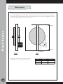
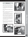
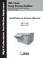
High Performance Ventilation Equipment
PRO-C Series
Energy Recovery Ventilator
For Carrier® HJ, TM and TF Rooftops
(Sizes 3 to 12.5 ton)
Installation & Owners Manual
PRO-C-1000
PRO-C-2400
Table of Contents
PRO-C Series .................................................................................................................................................................................... 1
How it Works .................................................................................................................................................................................... 1
Model Description ........................................................................................................................................................................... 2
Definitions......................................................................................................................................................................................... 2
Receiving & Inspection ................................................................................................................................................................... 3
Overall Dimensions ......................................................................................................................................................................... 3
Storage ............................................................................................................................................................................................... 3
Lifting Technique ............................................................................................................................................................................. 3
Installation ......................................................................................................................................................................................... 4
Linkup ................................................................................................................................................................................................ 4
P ro-C S e r i e s
Support .............................................................................................................................................................................................. 7
Supply/Exhaust Airflow Dampers................................................................................................................................................ 8
Controls ............................................................................................................................................................................................. 9
3Ø Circuit Diagram, PRO-C-1000 .............................................................................................................................................. 11
3Ø Circuit Diagram, PRO-C-2400 .............................................................................................................................................. 12
1Ø Circuit Diagram, PRO-C-1000 - PRO-C-2400 ................................................................................................................... 13
3Ø Electric Preheat Frost Protection Circuit Diagram ........................................................................................................... 14
1Ø Electric Preheat Frost Protection Circuit Diagram ........................................................................................................... 14
Segregated Exhaust Adapter Dimensions.................................................................................................................................. 15
Wheel Cassette................................................................................................................................................................................ 16
Electric Preheat Layout ................................................................................................................................................................. 17
Unit Arrangement & Dimensions ............................................................................................................................................... 18
Maintenance .................................................................................................................................................................................... 19
Belts .................................................................................................................................................................................................. 20
Installation ....................................................................................................................................................................................... 21
Alternative Installation Method ................................................................................................................................................... 21
Retensioning ................................................................................................................................................................................... 21
Contact Information ..................................................................................................................................................................... 22
©
2001-2007 ERV Systems®. All rights reserved.
The information in this technical guide is furnished for informational use only, is subject to change without notice, and should
not be construed as a commitment by ERV Systems. ERV Systems assumes no responsibility for any errors that may appear in
this technical guide.
No part of this publication may be reproduced, stored in a retrieval system or transmitted, in any form or by any means, electronic,
mechanical, recording, or otherwise, without the prior written permission of ERV Systems.
ERV Systems and the ERV System’s logo are registered trademarks.
i
How It Works
The PRO-C Series Energy Recovery Ventilator is an outdoor
air preconditioner specifically designed to reduce the energy
required to cool or heat the outdoor air by as much as 80
percent. The PRO-C also allows the Carrier® 3 through 121/2 ton HJ, TM and TF roof top air-conditioner systems to
effectively and economically accommodate the three-to-four
fold increase in outdoor air quantities, which is recommended
by the ASHRAE Standard 62, Ventilation for Acceptable
Indoor Air Quality. This unique capability allows both
new and existing buildings to benefit from healthy indoor
environments.
A PRO-C is designed to improve humidity control when
combined with the Carrier rooftop equipment. Because
the unit preconditions the incoming air to the packaged
equipment, the required refrigeration capacity can be reduced
by as much as 50 percent. Thus, the costs of the PRO-C
and its installation are typically offset by the reduced size of
the Carrier system. Generally, any first cost premium is paid
back within the first year of operation.
The PRO-C Series is a packaged system which includes
supply and exhaust air fans, outdoor and return air filter
and a TEC total energy recovery wheel. The TEC wheel
recovers both sensible (temperature) and latent (moisture)
energy; it cools and dehumidifies the outdoor air during the
cooling season, while heating and humidifying the outdoor
air in the heating season.
The TEC wheel utilizes a fluted aluminum substrate
which is uniformly coated with a fast-acting, adsorbent
desiccant. As the transfer media slowly rotates between the
outdoor and exhaust airstreams, the higher temperature air
gives up its sensible energy to the aluminum. This energy is
then given up to the cooler airstream during the second half
of the revolution. (See Figure 1.)
Just as the temperature is captured and released, so is the
moisture. TEC’s desiccant coating has an enormous internal
surface area and a strong attraction for water vapor. Since the
opposing airstreams have different temperature and moisture
contents, their vapor pressures differ. This difference causes
the transfer of latent energy.
Figure 1. An inside view of the PRO-C ventilator with typical
operating conditions during the cooling (C) and heating (H)
season respectively.
P ro-C S e r i e s
The PRO-C Series
Exhaust Air
90°F, 99 gr/lb (C)
21°F, 9 gr/lb (H)
Outdoor Air
95°F, 110 gr/lb (C)
5°F, 4 gr/lb (H)
Supply Air
80°F, 76 gr/lb (C)
54°F, 25 gr/lb (H)
Return Air
75°F, 65 gr/lb (C)
70°F, 32 gr/lb (H)
1
Model Description
On the front of the PRO-C is an identification label (Figure
2). The specifications on the label correspond to the
actual unit. The model number PROC-1000 refers to the
nominal air volume (in cfm) that the PRO-C unit is capable
of supplying.
8
Outdoor air – The fresh outside air that is being drawn
in to the energy recovery wheel. Once it passes through
the wheel it becomes the supply air.
9
Return air – Air from the indoor space that is pulled
through the energy recovery wheel. Once it passes
through the wheel it is referred to as exhaust air.
10
Rotor – The media-filled wheel that rotates. It
transfers heat energy and water vapor from one ducted
airstream to the other. Often, the rotor will be referred
to as a wheel.
11
Seal – The soft material that closely surrounds the
rotor to limit the amount of bypass air around the
rotor.
12
Supply air – Air provided to the indoor space.
Outside air that passes through the energy recovery
wheel becomes supply air.
13
Unit – Used frequently throughout this manual to
mean the TEC Energy Recovery Wheel and attendant
components such as cabinets, motors, fans and other
parts that work together to make an effective energy
recovery product.
14
Wheel – Refers to the rotating wheel containing the
coated media. The stationary framework supporting
the wheel is the wheel cassette.
P ro-C S e r i e s
Figure 2. Typical PRO-C nameplate with electrical data.
Definitions
1
Adsorption – The physical bonding of water vapor
on the surface of the desiccant.
2
Cassette – The framework supporting the wheel. (See
also Wheel.)
3
Desiccant – A naturally occurring or man-made
material with a high affinity for water vapor. SEMCO
uses a total energy composite desiccant material which
recovers equal sensible and latent energy.
4
Enthalpy wheel – A common term used to describe
all rotating, wheel-shaped heat transfer devices that
exchange sensible (temperature) and latent (water
vapor) energy from one airstream to another. The
word, enthalpy, means heat content or total heat. The
term, enthalpy exchanger, may also be used.
Figure 3. Typical PRO-C unit with components highlighted
per definitions above.
8
5
12
1
6
14
2
5
Exhaust air – The air from indoors that passed
through the energy recovery wheel and is being ducted
outdoors.
6
Heat wheel – This generally describes all rotating
devices which transfer only sensible energy.
7
Media – The corrugated material inside the wheel.
13
3
4
7
10
2
9
11
Receiving & Inspection
Storage
Upon delivery, confirm that the quantity and model(s)
received matches the Bill of Lading. If there is any
discrepancy, immediately notify ERV Systems.
Inspect the skidded PRO-C(s) for signs of damage. If
damage is suspected, sign the Bill of Lading “damaged.” If
no visible damage is apparent, the unit should be properly
lifted and stored until installation.
While skidded, the PRO-C can be lifted by a forklift
using the skid. Once removed from the skid, lifting must
only be performed with spreader bars, cable and hooks. Do
not attempt to lift the PRO-C by grasping the hoods.
If the PRO-C is to be stored for any time before installation,
it must be protected from the weather. Indoor storage is
recommended. The unit has openings provided for ducting.
These openings make the internal equipment (motors,
belts, fans and insulation) vulnerable to inclement weather
conditions (prior to installation) and can cause standing
water to accumulate inside the enclosure. This is to be
absolutely avoided.
Lifting Technique
Overall Dimensions
Model
L
(in)
H
(in)
W
(in)
Net
Weight*
(lbs)
PRO-C-1000
47.86
30.19
31.38
350
PRO-C-2400
54.75
38.81
40.38
475
Figure 4. Correct lifting technique using spreader bars.
*The package weighs approximately 100 lbs. more than
the net weight.
padding
padding
W
L
padding
P ro-C S e r i e s
Table 1. Weights & Dimensions
When rigging the PRO-C, spreader bars must be used.
Padding must be inserted between the straps and the unit
to avoid scratching the paint. Lifting holes are provided at
four points located on the base perimeter of the PRO-C
unit. The weight shown in Table 1 may be used as maximum
weight for rigging.
H
NOTE:
Prior to starting unit:
1. Open access door
2. Remove loose parts shipped inside.
3
P ro-C S e r i e s
Installation
4
Installation of the PRO-C unit is a relatively simple
procedure, but should be undertaken in a methodical fashion,
following the directions outlined in this manual.
The installation location should be chosen to provide
easy, convenient access. As with all mechanical equipment,
routine maintenance and inspection is necessary. Avoid
locations that are near or downwind of smoke, fumes or
exhaust outlets of other equipment. The front access panel
should have clearance space equal to the depth of the unit
to allow for service.
Once the installation location is determined, the PROC should be un-skidded and closely examined for exterior
damage. Any defects or problems should be reported to
ERV Systems immediately.
After the exterior of the PRO-C is checked for obvious
damage, the front panel can be removed and the interior
checked. Inspect the interior of the unit for any damage.
The ERV Systems energy recovery wheel is mounted
vertically inside the PRO-C unit. Verify that the wheel can be
spun by hand, clockwise from the left. The motor and belt
arrangement that turn the wheel are visible next to the wheel
at the access panel opening. The motor wires running to
the control panel are attached by a quick release disconnect.
The quick disconnect must be separated before sliding out
the wheel cassette. The wheel cassette need not be moved
for installation or hookup, but it can be pulled out for easy
maintenance and inspection purposes as instructed on page
19.
The unit identification tag is located on the electrical
cabinet. It states the electrical requirements for the unit. The
main power connection to the unit should be made on the
control panel inside of the electrical cabinet (see the electrical
diagrams on pages 11-13). Make sure the power provided
to the installation site matches that required by the unit.
Note and verify that the voltage/phase/capacity needed and
provided are the same. Actual line voltage needs to be within
+/- 5% of the rated voltage for the unit to operate properly.
If the unit has been ordered with electric preheat, it
is shipped installed and the unit ID tag is located on the
heater. The main power connection to the unit is made at
the electric coil instead of the unit control panel (see the
electrical diagram on page 14).
Follow the linkup instructions provided on page 6.
Verify that the PRO-C is supported as instructed on page
5, if required.
After installation, attach the outdoor air hood and the
exhaust hood using the alignment holes on the unit. Note
that if the alignment holes are not used the unit may not
function properly. Units with an electric preheat require that
the outdoor air hood be centered on the heater opening.
Optional controls can be set and adjusted (see instructions
on pages 9 & 10). The outdoor and exhaust dampers can
be adjusted after the unit has been test run, as shown on
page 8.
Linkup
All materials required for installing the unit are provided:
Materials Supplied:
• Gasket
• Caulk
• #12 TEK screws
• PRO-C Support Angle
• Return Air Scoop
• Supply Air & Exhaust Air Hoods
PRO-C-1000 Installation Instructions:
1. Remove protective plastic from the Supply Air and
Return Air openings.
2. Within the Supply Air opening, remove all items
(manuals & parts).
3. Remove the screws from the roof of the Carrier unit,
lift, and block.
4. Remove the end panel of the Carrier unit.
5. Install the PRO-C support angle to the base of the
carrier unit. (9 screws)
9. Lower the roof of the carrier unit so that it covers the
top edge of the PRO-C unit. Install a minimum 3 #12
Tek screws across the top flange of the Carrier unit.
3 Tek
screws
6. Install the return air scoop to the return air opening of
the PRO-C unit.
10. If included, place the pedestal support at end of the
PRO-C unit, opposite the Carrier Unit. The pedestal
support is adjustable from 9” to 14”.
11. Caulk the left and right vertical seams on the Carrier
unit as shown below.
12. Install the Outside Air and Exhaust Air hoods on the
PRO-C unit.
NOTE: Rooftop unit filter access will be through the
return air access panel (See Figure 5a.)
P ro-C S e r i e s
7. Install the gasket to the left, right, and bottom facing
edges of the PRO-C unit.
8. Bring the units together and set into place.
5
PRO-C-2400 Installation Instructions:
5. Install the PRO-C support angle to the base of the
carrier unit.
1. Open the fan door of the PRO-C unit and remove all
items (manuals & parts).
6. Install the right side angle trim to the Carrier unit and
secure with screws.
P ro-C S e r i e s
2. Remove protective plastic from the Supply Air and
Return Air openings.
7. Install the bottom angle trim to the PRO-C unit.
3. Remove the screws from the roof of the Carrier unit.
Lift roof and block.
4. Remove the end panel of the Carrier unit.
6
8. Install the return air scoop to the return air opening of
the PRO-C unit.
9. Install the gasket to the left and right facing edges of
the Carrier unit.
Support
The PRO-C unit is designed to support off the end of the
Carrier unit. A required optional pedestal support is available from ERV Systems for the PRO-C series. The PRO-C
series should not be installed without the pedestal support.
(See Figure 5a.) This pedestal adjusts in height from 9 to
14 inches.
10. Bring the units together and set into place.
Figure 5a. Installation of the pedestal support is on the front
side of the PRO-C unit.
11. Install the left side angle trim to the Carrier unit and
PRO-C unit and secure with screws.
#!22)%25.)4
02/#3%2)%3
12. Secure the right side angle trim to the PRO-C unit
with the screws provided.
13. Lower the roof of the carrier unit so that it covers the
top edge of the PRO-C unit. Secure with screws and
caulk.
To install the pedestal support, position the PRO-C
on the Carrier unit. Locate the pedestal under the front of
the PRO-C unit as shown. Lock the pedestal to the correct
height with #12 TEK screws. Fasten the top of the pedestal
to the base of the PRO-C with a minimum of 4 #12 TEK
screws. (See Figure 5b.)
P ro-C S e r i e s
2ETURN
!IR
!CCESS
0ANEL
Figure 5b. Side view of the finished installation is shown.
14. If included, place the pedestal support at end of the
PRO-C unit, opposite the Carrier Unit. The pedestal
support is adjustable from 9” to 14”.
15. Install the Outside Air and Exhaust Air hoods on the
PRO-C unit.
NOTE: Rooftop unit filter access will be through the
return air access panel (See Figure 5a.)
7
Supply/Exhaust Airflow Dampers
P ro-C S e r i e s
All PRO-C units have airflow dampers on the outdoor air
intake and exhaust air outlet that are field adjustable.
To adjust the outside airflow damper, turn the unit off and
open the access panel. Locate the outside airflow damper
actuator inside the unit on the right side. Loosen the two
end stops and with a No. 2 Phillips head screwdriver.
Move the stops to the desired positions and retighten the
screws. To test the correct position of the stops, while
depressing the release button on the actuator, move the
damper to the fully open and closed position. Readjust the
stops as necessary. The actuator will automatically open the
damper to the set position whenever the unit is running and
will close the damper to the set position when the remote
unit start/stop (by others) is off. Note, the actuator needs
power to close, therefore it is not recommended that the
unit be turned off by disconnecting the power to the unit.
This may leave the actuator in an open position, which may
not be desirable.
To adjust the exhaust airflow damper, turn the unit off
and remove the nut/bolt stops on both sides of exhaust
hood. Reposition the nut/bolt stops in the desired adjusting
holes and retighten. Be sure to use matching adjusting hole
on both sides of the exhaust hood. Readjust the stops as
necessary to obtain the desired airflow. The exhaust airflow
damper will automatically open to the set position when the
exhaust fan is on, and close when the exhaust fan is off.
%ND3TOP
2ELEASE"UTTON
%ND3TOP
Figure 6. Location of the outside air damper and actuator.
Exhaust Hood
Exhaust Damper
Nut/Bolt Stop
PRO-C Unit
Adjusting Holes
Figure 7. Diagram of exhaust hood damper.
8
Controls
Basic Package
The basic PRO-C unit ships with no controls. The standard
wiring package provides connections for the starting/
stopping of the complete unit, supply fan and the energy
wheel. The connections are shipped with factory jumpers
installed. Remote control of any of these options can
be achieved by removing the correct factory jumper and
installing a contact in its place. The contact should be capable
of handling 24V power at 2 amps (PRO-C-1000) or 3.5 amps
(PRO-C-2400). (See appropriate 1Ø or 3Ø circuit diagram
on pages 11 through 13). It is strongly recommended that
a remote unit start/stop contactor (supplied by others) be
used to turn the unit on and off. This allows the outdoor
air damper to fully close when the unit is off.
60
Return Air RA2
40
Return Air RA1
30
27
20
Exhaust Air EA2
10
Outside
Air OA1
Outside Air OA 2
0
-10 -5
38
Humidity Ratio
50
Example 2:
The return air condition is 70°F and
35% relative humidity (38 gr/lb).
Line RA 2-OA: Frosting occurs at full
recovery at exhaust air condition EA2 .
Therefore, frost preheat is required
to bring the outside air to condition OA2 .
10
1.5
20
30
40
50
20.2
60
80
70
Dry Bulb Temperature (°F)
Figure 8. SMX70 controller as installed on the electric panel.
P ro-C S e r i e s
For applications where the outdoor conditions do not exceed
-10°F and where the indoor design conditions do not exceed
70°F and 25 percent RH, the energy wheel can operate at full
capacity and will not frost. For colder design conditions or
buildings with higher humidity levels, frosting of the wheel
can be prevented by providing a modest amount of preheat
to the outdoor air. The amount of preheat required is small
and is not intended to raise the outdoor air temperature
above the freezing point. It is only necessary to keep the
exhaust air temperature above the dew point. This prevents
condensation on the wheel so that all the moisture transfer
occurs in the vapor phase.
The preheat control option includes a finned tube
electric coil mounted on the outdoor air intake of the unit,
an SCR controller and a temperature sensor mounted in the
outdoor air plenum. The temperature for the controller is set
to the minimum temperature of the outdoor air required to
prevent condensation at the design indoor temperature and
humidity. This is done by plotting a line on the psychrometric
chart from the indoor design condition down to the coldest
temperature that does not cause the operating line to
intersect the saturation curve on the chart. As stated above,
for inside conditions of 70°F and 25 percent RH, this
temperature is about -10°F.
Example 1:
The return air condition is 70°F and
25% relative humidity (27gr/lb).
Line RA 1-OA: No frosting occurs at full recovery
(grains of moisture per pound of dry air)
Optional Electric Preheat Frost Control
9
The stop/jog economizer option is used during moderate
outdoor air temperatures to stop the recovery wheel. The jog
function is included to allow the wheel to rotate periodically
to self-clean.
When the outdoor temperature is between 55°F (the
cooling coil supply air temperature) and 75°F (the space
return air temperature) the wheel will raise the outdoor air
temperature which will add slightly to the space sensible load.
At the same time, if the outdoor humidity level is higher than
the space humidity level, the recovery wheel will dehumidify
the fresh air slightly reducing the space latent load. If the
local climate is such that these intermediate temperature days
occur mostly at moderate humidity conditions, the stop/jog
economizer can eliminate the heating of the outdoor air and
provide some free cooling to the space.
The stop/jog economizer consists of a temperature
sensor and a circuit board with dip switch selection of
temperature and stop/jog times. When the outdoor
temperature is in the range between the two setpoints, the
timer relay operates the wheel for approximately 30 seconds
in every 30 minutes.
The SMX70 board also has the ability to put the wheel
in stop/jog mode when the outdoor air temperature drops
below a preset value. This is a lower cost option than the
electric preheat. It also has the disadvantage in supplying
untreated outdoor air into the ventilation system whenever
the stop/jog activates.
Optional Rotation Detector Sensor
A lower cost solution to frost protection is to use a thermostat
to turn the entire ventilation unit off during periods when
the air is below the calculated frosting temperature. This
should only be used in non-critical ventilation applications
as no outdoor air will be supplied when the unit is switched
off by the thermostat.
STOP/JOG TEMPERATURE SETPOINTS (DEG. F)
DDDDDDDD
UDDDDDDD
DUDDDDDD
UUDDDDDD
DDUDDDDD
UDUDDDDD
DUUDDDDD
UUUDDDDD
DDDUDDDD
UDDUDDDD
DUDUDDDD
UUDUDDDD
DDUUDDDD
UDUUDDDD
40
41
42
43
44
45
46
47
48
49
50
51
52
53
DUUUDDDD
UUUUDDDD
DDDDUDDD
UDDDUDDD
DUDDUDDD
UUDDUDDD
DDUDUDDD
UDUDUDDD
DUUDUDDD
UUUDUDDD
DDDUUDDD
UDDUUDDD
DUDUUDDD
UUDUUDDD
54
55 LOW
56
57
58
59
60
61
62
63
64
65
66
67
DDUUUDDD
UDUUUDDD
DUUUUDDD
UUUUUDDD
DDDDDUDD
UDDDDUDD
DUDDDUDD
UUDDDUDD
DDUDDUDD
UDUDDUDD
DUUDDUDD
UUUDDUDD
DDDUDUDD
68
69
70
71
72
73
74
75 HIGH
76
77
78
79
80
FROST SETPOINTS (DEG.F)
DISABLED
-14
UDDUDDDD
-13
DUDUDDDD
-12
UUDUDDDD
-11
DDUUDDDD
-10
UDUUDDDD
-9
DUUUDDDD
-8
UUUUDDDD
-7
DDDDUDDD
-6
-5
-4
-3
-2
-1
0
1
OFF/ON TIME*
ON TIME
OFF TIME
(SECONDS)
(MINUTES)
5 DDDD DDDD 0.1 (TEST)
10 UDDD UDDD 10
15 DUDD DUDD 20
20 UUDD UUDD 30
25 DDUD DDUD 40
30 UDUD UDUD 50
35 DUUD DUUD 60
40 UUUD UUUD 70
45 DDDU DDDU 80
50 UDDU UDDU 90
55 DUDU DUDU 100
60 UUDU UUDU 110
65 DDUU DDUU 120
70 UDUU UDUU 130
75 DUUU DUUU 140
80 UUUU UUUU 150
*ON TIME IS SWITCH POSITION 1,2,3,4
*OFF TIME IS SWITCH POSITION 5,6,7,8
UDDDUDDD
DUDDUDDD
UUDDUDDD
DDUDUDDD
UDUDUDDD
DUUDUDDD
UUUDUDDD
DDDUUDDD
UDDUUDDD
HIGH FROST
DDDDDDDD
UDDDDDDD
DUDDDDDD
UUDDDDDD
DDUDDDDD
UDUDDDDD
DUUDDDDD
UUUDDDDD
DDDUDDDD
2
3
4
5
6
7
8
9
10
12345678
Wheel Only Frost Protection
Typically Disabled
Upper Stop/Jog Economizer
Setpoint (Typically 75°F)
LOW
The SMX70 stop/jog economizer board can be supplied
with a motion detector to monitor the rotation of the energy
recovery wheel. The sensor is a hall effect device that senses
the passage of a small magnet on the perimeter of the rotor. When the sensor fails to register any wheel rotation - it
requires a signal every 20 seconds or 10 minutes depending
on the mode of operation - it energizes the alarm terminal
(24 VAC, .3 amp max) of the SMX70 board. This can be
used to operate a relay (to be supplied by others) for remote
indication of the alarm. The sensor will not create a false
alarm when the SMX70 controller is in stop/jog mode.
The alarm resets itself once the wheel begins to turn
or the system is shut off and restarted.
Please note that the triac output for the alarm signal
requires a load, such as a contactor coil, to operate. This
output may not register on a digital multimeter without the
load, or may cause a lamp with no limiting resistor to light
dimly.
Thermostat Frost Protection
10
Figure 9. SMX70 controller as installed on the electric
panel.
Lower Stop/Jog Economizer
Setpoint (Typically 55°F)
TIME
P ro-C S e r i e s
Optional Stop/Jog Economizer And Wheel
Frost Protection (SMX70 Controller)
Stop/Jog Times
(Typically 30s on,
30 minutes off.)
UP
DOWN
SMX70 CONTROLLER
Figure 10. SMX70 Controller settings.
3Ø Circuit Diagram, PRO-C-1000
USE COPPER
CONDUCTORS
ONLY
Line Power
480/240-208/3/60
Disconnect (by others)
*See Note 2
1CR
H3
Supply Fan
Motor
M
Exhaust Fan
Motor
M
Wheel
Motor
H2
2CR
H3
2CR
H1
3CR
H3
3CR
H2
3CR
H1
H2
208/240/480 - 24VAC
40VA UL Cl 2 XFMR
Supply & Exhaust Fan Remote Start/Stop
(by others, factory jumpered)
H1
1
3
2
2
Optional Thermostat Frost Control
*See Note 4
4
2CR
5
2
1
4
1CR
4
3CR
P ro-C S e r i e s
M
1CR
Notes:
1) All dashed lines indicate field wiring unless
otherwise noted.
2) Electric Preheat: If electric preheater is ordered,
the power wiring is factory installed from electric
preheater to Preconditioner Panel and includes a
disconnect at the preheater, (See specifications
and circuit diagram on electric preheater for
information on sizing and connecting supply
power.)
3) Alarm output: One triac-switch to drive a
contactor (by others), 24VAC, 0.3 amps max.
4) If no options are ordered, terminals 1 & 2
are shipped with jumper installed.
5) Remote unit start/stop (by others) may be
any isolated contact, to prevent interconnection
of class 2 outputs, suitable for 24 VAC @ 2
amps.
6) If Relay is ordered, terminals 1 & 2 will
be wired to the N.O. relay mounted on the
electrical panel. Power wiring for the relay
coil is from the Carrier unit and is installed
by others.
Optional Relay
*See Note 4,6
Remote Unit Start/Stop (by others)
*See Note 4,5
5
2
4
Outdoor Air Damper Actuator:
Belimo
Optional Stop/Jog Controller:
Model SMX70
Thermistor Sensor
310-1865 Assembly
RED
BLK
GRN
Wheel Remote Start/Stop
(factory jumpered if optional
SMX70 controller not included)
BELIMO
T2
T1
GRN
L1
4
2
ALARM
5
WHEEL
Optional
Motion Detector Sensor
310-1875 Assembly (observe polarity)
COM
Aux. Rotation Alarm (not used)
(See Note 3)
+
+
1
2
3
BLK
RED
WHT
4
1
2
Tightening Torque
For
Slotted Screws
AWG Size
IN-LB
18-10
20
8
25
6-3
35
11
3Ø Circuit Diagram, PRO-C-2400
Line Power
480/240-208/3/60
USE COPPER
CONDUCTORS
ONLY
Disconnect (by others)
*See Note 2
Notes:
1) All dashed lines indicate field wiring unless
otherwise noted.
2) If electric preheater is ordered, the power
wiring is factory installed from electric preheater
to Preconditioner Panel and includes a disconnect
at the preheater. (See specifications and circuit
diagram on electric preheater for information
on sizing and connecting supply power.)
1CR
H3
1CR
H2
M
Supply Fan
Motor
1CR
H1
3) Alarm output: One triac-switch to drive a
contactor (by others), 24VAC, 0.3 amps max.
4) If no options are ordered, terminals 1 & 2
are shipped with jumper installed.
2CR
H3
2CR
P ro-C S e r i e s
H2
M
5) Remote unit start/stop (by others) may be
any isolated contact, to prevent interconnection
of class 2 outputs, suitable for 24 VAC @ 3.5
amps.
Exhaust Fan
Motor
2CR
H1
6) If Relay is ordered, terminals 1 & 2 will
be wired to the N.O. relay mounted on the
electrical panel. Power wiring for the relay
coil is from the Carrier unit and is installed
by others.
3CR
H3
3CR
H2
M
Wheel
Motor
3CR
H1
H2
208/240/480 - 24VAC
75VA UL Cl 2 XFMR
Supply Fan Remote Start/Stop
(by others, factory jumpered)
H1
1
3
2
2
Optional Thermostat Frost Control
*See Note 4
4
1CR
4
2CR
1
2
5
Optional Relay
*See Note 4,6
4
3CR
Remote Unit Start/Stop (by others)
*See Note 4,5
Wheel Remote Start/Stop
(factory jumpered if optional
SMX70 controller not included)
2
5
4
Outdoor Air Damper Actuator:
Belimo
Optional Stop/Jog Controller:
Model SMX70
Thermistor Sensor
310-1865 Assembly
RED
BLK
GRN
T1
GRN
L1
4
2
ALARM
5
WHEEL
Optional
Motion Detector Sensor
310-1875 Assembly (observe polarity)
COM
Aux. Rotation Alarm (not used)
(See Note 3)
Tightening Torque
For
Slotted Screws
12
BELIMO
T2
AWG Size
IN-LB
18-10
20
8
25
6-3
35
4
1
2
+
+
1
2
3
BLK
RED
WHT
1Ø Circuit Diagram, PRO-C-1000 - PRO-C-2400
53%#/00%2
#/.$5#4/23
/.,9
,INE0OWER
#2
(
-
3UPPLY&AN
-OTOR
-
%XHAUST&AN
-OTOR
-
7HEEL
-OTOR
#2
(
#2
(
#2
(
#2
(
#2
(
3UPPLY&AN2EMOTE3TART3TOP
BYOTHERSFACTORYJUMPERED
6!#
6!5,#L8&-230
6!5,#L8&-230
/PTIONAL4HERMOSTAT&ROST#ONTROL
3EE.OTE
#2
#2
#2
/PTIONAL2ELAY
3EE.OTE
P ro-C S e r i e s
.OTES
!LLDASHEDLINESINDICATEFIELDWIRINGUNLESS
OTHERWISENOTED
)FELECTRICPREHEATERISORDEREDTHEPOWER
WIRINGISFACTORYINSTALLEDFROMELECTRICPREHEATER
TO0RECONDITIONER0ANELANDINCLUDESADISCONNECT
ATTHEPREHEATER3EESPECIFICATIONSANDCIRCUIT
DIAGRAMONELECTRICPREHEATERFORINFORMATIONON
SIZINGANDCONNECTINGSUPPLYPOWER
!LARMOUTPUT/NETRIACSWITCHTODRIVEA
CONTACTORBYOTHERS6!#AMPSMAX
)FNOOPTIONSAREORDEREDTERMINALSARE
SHIPPEDWITHJUMPERINSTALLED
2EMOTEUNITSTARTSTOPBYOTHERSMAYBEANY
ISOLATEDCONTACTTOPREVENTINTERCONNECTIONOF
CLASSOUTPUTSSUITABLEFOR6!# AMPS
30ORAMPS30
)F2ELAYISORDEREDTERMINALSWILLBEWIRED
TOTHE./RELAYMOUNTEDONTHEELECTRICALPANEL
0OWERWIRINGFORTHERELAYCOILISFROMTHE#ARRIER
UNITANDISINSTALLEDBYOTHERS
$ISCONNECTBYOTHERS
3EE.OTE
2EMOTE5NIT3TART3TOPBYOTHERS
3EE.OTE
/PTIONAL3TOP*OG#ONTROLLER
-ODEL3-8
/UTDOOR!IR$AMPER!CTUATOR
"ELIMO
4HERMISTOR3ENSOR
!SSEMBLY
2%$
",+
'2.
4
7HEEL2EMOTE3TART3TOP
FACTORYJUMPEREDIFOPTIONAL
3-8CONTROLLERNOTINCLUDED
"%,)-/
4
'2.
,
!,!2-
7(%%,
#/-
",+ 2%$ 7(4
/PTIONAL
-OTION$ETECTOR3ENSOR
!SSEMBLYOBSERVEPOLARITY
!UX2OTATION!LARMNOTUSED
3EE.OTE
4IGHTENING4ORQUE
&OR
3LOTTED3CREWS
!7'3IZE
).,"
13
3Ø Electric Preheat Frost Control Circuit Diagram
cutout
airflow switch
SC
Line Power
208-240V/480V/3¯/60H
P ro-C S e r i e s
remote duct stat
with set point adjuster
F1
1
F2
2
3
SC
SC
SC
L1
H1
L2
H2
L3
H3
manual cutoff
fuse
Solitech
master controller
H1 H2 H3
delta- or wye-connected
electric heat coils
to main panel
on SP unit
1Ø Electric Preheat Frost Control Circuit Diagram
cutout
airflow switch
remote duct stat
with set point adjuster
F1
1
F2
2
Line Power
208-240V/1¯/60Hz
3
SC
H1
L2
SC
fuse
H1
H2
to main panel
on SP unit
14
L1
L3
H3
Solitech
master controller
electric heat coil
SC
Segregated Exhaust Adapter Dimensions
T
US
HA
EX AIR
B
D
A
RIC
C
ET
M
ISO
UNIT SIZE
A
B
C
D
PRO-C-1000
10.83
10.83
2.52
10.83
PRO-C-2400
14.76
14.76
3.23
14.76
W
VIE
P ro-C S e r i e s
SS
ACCE
ING
OPEN
2.3
TY 2"
PIC
AL
15
Wheel Cassette
The wheel cassette can be serviced through the front panel. The cassette can be slid out for easy access. To remove
the cassette, unplug the leads to the wheel drive motor, then remove the (2) tek screws located near the opening. This
will then allow you to pull the cassette out of the unit through the access door. If the unit is equipped with a rotation
sensor, it must be removed prior to sliding the cassette out.
P ro-C S e r i e s
Screw
MOTOR
Screw
1/2" deflection
FRONT
Remove links from the belt to tension. The belt
should deflect only 1/2” at the center of free area.
16
SIDE
MODEL
PRO-C-1000
PROD-C-2400
PRO-C-1000
4L/”A”
4L/”A”
PRO-C-2400
76”
106”
Electric Preheat Layout
R
NE
IO
DIT AL
N
O RIC
EC
T
PR LEC EL
E
N
PA
-C
Un
it
PR
EH
EA
EC TER
T
PA RICA
NE
L
L
EL
AIR
FL
OW
L
B
W
AIRFLOW
H
A
AIRFLOW
B
P ro-C S e r i e s
Pro
C
D
SIDE VIEW
C
PLAN VIEW
Model#
Dimensions (inches)
W
H
L
A
B
C
D
PRO-C-1000
24.37
16
14
20
1
2
8
PRO-C-2400
30.5
20.37
14
20
1
2
8
17
Unit Arrangement & Dimensions
T
US
HA
EX AIR
SU
P ro-C S e r i e s
D
ESS
ACC
NING
OPE
PP
AIR LY
RE
TU
AIR RN
*
C
B
G
F
L
ICA
TR L
EC
EL PANE
A
E
ID
TS
OU AIR
FO
R F RE
AN MO
FO
R F A AC VAB
SE AN C CE LE
RV A CE SS PA
ICE CC SS (P NE
CL ESS DO RO- L
EA (P OR C-1
RA RO
00
NC -C
0)
E = -24
0
24 0)
"
E
Dimensions (inches)
Model#
Net Wt.
(lbs.)
A
B
C
D
E
PRO-C-1000
350
30.188
47.875
31.375
11.75
17.0
17
2.0
PRO-C-2400
475
16.3
44.4
8.7
31.0
8.6
22.6
2.0
Note: Dimensions F & G represent approximate unit center of gravity.
*Service clearance is equal to “C” dimensions.
18
F
G
Maintenance
Filters – The PRO-C utilizes one-inch deep industrial
grade aluminum mesh filters. The filters can be removed
and washed. (See Figure 13.) We suggest that the filters
be washed or replaced a minimum of once every four
months. Replacement filters are readily available through
ERV Systems, locally through HVAC supply distributors
or McMaster-Carr.
Seals – Surrounding the rim of the wheel is a brush seal.
Do not tamper with this seal. No maintenance of the seal
is required.
Figure 12. Prior to sliding our the wheel cassette, the wheel
motor quick release must be disconnected.
P ro-C S e r i e s
Media – For normal inspection and maintenance, the wheel
cassette may be pulled out (like a drawer) of the metal
enclosure of the unit. (See Figure 14.)
Because ERV Systems’ heat wheels use laminar flow
technology to resist plugging and the accumulation of dust
particles, cleaning is usually not necessary. Constant backflushing occurs due to incoming and outgoing airstreams
that move through media flutes to keep them clean. As the
media moves constantly from one airstream to the other,
most dirt is blown away. Some applications may require
occasional rotor cleaning; those receiving a great particle
load, for example. Under these circumstances, the media
may be cleaned with a vacuum, pressurized air or hot water.
However, detergents or solvents are not recommended. They
may degrade the materials used to bind the desiccant to the
aluminum surface in the media.
Belts – The wheel drive system utilizes a PowerTwist®
Plus™ belt. Periodic adjustment of the belt will be necessary.
We suggest the belt be checked for sufficient tension at a
minimum of once every six months. Take care to follow the
directions on pages 20 and 21.
Figure 13. After disconnecting the wheel motor quick release, the upper and lower TECK screws must be removed.
Figure 11. Replacing the return air filter.
Figure 14. The wheel cassette is removable through the
service door.
19
Belts
How to Measure, Assemble and Install PowerTwist® Plus™ V-Belts
PowerTwist® PlusTM V-Belts are supplied by Fenner
Drives. For additional information about the company,
please refer to the contact information on page 22.
Measuring the Belt
P ro-C S e r i e s
Pull belt tight around sheaves to check hand tight
length, overlapping the last two tabs with two holes
in matching links as shown in Figure 15. Count the
number of links and remove one link for every 24 of
O/3L, A/4L and B/5L sections and one link for every 20
of C section. This gives the correct installed belt length and
will ensure optimum belt tension when running.
Figure 15. Measuring the belt.
Note: Every tenth link is designated with an arrow. For
multiple belt drives, ensure that each belt has the same
number of links.
1. Hold belt upside down. Bend
back as far as possible and
hold with one hand. Twist one
tab 90° parallel with slot.
2. Pull end of link over tab.
3. Rotate belt end with tab
90°.
4. Pull belt end through two
links.
1. Hold belt with tabs pointing
outward.
2. Place end tab through two
links at once.
3. Flex belt further and insert
second tab through end link by
twisting tab with thumb.
4. Ensure tab returns to position
across belt. Reverse belt so
tabs run inside.
Note: Turn belt inside out (as shown above) to ensure easy assembly and disassembly.
20
Installation
1. Turn belt with tabs to the inside before installing.
2. Determine direction of drive rotation.
3. Align belt directional arrow with drive rotation.
4. Fit belt in nearest groove of smaller sheave.
5. Roll belt onto larger sheave, turning the drive slowly. Belt
may seem very tight; this is okay. DO NOT jog motor.
6. Check to see all tabs are still in their correct position and
are not twisted out of alignment.
Alternative Installation Method
1. Set motor to mid-position of adjustment range and
mark base clearly.
2. Determine required belt length as in “Measuring
Belt Length.”
3. Push motor forward to minimum center distance.
P ro-C S e r i e s
7. For multiple belt drives, work belt from groove to groove.
On particularly wide drives, it may be easier to install
half the belts from the inboard side and half from the
outboard. Note: With drive ratios around 1:1, it may be
necessary to add back one link to allow belts to be rolled
on. This does not apply if using Alternative Installation
Method.
4. Install belts as in “Installation.”
5. Pull motor back to previously marked mid-position.
Retensioning
Like all high performance V-belts, PowerTwist® Plus™ VBelts require the maintenance of correct drive tension to
operate efficiently. Experience indicates that drive tension
should be checked after 24 hours running at full load. A
retension may be necessary depending on the severity of the
drive. Any initial belt stretch is then taken up. Subsequently,
belt tension should be checked periodically and adjusted
when necessary.
21
Contact Information
How to Reach ERV Systems
You can reach ERV Systems by phone, fax or e-mail.
ERV Systems
PO Box 1797
Columbia, MO 65205-1797
Phone: (573) 886-5400
Fax: (573) 886-5401
[email protected]
www.ervsystems.com
P ro-C S e r i e s
How to Reach Fenner Drives
22
Fenner Drives
311 W. Stiegel St.
Manheim, PA 17545-1010
Phone: (800) 243-3374
Fax: (717) 665-2649
PO Box 1797
Columbia, MO 65205-1797
(573) 886-5400
(573) 886-5401 fax
www.ervsystems.com
[email protected]
OG 002 0807 1K G