1
ER'S
MANUAL
MODEL NO.
257.796050
ADJUSTABLE HANDLE
WEED AND GRASS TRIMMER
DOUBLE INSULATED
• Assembly
CAUTION:
• Operating
• Repair Parts
Read RULES for
Safe OPERATION
and INSTRUCTIONS
Carefully
Sold
r
by SEARS,.
PROTECTED UNDER ONE OR MORE OF THE FoLLOWiNG
U:S; PATENTS: 4, 189, 833; 4, +269,372; 4, 490, 9t0.
:ROEBUCK
AND
CO.
Chicago.
IL.+ 60684
U.S,A.
:
,
FORM 88-588+00
Re,/. C 0687
ifth_sElectricWeedw_cker
failstoperformproperly
dueto a defectin materialor workrn_.ship
withinoneyearfrom the dateof purchase,Searswillrepairit, fre_of eha_e.
if thisElectricWesdw_c_er
isusedforCOmmerCial
orrerdalpurposes,
thiSwarranty
appliesforonly
9_ days fromthedateof purchase. This warranty apples On_y whilethisproduct is in usein the
Unite<l_ates.
Warranty service _s available by s_mply contacting the nearest
throughout the United Sta_tes,
Se_
=ore or Service Center
Thiswarrantygivesyouspecificlegalrights,andyoumay_ haw otherdghtewhichva(yfrom
stateto state.
SEARS,ROEBUCKANDCO.,Dept.698/731A,SearsTower.Chicago,
IL60684
IMPORTANT:
SAFETY RULES FOR POWER TOOLS
CAUTION
RULES FOR SAFE OPERATION
16. Store idle Trimmer indoors. When not in use, Trimmer
s!loutd be stored indoors in dry place out of reach of
children.
...... 1: =Keep ha_qds,feet and face clear of rotating line. Do not ........ 17. The automatic line cutter is extremely sharp and care
operate without guard in place.
should be exercised when handling or operating the
2. Always ttse Safety Goggles. Wear at all times when
Trimmer to avoid contact with the cutter.
trimming.
18. KEEP AIR VENTS CLEAR OF DEBRIS.
3. Dress properly. Always wear shoes. DO not operate
Tool while barefoot or when wearing sandals, canvas
DOUBLE INSULATION
or open toed shoes. Use of rubber gloves and safety
Double Insuiation is a concept in saf_y, replacing the stanfootwear is recommended when working outdoors.
dard grounded supply system, in electric power tools. The
Wear long pants to protect your legs.
construction of a double insulated too} affords comparable
4. Keep Children away. Keep spectators at a safe
protection to a properly grounded tool without the necessity
distance.
for using a grounded conductor. The double insulation
system eliminates the need for the usual three wire
! WARNING: To reduce electric shock hazard use only
5.
grounded power cord and grounded supply system.
with an extension cord suitable for ot,'tdooruse, A twoWherever there is electric current in the tool there are two
wi_cord without a ground connecttonmay be used
complete sets of insulation to protect the user. All exposed
silt_ tJie tool is double insulated. C0rdshould be "16
metal parts are isolated from the Internal metal motor
_a_ge0_: heavier to reduce overh,eating:and loss of
Components with protecting Insulation. The lead wires,
_<_weLExtension cord should not exceed100 feet. U.L
switch, etc. with their functional insulation have the added
isled extension cords are available from your nearest
protection of non-conductive sleeving or housings to
complete the double insulation system.
6. To _iey_nt disconnection of power supply cord from
SERVICING OF A TOOL WITH DOUBLE INSULATION
the extension cord during operation, see instructions
REQUIRES EXTREME CARE AND KNOWLEDGE OF THE
wittt:_Figure 4.
SYSTEM AND SHOULD BE PERFORMED ONLY BY A
7. Avoid Dangerous Environment _ Do not use unit in
QUALIFIED SERVICE TECHN|CtANo FOR SERVICE WE
damp or wet areas, or in the vicinity of flammable
SUGGEST YOU RETURN THE TOOL TO YOUR NEAREST
fumes.
AUTHORIZED DEALER FOR REPAIR WHICH WILL BE
8. Don't force this tool tt will Work better a_d safer at the
DONE WtTH OR_GINAL FACTORY REPLACEMENT PARTS.
rate for which it was designed. If motor slows down
{o0 much, pull away and allow un|t to obtain fult speed,
BOX CONTENTS
9. Do not use toot for any job except that for which it is
This box ShOuld contain
intended.
1 257.796050 WEED AND GRASS TRIMMER
10. Do not immerse tool in water or operate rinrain.
1 Ea. 6838-15 REAR GUARD & BLADE ASSY.
1 LOOSE PARTS KIT CONTAINING
11. Don't overreach -- Keep proper footing and balance at
2 E& 1745-2 SCREWS
ait times.
2Ea. 23591 STOP NUTS
12.. Don't abuse cord _ never carry appliance by, cord or
.2 Ea. 1847-4 SCREWS '
! yanki_€ordfrom receptacle. KeeP cord away from beat,
' lEa. 6834_5 ASS!ST HANDLE
oil_,_b_nd sharp edges.
Replace damaged cord
lEa. 683205 PIVOT YOKE
i_mediately.
1 Ea.
HANDLE KNOB
13. Nev_r carry plugged ln appiianse with finger on swltoh.
lEa. 2181 BOLD
2 Ea, 7191-05 HANDLE INSERT
14. DisP.;pnnect toot from the power sUpp!y when not in use
1 Ea. 454526 WASHER
an when making any repairs or i_spections.
lea. 6772-05 FRONT GUARD
15. Mairdain Trimmer with care and fq!loW instructions for
, , l_'_-Ea,
88-588-00 OWNERS MANUAL
replacing o[ rewinding spool.
"
ASSEMBLY INSTRUCTIONS
HANGER
Remove TRIMMER from carton and examine it thoroughly
make sure it is not damaged.
to
Remove
and discard protective
plastic ciips
handle tubes before assembly
of trimmer.
in
inserted
POWERCORD "_
TOOLS NEEDED FOR ASSEMBLY
"
Medium Phillips screwdriver
Adjustable wrench or pliers
LOt_VER
TUgE
REAR GU.AR D
_JTER
TUB
_
6_
A
ATrACH|NG
'
Ft_21Nr 13_J_D
THE ASSIST HANDLE AND TUBES
YOUR
WEEDWACKER
COMES EQUIPPED WITH A
PIVOTING ASSIST HANDLE. THIS FEATURE ALLOWS YOU
ADDITIONAL
FLEXIBILITY AND COMFORT FOR THE
ANGLE OR CUTTING POSITION YOU MIGHT REQUIRE.
--,a'
/
The wire and cabte that is exposed between the tube sections
...2, Slide
the yoke onto the upper
tube (Fig. 1).
_.,
3,
Locate
assist handle
(Fig.of 1)the
andyoke_
replace
will passthethrough
the slotonin the
the yoke
bottom
parts as shown in Rgure 1A.
all"
4,
Slideoutertubesleeveuptowertubeandoveruppertubeunt_!
t_e assembly holes are aligned. BE CAREFUL
NOT TO
PINCH, CUT OR TWIST CABLE AND HARNESS DURING
ASSEMBLY.
5.
Insert screws into the holes and attach locknuts (Fig. 2). Actuate lever to ensure free movement of cable before tightening
screws (see instructinns under "ADJUSTABLE
HANDLE" -PAGE 4).
...... I] F
FIG. 1 A
6. Adjust position of handle to conform to height a_nd arm length
of user. Handle may be adjusted forward or backward as
desired. Assist handle may be rotated or moved up or down
by loosening t_e knob.
ATTACHING
TURN
THE GUARD
TRIMMER
UPSIDE
DOWN,
SLIDE
SECTION
AND FRONT GUARD SECTION
,ON TRIMMER
HOUSING (FIG. 3).
iNSERT
DO
IG.
2 SCREWS
NOT OPERATE
SUPPLIED
TRIMMER
REAR
INTO
AND TIGHTEN
WITHOUT
GUARD
FIG. 2
GUARD
GROOVES
FIRMLY.
RF_R GU/,R=)
1N PLACE.
CAUTION: THE CUTI'ING BLADE MOUNTED IN THE
GUARD ASSEMBLY IS EXTREMELY SHARP AND CARE
SHOULD
BE EXERCISED
WHEN HANDLING
OR
OPERATING
TRtMMER TO AVOID CONTACT
WITH
CUTTER.
FIG. 3
"'
.
i
3
•
KEEP AIR VENT_
OPERATING
BEFORE
INSTRUCTIONS
OPERATING
Before using your WEEDWACKER
Rules for Power Tools.
•
Always
•
Cut to your LEFT s_de.
HOW TO ACTUATE SELF FEEDING
read and understand the Safety
wear SAFETY GOGGLES.
•
Keep people away from you.
•
Inspect the areas you are going to trim for wires, cord and any
string-like
matter to prevent them from getting tangled in the
cutting head.
APPLIANCE
CORD
\
CUTTING LINE
t.
2.
Plug in power cord.
Start motor
3.
Tap the hub light|_, on the-tuff.
Cutting line will advance
automatically while, motor is running.
4.
Repeat step number 3 to advance additional cutting line. The
cutting line will be trimmed automatically by the _ade line cutter while motor is running, so don't "tap out" unneCessarily long
cutting linelengths.
GENERAL TRIMMING
EXTENSION
CORD
For mosttdmmingthe unitis TILTED TO THE LEFTat approximately
30 degrees (as shownbelow).
FIG.5
FIG.4
TIE CORD AS
SHOWN
RETAINING EXTENSION CORD
0 °
To prevent extension cord from
disconnecting
from
appliance cord, tie cords as shown in Figure 4. Devices for
retaining extension cords are also available
from your
nearest Sears store.
MOWING
HOW TO OPERATE
1,
Simplypassyour WEEDWACKER over U'mareas you wish to cut,
keepingthe cuttinghead parallel to the ground.DO NOT use the
usual 30 degree cuing angle when mowing as in lig. 5.
Hotd trimmer in a comfortable upright position and depress
trigger switch.
2.
Bestresultsare accomplished with proper length line and maim
taining full speed. Cut only with the tip of the nylon line.
WHEN OPERATING
1.
2.
ADJUSTABLE HANDLE
Your TRIMMER incorporates
a new adjustable handle
feature which makes trimming and edging in "hard to get at
areas" much easier, The adjust mechanism is located on top
,P* +
\ _
-_f,,he
handle gr,p tit&'.
_F,_.S j..Aake
sure head is on the ground
when adjusting.
The WEEDWACKER will stir up dust particles which may get
into your eyes. Wear safety goggles to prevent this. When you
cut to the LEFT SIDE, your WEEDWACKER will sling particles
FORWARD, away from you. When you cut to the RIGHT SIDE,
it will sling par£[ctesBACK towardyou. ALWAYS CUT TO THE
.LEFT SIDE ONLY..
1. Grasp the lever with. thumb and forefinger and puil
back gently. This will disengage the locking.pin in the
motor housing, and th e handle tube will pivot freely.
:2. Select desired position and release the lever. Tube will
Ioc!_into place automatically.
Your WEEDWACKF_Rcan sting objects with adequate velocity
to cause harm tO others, it wilt ALWAYS sling small particles
of dirt. KEEP PEOPLE AWAY FROM YOU when using your
trimmer just to be safe.
UNE IS TRIMMED AUTOMATICALLY
Your new WEEDWACKER is equipped with a fut]y automatic line
cutter. After a new section of line is fed out, a blade mounted in the
guard will cut the line .to its proper length automatically.
This feature keepsthe line tdmmed to a safe and most efficient cutting length. Always make sure this cutter is wo_'kingefficiently to
achieve the best results.
ADJUSTABLE
LEVER
toAUT,oN-THE
O0, '.G
B .OE
.O0. 0INTHEI
tGUARD
ASSE ,S
SLY
S.ARP
A"DeA" I
JSHOULD
BE EXERCISED
WHEN
HANDLING
/OPE"AT'"
T"'M"ER
TOAVO'O
CO.TAO
VOR|'T"i
4
FIG.6
OPERATING
INSTRUCTIONS (cont'd)
TO REPAIR
cUTTING
BROKEN
LINE
t.
StOp the motor an unplug power cord.
2.
Visible
3.
Hub should be depressed and released while keeping tension
on the cutting line. One inch o_ cutting line should feed each
time the hub is depressed.
4.
If cutting line cannot be retrieved,
SPOOL REPLACEMENT.
cutting fine can be retrieved with needle nosed pliers.
follow instructions under
SPOOL REPLACEMENT
1.
2.
3.
4.
5.
6.
7.
8.
9.
Stop motor and unplug power cord.
Restrain rear plate_pushin took button (located onhub),andtwist
Ilub counter-clockwiseuntil locking bbs disengage.Removehub.
Rereove spool from assembly a_ndremove spring from spool
Rewindspooiinacco_ancewiththeinstructionsincludedherein
(fig. 8) or replace spool as appropriat_
Before reinstalling spooi be sure approximately :3inchesof |ine
exits spool between the two foam pads as shown in fig. 7.
"
Install spring on "TOP SIDE" of spool. Seefig. 7.
insert line thru eyelet in hub assemblyandseat springendonto
center post inside hub assembly.
NOTE: Make sure linedoes notgettmpped underspool, between
the spool and hub assembly.
=
Slide spooland hub assemblyontomotorst=aft.Manlpulate parts
siightiy to obtain proper alignment.Align lockingtabs on hub
assembly with slots in rear plate and insert tabs intostotsuntil
parts bottom, Rotate hubassembly clockwisewhile restraining
the rear plate until all four locking tabs are properlyengaged.
Remove debris from undersideof yourWEEDWACKER.
REWINDING
SPOOL
When rewind_g be sure to wind the line in the direct|on of arrow
indicatedon spool{Fig.8) Plastic is a memory malaria! and the line
should be recoiledformthe original coil to the spool in a way so the
built-in memorytendsto keepthe coilstightto the spool. If you recoil
in tile o_ite
directionthe coils w0uld be 100SOai'_ tend to come
unwound. To secure line to spool, place tape over approx. 11/2"of
!ine, then secure tape to spool. Line must be wound side by side
avoiding crossoveror crisscrossingto insure proper line advancing.
Do not wind more than a total of 40 feet of line onto spool.
IF LINE DOES NOT FEED
1,
Follow instructions 1-3 under "Spool Replacement:'
2.
Check to make sure line is wound in direction indicated
on spool,
Separate strands of tangled Itne or install new line if
t_ecessary,
3.
4.
5.
6.
FIG. 8
RECOMMENDED REPLACEME_
AND ACCESSORIES
inspect foam pad for tears of damage, replace if necessary.
Check spring for damage and proper installation.
Follow instructions 5 thru 11 under "Spool Replacement."
PARTS
Your SEARS WEEDWACKJERuses SPECIALLY TREATED .065
DIAMETER MONORLAMENT NYLON cutting line whichis available
at SEARS STORES AND CATALOG STORES. You may purchase
a fullywoundspoo!(PartNo. 85744) or you may purchasea package
of two 50 foot coils(Part No. 85772) or a large bulk spool of line and
rewind yourpresent spool.
CAUTION: The use of heavier line, different types of line and accessories or attachments other than recommended may be hazardous or cause unit failure.
THE OPERATION OF ANY TRIMMER CAN RESULT IN FOREIG N OBJECTS BEING THROWN
INTO TH E EYES, WHICH CAN'RESULT IN SEVERE EYE DAMAGE. ALVVAYS WEAR SAFETY
GLASSES OR EYE SHIELDS BEFORE COMMENCING POWER TOOL OPERATION. WE
RECOMMEND WIDE VISION SAFETY MASK FOR OVER SPECTACLES OR STANDARD
• .SAFETY GLASSES AVAILABLE AT SEARS RETA L OR CATALOG STORES.
5'
MODEL NO. 257.796050
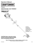
F-.XPLODED VIEW
14"_
31
r
:6
MODEL NO. 257.796050
PARTS
LIST
DOUBLE INSULATED -- WHEN SERVICING USE ONLY IDENTICAL REPLACEMENT PARTS
NO.
!.
2.
3.
4_
5.
6.
7.
8.
9.
10.
11.
12.
13.
14.
15.
16.
17.
18.
19. •
20.
21.
22.
23_
24.
25.
.....
26.
27.
28.
29.
30.
31.
32,
33.
34.
35.
36.
37.
38.
39.
40.
41.-*
42.
43.
44.
45.
46.
-47.
48.
49.
50.
57.
52.
_OrOR 63.
54,
56.
57.
58.
59.
61.
62.
•
PART
NO.
23452
6781
6780_4
6767-55
3272-3
6858
6962
5517-4
6828-1
6777-05
3366
7160.1-28
7683
REE
4872_35
68454
6791
6779-04
'6792 .....
7818-1
2224
6772-05
t937
6838-15
6832-05
2181
6834O5
6833-05
2359-I
6963
78t7
1745-2
6827-7
6826-1
2701
5899
4877.15
22074643
2467-3
1586-2
4868-05
1574-1
1576
4864-15
1847.4
2865-05
2287-3
2276-1
2288
2270-4
747-2
7677
2467
2389-3
2275-1
2260
2278
2280
2277
7191-05
.454526
7182
88-58800
DESCRIPTION
,r_¢ver Cord
Switch Slide
Trigger
Handle R.HJL.H.
Pin, Hinge
Cable and Lever Ass,/
Tube, Upper
Harnes Assy (Incl_ Item 11)
Tube, LOwer
Pivot, R.H./LH.
PC, Bridge Assy.
Housing R.HJLH.
Motor Assy.
Auto Head Ass,/
Air Baffle
Label, Housing Front
Pin, Sleeve
S{'eeve
Spring, Sleeve
Label, Housing Top
Screw, 10-t6 x t Thd Form
Guard, Front
Screw 8-18 11 x 1f2 Thd Form
Guard and Blade Assy
Yoke
Bolt, 7f4-20 x 4 Hex
Assist Handle
Knob, Adjust
Nut, Stop
Tube, Outer
Label, WarninglNameplat_
Screw, 10-24 x 1-1/4 Mech.
Label, Lower HandJe
Label, Upper Handle
Hanger
Drive Adapter
Rear Plate
Washer
Retaining Ring
.Foam Pad
QTY.
1
1
I
1 (set)
1
I
1
1
1
1 (set)
1
1 (set)
i
1
1
1
1
1
t
6
1
8
1
1
1
1
t
2
Spool & Line (65744) (incr. Item 40)
Spring, Compression
Eyelet
Hub ASsy (ineL Item 43, 45)
Screw, 1016 x 1t2 Thd Form
Adapter Ring
Screw, 10-32 x 2 3/8 Thd Form
IEndbelf Assy (Drive)
Washer
F_eld Assy
Retaining Ring
Armature Assy
Retaining Ring
Load Washer
Endbel! Assy (Brush)
Insulator
"Brush
*Brush
"Brush
Handle
Washer
Spring
Holder
Insert
_
1
2
1
1
I
1
1
1
1
2
t
1
I
1
2
1
2
1
2
1
1
1
!
1
1
1
2
2
2
1
2
Sleeving
Ownem Manual
7
I
I
€_..--_ 54
I
,_-.--.49
13-<
_--61
_---
49
.
*Part No..4504 Brush Assembly Kit
includes Items 57, 58, and 59
How to Order Repair Parts
OWNER'S
MANUAL
The Model Number
will be found on a plate attached to your Weedwacker
handle tube. Always mention the Model Number when requesting
or repair parts for your Craftsman Weedwacker.
service
A{Iparts listed herein may be ordered from any SEARS, ROEBUCK AND
CO. retail or cata!og store.
WHEN ORDERING REPAIR PARTS, ALWAYS GIVE THE FOLLOWING
• INFORMATION.
t. PART NUMBER
2. PART DESCRIPTION
3. MODEL NUMBER -- 257.796050
4. NAME OF ITEM -- WEED AND GRASS TRIMMER
USE ONLY SEARS REPLACEMENT PARTS.
MODEL NO.
If the parts you need are not stocked locally, your order will be electronically transmitted to a Sears Repair Parts Distribution Center for
expedited handling.
"257.796050 ......
Sears
SERVICE
is at
YOUR SERVICE.
I
. Sold
FORM 88-588-00
,,
by SEARS,
"Your Sears merchandise has added Value when you consider that S_ars;has
service units staffed with Sears trained technicans...professional
technicians specifically trained on Sears products, having the parts, tools and equipment to insure that we meet ou_rpledgeto
you.., we service what we sell."
ROEBUCK
AND
CO.,
Chica_o,.,IL.
""
' ....
60684
't
U.S.A.
P0687 Printedin U.SJ_
,=