1
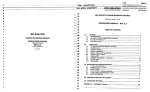
IMPORTANT MANUAL
Do Not Throw Away
Operator's
Manual
Model No.
358.797922-32cc
358.797950-22cc
358.797982-32cc
358.797961-22cc
358.797990-32cc
Always
Wear Eye Protection
. CRAFTSMAN®
Hours (CST)
Mon + Sat 7 a.m+- 7 p.m.
Sun !0 a.m. - 7 p.m.
_
READ THE OPERATOR'S
DANGER
MANUAL AND FOLLOW
ALL WARNINGS AND
SAFETY INSTRUCTIONS.
FAILURE TO DO SO CAN
RESULT IN "SERIOUS
INJURY.
22cc132cc
2-CYCLE
ENGINE
155/170 Air Velocity
GASOLINE
BLOWER
• Assembly
• Operation
• Customer Responsibilities
• Service Adjustments
• Repair Parts
° Table of Contents - Inside Back Cover
Sears, Roebuck and Co., Hoffman Estates, IL 60179 U.S.A.
530-083059-07/05t94
© t994, Sears, Roebuck and Co.
i
SAFETY RULES
CAUTION: ALWAYS DISCONNECT SPARK PLUG WIRE AND PLACE WIRE WHERE tT CANNOT I
CONTACT
SPARK PLUG TO PREVENT ACCIDENTAL
STARTING
WHEN SETTING
UP.t
TRANSPORTING,
ADJUSTING OR MAKING REPAIRS.
1
OPERATOR
SAFETY
•
Always wear eye protection to prevent rocks or debris
from being blown or ricocheting into eyes and face which
can result in blindness and!or other serious injury.
• Always wear a respirator or facemask when working
with the unit in dusty' environments.
• Always wear heavy, long pants, boots, and gloves (To
avoid shock of static electricity, do not wear rubber
gloves). Do not go barefoot or wear short pants, sandais, jewelry, loose clothing, or clothing with loosely
hanging straps, ties, tassels, etc.; they can be caught in
moving parts. Secure hair so it is above shoulder
length.
• Do not operate this unit when you are tired, ill, or under
the influence of alcohol, drugs, or medication.
• Keep children, bystanders, and animals away from the
work area at a minimum of 30 feet when starting or
operating the unit.
. Inspect the area before starting the unit. Remove all
debris and hard objects such as rocks, glass, wire, etc.
that can ricochet, be thrown, or otherwise cause injury
or damage during operation.
•
°
•
•
•
•
,
UNIT/MAINTENANCE
SAFETY
• Have all maintenance other than the recommended
procedures described in the Operator's Manual performed by your Sears Service Center.
° Disconnect spark plug before performing maintenance
except for carburetor adjustment.
• Use only genuine replacement parts as recommended
by Sears to avoid creating a hazard and/or voiding your
warranty.
• Check air intake openings, blower tubes, elbow tube,
and vacuum tubes frequently, always with the engine
stopped. Keep vents and tubes free of debris which can
accumulate and restrict proper air flow.
• Do not use an accessory andlor attachment other than
those recommended by Sears with your unit.
•
•
°
FUEL SAFETY
•
•
•
•
Mix and pour fuel outdoors.
Keep away from sparks or flames.
Use a container approved for fuel.
Do not smoke or allow smoking near fuel or the unit or
while using the unit.
• Wipe up all fuel spills before starting engine.
, Move at least t0 feet (3 meters) away from fueling site
before starting engine.
• Stop engine and allow unit to cool before removing fuel
cap.
OPERATION
SAFETY
•
•
no longer turning to avoid serious injury from the rotating blades.
Inspect the entire unit before each use for worn, loose,
missing, or damaged parts. Do not use untit the unit is
in proper working order.
Keep the outside surfaces free of oil and fuel.
Never start or run unit inside a closed room or building.
Breathing exhaust fumes can kill.
Never use for spreading chemicals, fertilizers, or any
other material which may contain toxic substances.
Do not set the unit on any surface except a clean, hard
area to start the engine or while the engine is running.
Debris such as gravel, sand, dust, grass, etc. could be
picked up by the air intake and thrown out through the
discharge opening, damaging the unit, property, or
causing serious injury to bystanders or the operator.
Avoid dangerous environments. Do not use in unventilated areas or where explosive vapors or carbon
monoxide build up could be present.
Avoid situations which could set the vacuum bag on
fire. Do not vacuum discarded cigars or cigarettes or
ash from fireplaces, barbecue pits, brush piles, etc. To
avoid spreading fire, do not use blower near leaf or
brush fires, fireplaces, barbecue pits, ashtrays, etc.
Do not overreach or use from unstable surfaces such
as ladders, trees, steep slopes, rooftops, etc. Use extra
care when cleaning on stairways. Keep firm footing and
balance at all times.
Never place objects inside the blower tubes; always
direct the blowing debris away from people, animals,
glass, and solid objects such as trees, automobiles,
walls, etc. The force of air can cause rocks, dirt, or
sticks to be thrown or to ricochet which can hurt people
or animals, break glass, or cause other damage. Do not
allow the unit to be used as a toy.
Never place any object in the air intake opening as this
could restrict proper air flow and cause damage to the
unit.
Never run unit without the proper equipment attached.
When used as a blower, always install a blower tube.
When used as a vacuum, always install vacuum tubes
and vacuum bag assembly.
Use only for jobs explained in this manual.
TRANSPORTING
•
•
•
-
Stop the engine before opening the vacuum inlet door
or attempting to insert or remove the vacuum tubes.
The engine must be stopped and the impeller blades
•
AND STORAGE
Stop the unit before transporting.
Allow the engine to cool, and secure the unit before
storing or transporting in a vehicle.
Empty the fuel tank before storing or transporting the
unit. Use up any fuel left in the carburetor by starting
the engine and letting the engine run until it stops.
Store unit and fuel in an area where fuel vapors cannot
reach sparks or open flames from water heaters, electric motors or switches, furnaces, etc.
Store the unit out of the reach of children.
SAFETY NOTICE
Exposure to vibrationsthrough prolonged use of gasoline powered hand units could cause blood vessel or nerve damage in the
fingers, hands, and wrists of people prone to circulation disorders or abnormal swellings. Prolonged use in cold weather has been
linked to blood vessel damage in otherwise healthy people, tf symptoms occur such as numbness, pain, loss of strength, change
in skin color or texture, or loss of feeling in the fingers, hands or wrists, discontinue the use of this unit and seek medical attention. An anti-vibration system does not guarantee the avoidance of these problems. Users who operate power tools on a continuaJ and regular basis must monitor closeJy their physical condition and the condition of this unit.
I
,,
dl3k
IT
MEANS
ATTENTION!!!
BECOME
ALERT!!]
YOUR SAFETY
INVOLVED.
LOOK
FOR--THIS
SYMBOL TO
POINT OUT
IMPORTANT
SAFETY ISPRECAUTIONS.
-2-
SAFETY
RULES
WARNING
THIS POWER UNIT CAN BE DANGEROUS!
THIS UNIT CAN CAUSE SERIOUS INJURY OR
BLINDNESS
TO THE OPERATOR
AND OTHERS.
THE WARNINGS
AND SAFETY
INSTRUCTIONS
IN THIS MANUAL MUST BE FOLLOWED TO PROVIDE REASONABLE
SAFETY AND EFFICIENCY IN USING THIS UNIT. THE OPERATOR IS RESPONSIBLE
FOR
FOLLOWING THE WARNINGS AND INSTRUCTIONS
IN THIS MANUAL AND ON THE UNIT.
READ THE ENTIRE OPERATOR'S
MANUAL BEFORE ASSEMBLING
AND USING THIS
UNIT! RESTRICT THE USE OF THE POWER UNIT TO PERSONS WHO READ, UNDERSTAND AND FOLLOW THE WARNINGS AND INSTRUCTIONS
IN THIS MANUAL AND ON
THE UNIT.
THIS UNIT IS DESIGNED FOR BLOWER
AND VACUUM USE ONLY. NEVER USE
ANY OTHER ATTACHMENTS WiTH THIS
UNIT EXCEPT THE OPTIONAL GUTTER
ATTACHMENT.
BLOWER CAN THROW OBJECTS VIOLENTLY. YOU CAN BE BLINDED OR
INJURED. WEAR EYE AND LEG PROTECTION.
THROWN_r
OBJECTS
FACE
SHIELD
THIS IS THE HAZARD ZONE FOR BLOWN
OBJECTS.
BLOWER
CAN
THROW
OBJECTS VIOLENTLY. OTHERS CAN BE
BLINDED OR INJURED. KEEP PEOPLE AND
ANIMALS 30 FEET (10 METERS) AWAY.
30 FOOT
(10 METERS)
HAZARD ZONE
READ OPERATOR'S MANUAL. FOLLOW
ALL WARNINGS AND INSTRUCTIONS.
FAILURE TO DO SO CAN RESULT IN
SERIOUS INJURY.
OPERATOR'S
MANUAL
_3-
I
CONGRATULATIONS
on yourpurchaseof a Sears
Craftsman
Gasoline
Blower.It hasbeendesigned,
engineeredandmanufactured
to giveyouthebestpossible
dependability
andperformance.
Should you experience any problems you cannot easily
remedy,
please contact your nearest Sears Service
Center/Department
or Call the 1-800 number listed on
the front of this manual. Sears has competent,
well
trained technicians
and the proper tools to service or
repair this unit.
Please read and retain this manual, The instructions will
enable you to assemble and maintain your unit properly.
Always observe the "SAFETY RULES."
MODEL NUMBERS:
PRODUCT
SPECIFICATIONS
AIR VELOCITY
358.797950/358.797961 ...155mph
358.797922/358.797982
358.797990 ....................... 170mph
AIR VOLUME
358.7979501358.797961 ...350 cu. ftJmin.
358.797922/358.797982
358.797990 ....................... 360 cu. ftJmin.
ENGINE
358,797950/358.797961 ..22cc 2-cycle AIR-COOLED
358.797922/358.797982
358.797990 ...................... 32cc 2-cycle AIR-COOLED
ENGINE RPM
Od_eerating
.......................... 7000-7600
..................................... 3800-4600
FUEL/OIL MIX RATIO ....... 40:t (3.2oz. per gallon
gasl
358.797922
358.797950
358.797982
358.797961
358.797990
IGNITION .............................. Solid State
(air gap .010" to .014")
IGNITION TIMING ................ Non-adjustable, Fixed
SPARK PLUG ...................... Champion (CJ*8Y)
SPARK PLUG GAP ............. 025"
SERIAL NUMBER:
DATE OF PURCHASE:
SPECIAL NOTICE
For users on U.S. Forest Land and in some states, including
California (Public Resources Codes 4442 and 4443), Idaho,
Maine, Minnesota, New Jersey, Oregon, and Washington:
Certain internal combustion engines operated on forest,
brush, and/or grass-covered lands in the above areas are
required to be equipped with a spark arrestor, maintained in
effective working order, or the engine must be constructed,
equipped, and maintained for the prevention of fire. Check
with your state or local authorities for regulations pertaining
to these requirements. Failure to follow these requirements
is a violation of the law. This unit is not factory-equipped with
a spark arrestor; however, a spark arrestor is available as an
optional part. If a spark arrestor is required in your area, contact your SEARS Service Center/Department for the correct
kit.
THE MODEL AND SERIAL NUMBER WILL BE FOUND
ON THE PRODUCT.
YOU SHOULD RECORD BOTH SERIAL NUMBER
AND DATE OF PURCHASE AND KEEP IN A SAFE
PLACE FOR FUTURE REFERENCE.
MAINTENANCE
AGREEMENT
A Sears Maintenance Agreement is available on this
product. Contact your nearest Sears Store for details.
CUSTOMER
RESPONSIBILITIES
• Read and observe the safety rules.
• Followa regularschedule in maintaining, caring for, and
using your unit.
• Follow the instructions under "Customer Responsibilities" and "Storage" sections of this Operator's Manual,
MANUFACTURED
UNDER ONE OR MORE OF THE FOLLOWING U.S. PATIENTS:
5,269,665; 5,035,5B5;
4,674.146;
4,940,028;
RE 33,050; 4,798.185;
4,402,106;
D3:22,971. OTHER U.S. AND FOREIGN PATENTS PENDING,
FULL ONE YEAR WARRANTY ON SEARS BEST GAS BLC)WER MODEL 358.797950 & 358.797961
Foroneyearfromthedateofpurchase,
whenthisGasBlower
ismaintained,
lubricated
andtuned-up
according
totheinstructions
intheowner's
manual,
Searswillrepair,
freeofcharge,
anydefectinmaterial
orworkmanship.
Thiswarranty
excludes
theblower
tubes,
spark
plug,andaircleaner,
which
areexpendable
partsandbecomewornduring
normaluse.
If thisBlower
isusedforcommercial
purposes,
thiswarranty
applies
for90daysfromthedateofpurchase.
If thisBlower
isusedforrental
purposes,
this
warranty
applies
for30daysfromthedateofpurchase.
Thiswarranty
applies
onlywhilethisproduct
is inuseintheUnitedStates.
WARRANTY
SERVICE
ISAVAILABLE
BYRETURNING
THEBLOWER
TOTHENEAREST
SEARSSERVICE
CENTERINTHEUNITEDSTATES.
Thiswarranty
gives
youspecific
legalrights,
andyoumayalsohaveother
rights
which
varyfromstatetostate.
SEARS,ROEBUCKANDCO. DEPT.817WA HOFFMANESTATES,IL 60179
FULL TWOYEAR WARRANTYONSEARSBESTGAS BLOWERMODEL358.797922,358.797982& 358.797990
Fortwoyearslromthedateofpurchdse,
whenthisGasBlower
ismaintained,
lubricated
andtuned-up
according
totheinstructions
intheowner's
manual,
Searswillrepair,
freeofcharge,
anydefectinmaterial
orworkmanship.
Thiswarranty
excludes
theblower
tu_s,sparkplug,
andaircleaner,
which
areexpendable
partsandbecomewornduring
normal
use.
If thisBlowerisusedforcommercial
purposes,
thiswarranly
appliesfor90daysfromthedateofpurchase,
ifthisBlowerisusedforrental
purposes,
this
warranty
applies
for30daysfromthedateofpurchase.
Thiswarranty
appliesonlywhile
thisproduct
isinuseintheUnitedStates.
WARRANTY
SERVICE
ISAVNLABLE
BYRETURNING
THEBLOWER
TOTHENEAREST
SEARSSERVICE
CENTERtNTHEUNITEDSTATES.
Thiswarranty
givesyouspecificlegalrights,
andyoumayalsohaveother
rightswhich
varyfromstateto state.
SEARS,ROEBUCKANDCO. DEPT.817WA HOFFMANESTATES,IL 60179
o
-4-
HARDWARE
_._
I....
i illiiiiii
ii
iiiiii
iiii
..........
i
II
II
II
IIIIII
IIIIII I II I
CONTENTS
I
nil
lli
I
Illll
IIIIIIIIIIllLl IIJlll
I
7
IIIII
iiii
I
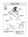
Parts packed separately in carton
VACUUM BAG
358.797982, 358.797950
& 358.797990
OPERATOR'S
MANUAL
UPPER VACUUM TUBE
358.797982, 358.797950
& 358.797990
LOWER VACUUM TUBE
358.797982,
358.797950
& 358.797990
2-CYCLE ENGINE OIL
ELBOW TUBE
358.797982,
358.797950
& 358.797990
ASSIST HANDLE
358.797982,
358.797950
& 358.797990
CONCENTRATOR
NOZZLE
358.797950
& 358,797961
ONLY
FLARE NOZZLE
358.797982J358_797990
ONLY
f
BLOWER TUBE
TO REMOVE BLOWER FROM
CARTON
TOOLS REQUIRED FOR ASSEMBLY
• Standard Screwdriver
• Remove loose parts included with Blower.
• Remove all packing material.
• Check carton thoroughly for additional loose parts.
-5-
iiN
,,,,,,,,,
,,,,,,,,,, ,,,,,, ,,,
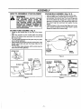
HOW TO ASSEMBLE
YOUR
................................................
BLOWER
VACUUM BAG ASSEMBLY
(Fig 2 & 3)
• Open the zipper on the large end of the vacuum bag.
• Insert the elbow tube, grooved end first, through the zipper opening in the vacuum bag. Then, push the grooved
end of the elbow tube through the vacuum bag tube
opening in the other end of the vacuum bag. Make sure
the vacuum bag tube opening is flush against the tube
flange.
• Close the zipper on the vacuum bag. Make sure the zipper is closed completely and the zipper seam is tucked
toward the inside of the vacuum bag.
WARNING
STOP THE ENGINE BEFORE OPENING
THE
VACUUM
iNLET
DOOR
OR
ATTEMPTING TO INSERT OR REMOVE
THE VACUUM TUBES. THE ENGINE
MUST BE STOPPED AND THE IMPELLER
BLADES NO LONGER TURNING TO
AVOID SERIOUS INJURY FROM THE
ROTATING BLADES
pLOWER TUBE ASSEMBLY (Fig 1)
•
•
•
•
Locate the two locking tabs on the side of the blower
tube.
Align the grooves on the nozzle with the locking
tabs on the blower tube and push the nozzle onto
the blower tube
Turn the nozzle clockwise until the parts snap into place
and are firmlytightened.
Align grooves on the blower tube with locking tabs in the
blower outlet (inset) and push the blower tube into the
blower outlet.
Turn the blower tube clockwise until the parts snap into
place and are firmly tightened.
ELBOW TUBE
v_uu_i
BAG TUBE
OPENING
LOCKING TABS
ZIPPER
OPENING
Figure 2
BLOWER
OUTLET
RECESSED
GROOVES
VACUUM BAG
TUBE OPENING
BLOWER TUBE
FLARE NOZZLE
LOCKING TABS
TUBE FLANGE
GROOVES
Figure 1
Figure 3
-6-
WRONG
ASSEMBLY
VACUUM
TUBE
ASSEMBLY
LOCKING
TABS
(Fig 4, 5, 6, & 7)
• Remove the blower tube from the engine.Page 6.
• Set the unit, bloweroutletup, on a flat surface.Open the
vacuum inlet cover as follows:
- Insert a screwdriverintolatch area.
- Gently twist the tip of the screwdriverand open the
vacuum intet cover with your otherhand.
, Holdopen vacuuminletcoverand alignthe grooveson the
uppervacuumtubewiththe lockingtabsinsidethe vacuum
inlet. Insertthe uppervacuumtube and turnclockwiseuntil
partssnaptogether.
• Assemble the vacuum tubes by aligning the slanted end
of the lower vacuum tube with the blower outlet as
shown. Push the two tubes together until they are snug.
NOTE; The bottom end of the lower vacuum tube is cut at
an angle. Make sure slanted end of vacuum tube is
aligned with blower outlet.
• To attach the vacuum bag, align the grooves on the
elbow tube with the locking tabs inside the blower outlet. Be sure to atign the dot on the elbow tube with the
dot on the blower housing, insert elbow tube into blower outlet; twist elbow tube counterclockwise until parts
snap together,
• Adjust the vacuum bag at the elbow tube to remove any
twists.
ELBOW TUBE
TO THE
RIGHT
GROOVE
Figure 6
VACUUM BAG!
(
LATCH AREA
Figure 7
BLOWER OUTLET
SHOULDER
VACUUM
INLET COVER
Figure 4
LOCKING TAB
SLANTED
END
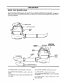
STRAP ADJUSTMENT
(Fig 7)
• With your left hand hold the unit in an upright position,
supporting the lower vacuum tube on the ground.
Make sure the blower outlet and vacuum bag are
positioned on your right-hand side.
• Place vacuum bag strap around your back and over
your Ieft shoulder. Snap vacuum bag hook onto the
strap retainer in the top handle.
• Extend your right arm toward the rear of the vacuum
bag,
• Adjust the shoulder strap until the vacuum bag/shoulder
strap seam lies between your thumb and index finger.
• Make sure the shoulder strap is adjusted to allow a
free flow of air from the elbow tube. If the vacuum bag
is kinked, the unit will not operate properly.
AREA
BLOWER CONVERSION
UPPER VACUUM
TUBE
• Stop the engine. Allow the engine to cool.
- Remove the vacuum tubes and vacuum bag assembly,
- Secure the vacuum inlet cover. Make sure that the
latch on the vacuum inlet cover is securely fastened.
• Reinstall the blower tubes as shown in the "Blower
Tube Assembly" section.
VACUUM INLET
LOWER.VACUUM
TUBE
VACUUM INLET COVER
CHECK LIST
• Check all fasteners. Make sure they are tight and there
are no loose parts.
Figure 5
-7-
OPERATION
KNOW YOUR BLOWER (Fig 8)
READ THIS OPERATOR'S MANUAL AND SAFETY RULES BEFORE OPERATING YOUR BLOWER. Compare the
illustrations with your unit to familiarize yourself with the location of the various controls and adjustments. Save this manual for future reference.
LOCK
:FLER
& GUARD
PLUG
THROTTLE
TRIGGER
STOP
SWITCH
CHOKE
LEVER
ASSIST HANDLE
ON SOME MODF.LS
(See Hardware Chart)
/
BLOWER
TUBE
FLARE NOZZLE
_
CONCENTRATOR NOZZLE
Figure 8
The CHOKE LEVER is used for starting a cold engine.
The THROTTLE TRIGGER controls engine speed.
The STARTER ROPE HANDLE is used for starting the
engine.
The STOP SWITCH is used to stop the engine.
The CONCENTRATOR
the flow of air.
The THROTTLE LOCK is used to hold the throttle in the
run position.
NOZZLE is used to concentrate
The FLARE NOZZLE is used to disperse the air flow
over a wider area.
-8-
IIIIIIIIIIII
III
Jl
ILl
IIII
I
.....................................................................
111111
OPERATION
llll
iiii
II
LU
II
III
I[
i
-
......................................................................................
,,,,,,,,,,,,,,,,,,,,
,,,
...............
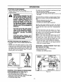
BLOWER SAFETY
WARNING:
THE BLOWER CAUSES OBJECTS TO BE THROWN
VIOLENTLY. THE OPERATOR MUST WEAR A SAFETY
FACE SHIELD OR GOGGLES. ALWAYS WEAR HEAVY,
LONG PANTS AND BOOTS. KEEPOTHERSAT LEAST 30
FEET (10 METERS)AWAY.
THIS UNIT WILL THROW OBJECTS.KEEPOTHERS INCLUDING
CHILDREN, ANIMALS,BYSTANDERSAND HELPERSAT LEAST
30 FEET (10 METERS)AWAY FROMTHE OPERATORAND UNIT.
STOP THE ENGINE IF YOU ARE APPROACHED. IN AREAS
WHEREOTHER PEOPLE AND ANIMALSARE PRESENT, SUCH
AS
NEAR SIDEWALKS,
STREETS,
HOUSES,
ETC.,/T.!S
STRONGLY
RECOMMENDEDTHAT
THE
OPERATOR
UsE ira:
FACE
SHIELD
/
_100F_OETTERs)
\
BUDDY SYSTEM;,TI_ATIS, HAVE ANOTHER PERSON SERVE
HAZARDZONE /
/"
\
ASA LOOK-OUT, KEEPINGHIMSELFANDOTHERS AT LEAST
_'_
!11'
•
30FEET (10METERS) AWAY FROMTHE OPERATOR.
f[
"1" _
I_...,,.._J. , ]
DO NOT ASSEMBLE OR DISASSEMBLE THE VACUUM TUBE
I _ __
_
41qqJ
WHILE THE ENGINE IS RUNNING. INSERTING OR REMOVING
4!1\_
30 FT _
/_.
THE VACUUM TUBE WHILE THE ENGINE IS RUNNING CAN
"" \,,,.
,_1',; _
_
Y
RESULT IN SERIOUS INJURY. ALWAYS STOP THE ENGINE
_
J'4kt
AND DISCONNECT THE SPARK PLUG BEFORE UNCLOGGING
THE UNIT OR PERFORMING ANY MAINTENANCE ON THE
USE ONLY GOODQUALITY
VACUUM BAG.
REPLACEMENTPARTS
OPERATOR SAFETY (Fig 9 & 10)
attached. When using your unit as a blower always
install blower tubes. When using your unit as a vacuum, always install vacuum tubes and vacuum bag
assembly. Make sure vacuum bag assembly is completely zipped.
, When using the unit as a vacuum, always use the
shoulder strap to avoid loss of control.
, Use only good quality accessories or attachments.
• Read your Operator's Manual. Make sure you completely understand and can follow all warnings and
safety instruction in the manual before operating.
• Always wear a respirator or facemask when working in
dusty environments.
• Always wear eye protection to prevent rocks or debris
from being blown or ricocheting into eyes and face
which can result in blindness or other serious injury.
• Always wear heavy, long pants, boots, and gloves. (To
avoid shock of static electricity, do not wear rubber
gloves). Do not go barefoot or wear short pants, sandais, jewelry, loose clothing, or clothing with loosely
hanging straps, ties, tassels, etc. Secure hair so it is
above shoulder length.
BLOWER/VACUUM
SAFETY
• As a blower, the unit is designed to sweep debris,
grass, straw, leaves, small twigs, or light snow. It can
also be used for fast drying wet outdoor areas such as
a patio, sidewalk, carport, etc. Never use for spreading
or misting chemicals, fertilizers, or any other materials
which may contain toxic substances.
• As a vacuum, the unit is designed to pick up dry material such as leaves, grass, small twigs, and bits of
paper. Do not attempt to vacuum stones, gravel,
metal, broken glass, or any other debris which may
cause damage to the impeller. Do not attempt to vacuum water or any other liquids. Vacuuming water or
other liquids wilt cause damage to the engine. Avoid
situations that could catch the vacuum bag on fire. Do
not operate near an open flame. Do not vacuum discarded cigars or cigarettes or ash from fireplaces, barbecue pits, brush piles, etc.
• Inspect area before starting engine. Remove al[ debris
and objects such as rocks, glass, wire, large sticks,
etc., that _;ancause damage during operation.
- Use the correct operating position. Do not overreach
or use from unstable surfaces such as ladders, trees,
steep slopes, roof tops, etc. Keep firm footing and balance at all times.
UNIT SAFETY
• Inspect the entire unitbefore each use. Replace damaged parts. Check for fuel leaks and make sure all fasteners are in place and securely fastened.
• Check air intake opening, blower tubes, vacuum tubes,
and elbow tube frequently, always with engine stopped
and spark plug disconnected. Keep vents and discharge tubes free of debris which can accumulate and
restrict proper air flow.
- Never place objects inside blower tubes; always direct
blowing debris away from people, animals, glass, and
solid objects such as trees, automobiles, walls, etc.
The force of air can cause rocks, dirt, or sticks to be
thrown or to ricochet which may hurt people or animals, break glass, etc.
• Never run the unit without the proper equipment
-9-
I.._
........................................
,llllll,
ii i i i ii ii ii i
ii
i
illlll i
i
OPERATION
• iii
OPERATING / USE TIPS
ASSISTHANDLE
USE
%
,lllll,llL i
OPERATING
1,op
HANDLE_
ASSISTHANDLE
MODEL: 358.797982_
& 358.797950
BLOWER
_
_
TIPS --
BLOWER
• Always work going away from solid objects such as
walls, trees, automobiles, and fences.
• Clean corners by starting in corners and moving outward to flat areas to prevent an accumulation of debris
which could fly into face.
• Be careful when working near plants. The force of the
air could damage tender plants.
• Direct air flow by directing the nozzle down or to one
side.
• Vary the air flow by adjusting your grip on the throttle
trigger.
• While using the models 358.797982 and 358.797950,
use the assist handle located on the back of the unit
when working above the waist or when a two-handed
grip is desired.
• Uses For Your Blower:
- Sweeping debris or grass clippings from driveways,
sidewalks, patios, parks, parking lots, barns, stadiums, etc.
- Blowing grass clippings, straw, or leaves into piles.
- Fast drying wet outdoor areas such as a patio.
- Removing debris from corners, around joints, and
between bricks.
- Blowing light snow from driveways, sidewalks, or
patios.
_PERATION
Figure 9
EYE
ASSIST HANDLE
MODEL: 358.797982
& 358.797950
HANDLE
OPERATING
TIPS -- VACUUM
• When using your unit as a vacuum, best results are
achieved when the unit is operated at full throttle.
Engage the throttle lock before beginning vacuuming
procedures.
o Move the unit slowly back and forth over debris to be
vacuumed. Avoid forcing the vacuum tube into a pile of
debris as this can clog the unit.
• The vacuum can pick up objects that are too big to
pass through the impeller. This type of object will fall
out of the vacuum tubes when the engine is stopped.
° If the unit becomes clogged:
- Stop the engine and disconnect the spark plug wire.
Do not attempt to remove obstructions with the
engine running.
- Wait until the impeller has completely stopped turning, then remove the vacuum tube.
- Carefully reach into the vacuum opening and clear
out debris.
• The vacuum bag must be property emptied and maintained to avoid deterioration and obstruction of air flow
which will reduce the performance of the vacuum.
- Empty the vacuum bag after each use.
- Remove the vacuum bag/elbow from the unit by
turning it in a clockwise direction. Do not store vacuum bag containing leaves, grass, etc.
- Wash the vacuum bag once a year as follows:
Turn the vacuum bag inside out.
Hang it up.
Thoroughly hose it down.
Let vacuum bag hang until dry.
VACUUM
OPERATION
Figure 10
WARNING
DO NOT USE THE UNIT AS A BLOWER
WITHOUT THE BLOWER TUBES PROPERLY ATTACHED TO AVOID FLYING
DEBRIS AND/OR IMPELLER CONTACT
WHICH CAN CAUSE SERIOUS INJURY,
ALWAYS WEAR EYE PROTECTION TO
PREVENT ROCKS OR DEBRIS FROM
BEING BLOWN OR RICOCHETING INTO
THE EYES AND FACE WHICH CAN
RESULT IN BLINDNESS OR SERIOUS
INJURY.
DO NOT USE THE UNIT AS A VACUUM
WITHOUT THE VACUUM TUBE AND
VACUUM BAG PROPERLY ATTACHED
TO AVOID FLYING DEBRIS AND/OR
IMPELLER
CONTACT
WHICH
CAN
CAUSE SERIOUS INJURY. ALWAYS
MAKE SURE THE VACUUM BAG IS COMPLETELY ZIPPED BEFORE THE ENGINE
IS STARTED.
-10-
IL
OPERATION
,,, ,,,, ,,
BEFORE
STARTING
..............................................
ENGINE:
2-CYCLE
ii.
AIR-COOLED
ENGINE
i i
OIL
WARNING:
BE SURE TO READ THE FUEL SAFETY
INFORMATION IN THE SAFETY RULES
SECTION ON PAGE 2 OF THIS MANUAL
BEFORE YOU BEGIN.
"CRAFTSMAN 40:1 2-cycle AIR-COOLED engine oil is
strongly recommended. This oil is specially blended with
fuel stabilizers for increased fuel stability (extends fuef
life up to 5 times longer) and reduced smoke.
IF YOU DO NOT UNDERSTAND THE FUEL
SAFETY SECTION DO NOT ATTEMPT TO
FUEL YOUR UNIT; SEEK HELP FROM
SOMEONE THAT DOES UNDERSTAND
THE FUEL SAFETY SECTION OR CALL
THE CUSTOMER ASSISTANCE HOTLINE
AT 1-800-235-5878.
If CRAFTSMAN 40:1 2-cycle AIR-COOLED engine oil is
not available, use a good quality 2-cycle AIR-COOLED
engine oil that has a recommended fuel mix of 40:1.
IMPORTANT! Do not use:
• AUTOMOTIVE OIL
• BOAT OILS (NMMA, BIA, etc.)
GASOLINE
The two-cycle engine on this product requires a fuef
mixture of regular unleaded gasoline and a high quality
40:1 2-cycle AIR-COOLED engine oil for lubrication of
the bearings and other moving parts, The correct fuel/oil
mixture is 40:t (see Fuel Mixture Chart). Too little oil or
the incorrect oil type witl cause poor performance and
may cause the engine to overheat and seize.
Gasoline and oil must be premixed in a clean approved
fuel container. Always use fresh regular unleaded gasoline.
The engine has been certified
to operateon unleaded
gasoline and CRAFTSMAN 40:1 2-cycle AIR-COOLED
engine oil.
IMPORTANT: Experience indicates that alcohol blended
fuels called gasohol (or using ethanol or methanol) can
attract moisture,which leads to oil/gasseparationand formation of acids during storage.Acidicgas can damage the
fuel system of an engine while in storage. To avoidengine
problems, the fuel system should be emptied before storage for 30 days or longer. Drain the fuet tank, then run the
engine and letting it run until it stops. Use fresh rue! next
season. See STORAGE instructionsfor additionalinformation. Never use engine or carburetor cleaner productsin
the fuel tank or permanentdamage may occur.
These oils do not have proper additives for 2-cycle AIRCOOLED engines and can cause engine damage.
GASOLINE AND OIL MIXTURE
Mix gasoline and oit as follows:
• Consult chart for correct quantities.
• Do not mix gasoline and oil directly in the unit's fuel
tank.
FOR ONE GALLON:
• Pour 3.2 ounces of high quality,40:1 2-cycle AIRCOOLED engine oil into an empty, approved one gallon gasoline container.
• Add one gallon of regutar unleaded gasoline to the
gallon container, then securely replace the cap.
• Shake the container.
• The mixture is now ready for use. Fue! stabilizer can
be added at this time if desired; follow mixing instructions on the label.
FUEL MIXTURE CHART
40:1 Fuel:Oil Mix Ratio
Gasoline
1 gallon
1.25 gallons
2.5 gallons
FUEL STABILIZER
Fuel stabilizer is an acceptable alternative in minimizing
the formation of fuel gum deposits during storage. Add
stabilizer to gasoline in fuel tank or storage container.
Always follow the fuel mix ratio found on the stabilizer
container. Run engine at least 5 minutes after adding stabilizer to allow the stabilizer to reach the carburetor. You
do not have to drain the fuel tank for storage if you are
using fuet stabilizer.
Oil (fl. OZ.)
3.2
4.0
8.0
NOTE:One gallon fuel containers will hold more than one
gallon, tf too much gasoline is in the container, the resulting gas-to-oil fuet mixture wilt not be correct for proper
engine operation.
"CRAFTSMAN
40:1" 2-cycle AIR-COOLED
engine oil is
specially blended with fuel stabilizers. If you do not use
this Sears oit, you can add a fuel stabilizer
(such as
CRAFTSMAN
No. 33500) to your fuet tank.
-11 -
OPERATION
,,,,,,,,
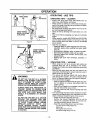
STOPPING
YOUR
,, ,,
,
........................................................
ENGINE
The engine may sound as if it is trying to start before the 5th pufi. If
so, go to the next step i_iately.
• Move the choke lever to the "Half Choke" pos_on.
- Pull the starter rope sharply until the engine runs, but no more
than 6 pulls.
• Move the stop switch to the "Off" position.
• if engine does not stop, move the choke lever to the
full choke position.
WHEN
STARTING THE ENGINE, HOLD THE
DANGER:
UNIT AS SHOWN IN FIGURE 11. DO NOT
SET THE UNIT ON AN"(SURFACE EXCEPT
A CLEAN, HARD AREA WHILE THE
ENGINE IS RUNNING. DEBRIS SUCH AS
GRAVEL, SAND, DUST, GRASS, ETC.
COULD BE PICKED UP BY THE AIR
INTAKE AND THROWN OUT THROUGH
THE DISCHARGE OPENING, DAMAGING
THE UNIT OR PROPERTY OR CAUSING
SERIOUS INJURY TO BYSTANDERS OR
OPERATOR..
If theengine stilthas not started,it isprobablyfkx:x:led.
enginescanbe clearedof excessfuel withthe followingprocedure:
• Movethechokelevertothe '_)ff" position.
- Squeezeand holdthe thrott_ tngger.
° Pull starterrope toclearthe engine of excess fuel.
Starting could require pulling the starter rope handle
many times depending on how badly the unit is flooded.
If engine stilt fails to start, refer to the "Troubleshooting"
Chart.
FOR SAFE STARTING AND OPERATION, FOLLOW ALL SAFETY PRECAUTIONS IN THIS OPERATOR'S MANUAL
AND LABELS ON THE UNIT. DRESS
PROPERLY
BEFORE
STARTING
ENGINE.
Once the engine starts, allow the engine to run 15 seconds, then. move the choke lever to "Off Choke." Allow
the engine to run for 30 more seconds at "Oft Choke"
before releasing the throttle trigger.
NOTE: If the engine dies with choke lever at "Off
Choke" position, move the choke lever to "Half Choke".
Pull starter rope 3 times. Move choke lever to "Off
Choke" position, pull the rope until engine runs. Run
engine 30 seconds with throttle trigger fully squeezed.
• To stop the engine, push and hold the momentary
switch in the "Off" position; do not release until the
engine has completely stopped.
AVOID ANY BODILY CONTACT WITH
THE MUFFLER WHEN STARTING A
WARM ENGINE. A HOT MUFFLER CAN
CAUSE SERIOUS BURNS.
BEFORE STARTING THE ENGINE(Fig. 11)
• Fuel engine. Move 10 feet (3 meters) away from fue!ing site.
• Hold the unit in the starting position as shown. When
using the unit as a blower, make sure the blower end
is directed away from people, animals, glass, and
solid objects. When using the unit as a vacuum, make
sure the vacuum end is directed away from people,
animals, glass, and solid objects..
BLOWER
STARTING
POSITION
STARTING
A WARM ENGINE
NOT RUN OUT OF FUEL
THAT
HAS
° Move choke lever to the "Off Choke" position.
• Squeeze throttle tdgger.
• Pull starter rope until engine starts.
VACUUM
STARTING
POS_ION
THROTTLE
TRIGGE
CHOKE
LEVER
Figure
11
IGNITION SWITCH
STARTING
A COLD ENGINE OR WARM ENGINE
IL
_
.................
Figure 12
AFTER RUNNING OUT OF FUEL (Rg.12)
• Move ignitionswitch to the'On" pos_on.
• Move the choke leverto the "FullChoke"position.
° Squeeze and hold the throttletrigger. Keep the throt/ietrigger
ful_/squeezeduntil the engineruns smooth_.
• Pull starterrope sharply 5 times.
-12_
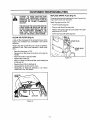
°1
.........
i
ii
i]
i
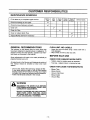
CUSTOMER
,,,,,,,,,,,,,,
.................................
RESPONSIBILITIES
,,,,,,,,,,,,,,,,,,
MAINTENANCE
.................
SCHEDULE
Fill in dates as you complete regular service
Before
Use
After
Use
,,,,,,,
Every
5 Hrs.
Every
10 Hrs.
Every
Season
, ,,i
service Dates
....i,,,
_
,ll,l,!,l
II I III
,,
,, ,,
Check for damage or worn parts
Check for loose fasteners and parts
.............................................................
_'
.
,.
Clean unit
v,'
,,,
;
Clean Air Filter
.......
_ ....
v,'
,,,, ,,
.......
Clean or replace Spark Plug
=j
Inspect Muffler (Service if necessary)
......
,,, ,,,, ,, ,,, L,,,
Ill
I
I
Illll,,llL
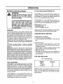
GENERAL RECOMMENDATIONS
CLEAN UNIT AND LABELS
The warranty on this blower does not cover items that
have been subjected to operatorabuse or negligence. To
receive full value from the warranty, operator must maintain blower as instructedin this manual.
- Clean the unit and labels using a damp cloth with a
mild detergent.
• Wipe off the unit with a clean dry cloth.
BEFORE EACH USE
Some adjustments will need to be made periodically to
properly maintain your unit.
All adjustments in the Service and Adjustments section of
this manual should be checked at least once each
season.
CHECK FOR DAMAGED/WORN
PARTS
• Tighten, repair or replace parts as necessary.
• Fuel cap - replace broken or leaking fuel cap.
CHECK FOR LOOSE FASTENERS/PARTS
• Once a year, replace the spark plug, replace air filter.
A new spark plug and clean or new air filter element
assures proper air-fuel mixtureand helps your engine
run better, last longer and reduces harmful emissions.
• Follow maintenance schedule in this manual.
°
•
•
-
Blower Tube
Blower Nozzle
Vacuum Inlet Cover
Blower Outlet
• Vacuum Bag
WARNING
DISCONNECT THE SPARK PLUG BEFORE
PERFORMING MAINTENANCE EXCEPT FOR
CARBURETOR ADJUSTMENTS.
INSPECT THE ENTIRE UNIT. REPLACE DAM-.
AGED PARTS. CHECK FOR FUEL LEAKS
AND MAKE SURE ALL FASTENERS ARE IN
PLACE AND SECURELY FASTENED.
-13-
CUSTOMER
RESPONSIBILITIES
REPLACE SPARK PLUG (Fig 14)
HAZARD AND PRODUCING HARMFUL
CAUTION: TO AVOID CREATING FIRE
EMISSIONS, DO NOT CLEAN FILTER IN
GASOLINE OR OTHER FLAMMABLE
SOLVENT.
The spark plug should be replaced each year to ensure the
engine starts easier and runs better.
Spark Plug gap should be .025".
o Pull off the spark plug boot.
THE HOLES IN THE AIR FILTER MUST BE
FITTED OVER THE POSTS ON THE AIR
FILTER COVER. WHEN INSTALLING THE
AIR FILTERICOVER
BE
SURE THAT THE FILTER DOES NOT
HANG ON THE CHOKE LEVER SCREW,
• Remove and discard the spark plug.
• Replace with correct spark plug and tighten with spark
plug wrench (10-12 Ib-ft)
• Cover spark plug with spark plug boot.
I
CLEAN
AIR FILTER
(Fig 13)
A dirty air filter decreases the life and performance of the
engine and increases fuel consumption and harmful
emissions.
SPARK PLUG
Always clean after 5 tanks of fuel or 5 hours of operation,
whichever i_ less. Clean more frequently in dusty conditions.
PLUG
BOOT
,
,
Move the choke lever to "Full".
Remove the air filter cover on top of the unit (under the
handle).
• Wash the air filter in soap and water.
• Squeeze the air filter dry.
• Add 4 or 5 drops of oil to the air filter. Avoid soaking the
air filter with oil.
• Squeeze the air filter to distribute oil.
• Reassemble the air filter ontothe cover.
• Reassemble air filter!cover assembly to unit. Return
choke lever to the "Off' position.
AIR RLTER
COVER
AIR FILTER
Figure 13
-14-
Figure 14
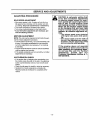
SERVICE
iml
AND ADJUSTMENTS
=ll,llJ
CARBURETOR
ii
i,
i
ill,, ii
..............
i llllll
lll
l i
i,ll
PREPARATION
Tools Required: Small standard screwdriver
• Stop the engine. Make sure your unit is fully assembled with the tubes and nozzle in place.
• Use a fresh fuel mixture with proper gasoline/oil ration
(see Fueling Your Engine section).
• Place the uniton a solid, flat surface free of any loose
-debris.
• Locate the two carburetor adjusting screws. Fig. 15.
• Start the engine and operate for three (3) minutes to
warm up. The engine must be warm for proper adjustments to be made.
• Go to"ADJUSTMENT PROCEDURE."
NOTE; If your unit will not start, proceed to section
"CARBURETOR PRESETS."
ADJUSTMENTS
Carburetor adjustment is critical and if done improperly can permanently damage the engine as well as
the carburetor. Please read all instructions and consult the Troubleshooting
section of this manual
before beginning this process.
• tf engine does not start, it may be flooded, if in doubt,
read the section on flooded engine in the starting section
of this manual priorto beginning any adjustments.
• Poor engine performance can be a result of other
causes such as dirty air filter, clogged muffler outlets,
dirty spark arrestor screen, etc, See the 'TROUBLE
SHOOTING CHART" before proceeding with carburetor adjustments.
• If you are unsure about adjusting the carburetor or
experience any problem while attempting this process,
please call the 1-800 number listed on the front cover
of this manual for further assistance.
CARBURETOR
PRESETS
(Fig,15)
tf your engine will not start due to suspected improper
carburetor adjustment, the following presets may be
required. If used, it is recommended that all steps within
the adjustment procedure be completed in order to
assure a properly set carburetor. If presets are not needed, proceed to section "IDLE SPEED ADJUSTMENT."
NOTE: Be sure to properly prepare the unit as described
in the "PREPARATION" section below.
The carburetor has been adjusted at the factory for
sea level conditions. Adjustments may become necessary if the unit is used at significantly higher altitude or
if you notice any of the following conditions:
-Engine will not continue to run at idle position. See
"IDLE SPEED ADJUSTMENT"
and "MIXTURE
ADJUSTMENT."
-Engine dies Or hesitates when it should accelerate.
See "ACCELERATION CHECK."
- Loss of power which cannot be corrected by cleaning air filter. See "MIXTURE ADJUSTMENT."
-Engine
will not run. See 'TROUBLE SHOOTING
CHART." Then, if carburetor requires adjustment,
begin with "CARBURETOR PRESETS."
Very small adjustments can affect engine performance.
tt is important to turn the screw a very small amount per
adjustment and test performance before making further
adjustments. Each adjustment should be no more than
the width of the slot in the adjusting screw.
• Turn the mixture screw counterclockwise until it stops.
Do not attempt to adjust the screw beyond the stops
as damage can occur.
• Turn idle speed screw clockwise I/2 turn.
• Start the engine and operate for three (3) minutes to
warm up. Go to "ADJUSTING PROCEDURE."
NOTE: Do not attempt to adjust the mixture screw
beyond the stops as damage can occur.
wARNING
THE IMPELLER WILL BE SPINNING DURING THIS PROCEDURE. WEAR YOUR
PROTECTIVE
EQUIPMENT
AND
OBSERVE ALL SAFETY INSTRUCTIONS.
KEEP OTHERS AWAY WHEN MAKING
CARBURETOR ADJUSTMENTS.
Figure 15
THE MIXTURE SETTING IS A HIGHLY
CRITICAL ADJUSTMENT. IF SET INCORRECTLY, PERMANENT DAMAGE WILL
OCCUR TO THE ENGINE. DO NOT RUN
ENGINE AT FULL THROTTLE FOR PROLONGED PERIODS WHILE MAKING THE
MIXTURE ADJUSTMENT.
-15-
ii
Jl|,,uJJJ1J
............
iiiiiiiiii ii
SERVICE
i ii i
,,,,,,,,/
ADJUSTING
..............
PROCEDURE
,
[_
IDLE SPEED ADJUSTMENT
• Allow warm engine tO idfe. If engine wil[not idle, turn
idle speed screw clockwise until the engine runs without stalling. Stop here if performance is satisfactory.
• Turn screw clockwise to increase engine speed.
• Turn screw counterclockwise to stow engine down.
• If you feel further adjustments are necessary, proceed to following sections.
MIXTURE
H
AND ADJUSTMENTS
ADJUSTMENT
NOTE: The unit must be operated at full throttle throughout the mixture adjustment procedure.
• Turn the mixture screw (Fig. 15) counterclockwise until
it stops, if the engine accelerates and runs smoothly,
no further adjustments are necessary, if not continue
to next step.
• Turn the screw slowly the minimum amount clockwise
until the engine runs smoothly.
• If the engine accelerates and runs smoothly, no further
adjustments are necessary.
i
i1,11 iiii1,1,11
ii
CAUTION;
A carburetor
setting that
is too lean (clockwise
adjusfment
on mixture speed screw for maximum speed) wilt cause engine damage=to any 2-cycle
engine
trom
overheatinqand
lack
of lubrication.
Never set the mixture speed screw
so far clockwise
that .you have high
engine
speed lacking
power to
operate, an effective
approach follOWS.
--Turn mixture speed screw clockwise
until engine loses power while operating,
-Turn mixture speed screw the width of
the slot in the adjusting screw counterclockwise until the engine has power
and runs smoothly while operating.
If the engine
does
not operate
according
to these
instructions
after repeating
the adjusting
steps,
do not use the unit. For further
ssistance,
please
call
our
ustomer
Assistance
Hotline
at 1800-235-5878.
ACCELERATION
CHECK
• if the engine dies or hesitates when accelerating, turn
the mixture screw the width of the slot in the adjusting
screw counterclockwise until you have smooth acceleration.
• Check the idle speed for stability, adjust as necessary.
• Recheck for smooth acceleration and stable idle.
Repeat process as necessary for acceptable performance.
-16-
I I
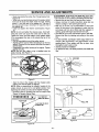
SERVICE AND ADJUSTMENTS
STARTER
ROPE (Fig 16-22)
- Remove the 5 screws from the pulley housing, then
remove the pulley housing and pulley from the engine.
Replace the starter rope if the rope breaks or is badly
worn.
NOTE= When replacing an unbroken rope, cut the rope
and allow the rope to rewind onto the pulley.
REMOVE
SCREWS
WARNING:
DO NOT REMOVE THE PULLEY WHEN
REPLACING
THE STARTER
ROPE.
ALWAYS WEAR EYE PROTECTION
WHEN SERVICING THE STARTER ROPE.
THE
RECOIL
SPRING,
LOCATED
BENEATH THE PULLEY, IS UNDER TENSION. IF THE SPRING POPS OUT, SERI*
OUS INJURY CAN RESULT.
Figure 18
Remove the rope retainer screw from pulley; then,
remove the broken piece of rope, if any.
• Grasp the pulley ratchet and windthe pulley clockwise unlil
the pulley stops. Then, slowly unwind the pulley counterclockwise until the pulley notch is aligned with the pulley
housing notch, then unwind pulleyone complete turn. Insert
the hex wrenchintothe hole formed by the aligned notches.
• Move away from the fue_ tank and melt the ends of the
new rope.
• Allow each melted end to drip once; then while the
rope is still hot, pull each melted end through a clean
rag to obtain a smooth, pointedend.
,
REPAIR OR REPLACE STARTER ROPE
• Disconnect spark plug wire from the spark plug.
• Set unit, blower outlet up, on a fiat surface. Open the
vacuum inlet cover as follows:
- Insert a screwdriver into the latch opening. (Inset).
- Gently twist the screwdriver while opening the vacuum inlet cover with your other hand.
• Remove the impeller nut and washers while holding
the impeller.
LATCH AREA
BLOWER OUTLET
PULLEY
PULLEY RATCHET
\'1
IMPELLER
NUT
PULLEY
VACUUM
INLET COVER
L!
TAB AND SCREW _
R RIB
Figure 16
ROPE RETAINER
HOUSING NOTCH
Remove the 4 impeller shroud screws. Then, remove
the 2 engine shroud screws located by the spark plug.
Remove the impeller shroud from the engine shroud.
IMPELLER
SHROUD
rl _
_
Figure 19
o
Insert one end of the rope through the handle and
secure with a knot. Leave 3/16" pigtail behind the knot.
Insert the other end of the rope through the metal
grommet, then under the rope guide.
IL_
-'_i
_
_'_
SHROUD
____/SCREWS
EN tNE
""-
11" _
SHROUD
<=_'_'_
SCREW'tWASHER
O-RING
_IMPELLER
SHROUD
Figure 17
Figure 20
-17-
SERVICE AND ADJUSTMENTS
,="U,HL,_,
CLEAN/REPLACE
FUEL FILTER (Fig 23 & 24)
• Run fuel tank dry of fuel before proceedingwith this step.
• Remove fuel cap and allow itto hang to side of motor.
• Using a small pair of needle nose pliers, grasp fuel cap
retainer,holdingit in tank openingand pull out.
• With cap out of tank, use a small section of bent wire
similar to that shown in the illustrationto catch fuel line
and slowly pull from tank. When fuet filter appears in
opening,graspwithfingers and removefrom tank.
• Once filter is out of tank, holdfuel line close to fuel filter.
Remove fuel filter by twisting and pulling at the same
time.
• To clean fuel filter, submerge in warm soapy water for 10
minutes. (We recommend a very light mixture of dish
washing liquid.) Then agitate until filter is clean, rinse
thoroughly in warm water, air dry.
, reverseprocessfor installation.
• To replacefuel filter, use same procedure,but installnew
filter.
• Guide rope inside the pulley, then through pulley hole.
Figure 16.
• Wrap rope counterclockwise around the pulley ratchet
and tuck the loose end back under the rope, leaving
about a 1 inch tail next to the retainer rib. The end of
the rope should not go more than 1/4" past the end of
the retainer rib.
• Install and tighten the retainer screw/washer. Figure
16.
NOTE: Do not over tighten the retainer screw. Over tightening the screw can cause the screw post to strip out.
Tighten the screw until the bottom of the washer either
(1) is snug against the rope or (2) contacts the top of the
screw post.
o Pull the rope tightly around the pulley ratchet.
° Slightly pull the rope to relieve the pressure on the hex
wrench. Remove the hex wrench and allow the rope to
rewind slowly.
• Reassemble the pulley housing to the engine. Tighten
screws securely.
NOTE; Be sure the rubber o-ring is installed onto the
pulley housing. See Figure 14.
PULLEY RATCHET
RETAINER
ROPE
RETAINER
SCREW/WASHER
FUEL
ROPE TAIL
CAP
RETAINER
Figure 23
Figure 21
• Align the hole in the impeller with the impeller shaft,
making sure the flat sides are aligned.
NOTE: When re-assembling the impeller housing to the
engine shroud, be sure not to over tighten screws. Over
tightening the screws can strip out the impellerhousing,
• Assemble parts by reversing the first four steps under
"Repair Or Replace Starter Rope'.
UI I I ! I l I 1 l
,, __
,.... , ,,,
I_
1]
_
BENT WIRE !
FLATSlOEOF
IMPELLER SHAFT
SIDE
OF.OLE
',FUEL UNE
.
i
...... '
FUEL
FILTER
/
FIL'rER
"i_
BARREL
NECK
Figure 24
Figure 22
-18-
i
...................................................
•..................
• ..............................
STORAGE
.........
I iii iiiiiiii
iiiiiiiiiiiiiiiiiii
::
i
WARNING:
ALLOW THE ENGINE TO COOL, AND SECURE THE UNIT BEFORE STORING OR
TRANSPORTING IN A VEHICLE.
STORE UNIT AND FUEL IN AN AREA
WHERE FUEL VAPORS CANNOT REACH
SPARKS OR OPEN FLAMES FROM
WATER HEATERS, ELECTRIC MOTORS
OR SWITCHES, FURNACES, ETC.
STORE UNIT WITH ALL GUARDS IN
PLACE. POSITION SO THAT ANY SHARP
OBJECT
CANNOT
ACCIDENTALLY
CAUSE INJURY TO PASSER BY.
STORE THE UNIT OUT OF THE REACH
OF CHILDREN.
GAS BLOWER STORAGE
i
,,
.........................
FUEL SYSTEM
Never use engine or carburetor cleaner products in the
fuel tank or permanent damage may occur to fuel system
components.
Follow these instructions:
1. Drain the fuel from the unit into an approved fue!
container.
2. Drain the fuel lines and carburetor by starting the
engine and letting it run until it stops.
3. Allow the engine to cool before storage.
IMPORTANT: It is important to prevent gum deposits
from forming in essential fuel system parts such as the
carburetor, fuel filter, fuel hose or tank during storage.
Also, experience indicates that alcohol blended fuels,
those that use ethanol or methanol (called gasohol or
oxygenated fuel), can attract moisture and form acidic
gas which will damage your engine. To avoid engine
problems, the fuel system should be emptied before storage of 30 days or longer.
Immediately prepare your unit for storage at the end of
the season or if it will not be used for 30 days or more.
INSTRUCTIONS
If your blower is to be stored for a period of time, clean it
thoroughly prior to storage. Remove any dirt,leaves, oil,
grease, etc. Store in a clean dry area.
• Clean the entire unit.
• Clean air filter Refer to "Customer Responsibilities."
• Lightly oil external metal surfaces to prevent rust from
forming.
• Reassemble all loose parts, being sure that all handles
and guards are in place and are securely fastened.
Replace any damaged parts.
Fuel stabilizer is an acceptable alternative in minimizing
the formation of fuel gum deposits during storage. Add
stabilizer to the gasoline in the fuel tank or fuel storage
container. Always follow the mix instructions found on
stabilizer container. Run engine at least 5 minutes after
adding stabilizer to allow the stabilizer to reach the carburetor.
"CRAFTSMAN 40:1" 2_cycle AIR-COOLED engine oil is
specially blended with fuel stabilizers. If you do not use
this Sears oil, you can add a fuel stabilizer (such as
CRAFTSMAN No. 33500) to your fuel tank.
• Remove spark plug and pour 1 teaspoon of 40:1 oil
through the spark plug opening. Slowly pull the starter
rope 8 to i 0 times to distribute oil to inner engine surfaces.
INTERNAL
ENGINE
° Replace spark plug with a new one of the recommended type and heat range. Refer to "Product
Specifications".
• Clean air filter. Refer to "Customer Responsibilities".
- Reinstall all covers and hardware removed for access;
tighten all screws and fasteners.
• Check entire unit for loose screws, nuts, and bolts.
Replace any damaged, broken, or worn parts.
• Lightly oil external metal surfaces to prevent rust from
forming.
• Use fresh fuel having the proper gasoline to oil ratio at
the beginning of the next season.
OTHER
o Do not store gasoline from one season to another.
* Replace your gasoline can if your can starts to rust.
Rust and/or dirt in your fuel system wilf cause problems.
, Store your unit in a well ventilated area and covered, if
possible, to prevent dust and dirt accumulation. Do not
cover with plastic. Plastic cannot breathe and wilt
induce condensation and eventual rust or corrosion.
IMPORTANT: Never cover unit while engine and exhaust
areas are still warm.
_19-
............
L..J
TROUBLE
, ..........
TROUBLE
SHOOTING
SHOOTING
,, ,,,
iiu
;
,,,,,,,,,,,,,,
,,
.............
,,,,
, .............
CHART
..............................
,,,
,,
,
.............
CHART
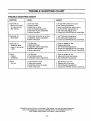
SYMPTOM
CAUSE
REMEDY
Engine willnot
start or will run only
for a few seconds
after starting.
1. Fuel tank empty.
2. Engine flooded.
3. Spark plug not firing.
4. Fuel not reaching carburetor.
5. Carburetor requires adjustment,
6. None of the above.
1. Fill tank with correct fuel mixture.
2. See "Starting Instructions"
3, Install new pluglcheck ignitionswitch.
4. Clean fuel filter; inspect fuel line.
5. See "Carburetor Adjustments."
6. Contact your SEARS Service Center/Dept.
t. Carburetor set too fast or too slow.
2. Carburetor requires adjustment.
3. None of the above.
. See "Carburetor Adjustments."
2. See "Carburetor Adjustments."
3. Contact your SEARS Service Center/Dept.
i ....
,,,,, ,,,,,
Engine will not
idle properly.
,,,,,,, i,
,,,,,,,,L
I
,,
,,,
Engine will not
accelerate, lacks
power, or dies under
a load
1. Air filter dirty.
2. Spark plug fouled.
3, Carburetor requires adjustment.
4. Muffler outlets plugged.
5. None of the above.
1.
2.
3.
4.
5.
Engine
smokes
excessively
Air filter dirty.
Fuel mixture incorrect.
3. Carburetor requiresadjustment.
1. Clean or replace air filter.
2. Refuel with correct fuel mixture,
3. See "Carburetor Adjustments."
.,,,, ,,,,,,,,,, ,jj
Engine
runs hot
1.
.
i i
Clean or replace air filter.
Replace spark plug.
See "Carburetor Adjustments."
Contact your SEARS Service Center/Dept,
Contact your SEARS Service Center/Dept.
,,,J
1. Fuel mixture incorrect.
2. Spark plug incorrect.
3. Carburetor set too low (Lean).
4. None of the above.
,., ,, i
1. See "Fueling Your Unit."
2, Replace with correct plug.
3, See "Carburetor Adjustments."
4. Contact your SEARS Service Center/Dept.
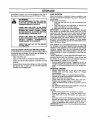
ff situations occur which are not covered in this manual, use care and good judgement.
If you need assistance, contact your SEARS Service Center/Department or the
CUSTOMER ASSISTANCE HOTLINE at 1-800-235-5878
- 20 -
,........................
,,
,,,,,,
,,,,,
.....................
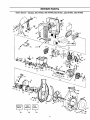
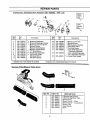
REPAIR
Sears
Blower-
Models
358.797922,
PARTS
358.797950,358.797961,
358.797982,
358.797990
14
32
114
4
12.
40
!
24
I0
!9
112
26
27 _
115
20
10
46
34
33
47
48
49
/59
50
51
52 53
54
55
57
69
65 66
68
74
78
81
93
87
88 89
90
Manual
\
91
92
I
\
I07
108
104
2t
70
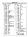
REPAIR
Key
Part
No.
No.
I
2
3
4
5
6
7
8
9
10
11
12
13
530-094712
530-026994
530-029111
530-015635
530-029130
530-015813
530-029072
530-027597
530-015702
530-029117
530-015840
530-024772
530-037140
530-037141
14
530-029067
530-029609
15
16
17
18
19
20
21
22
23
24
25
26
27
28
29
30
31
530-019168
530-069292
530-029129
530-029089
530-015814
530-014121
530-014347
530-014362
530-014160
530-029071
530-029728
530-029112
530-094740
530-069293
530-029116
952-030078
530-015239
530-012244
530-012235
32
33
34
35
36
530-029145
530-039137
530-015776
530-015816
530-019178
530-026413
530-025875
37
38
39
40
41
42
43
44
45
46
47
48
49
50
51
52
53
54
55
56
530-069274
530-069349
530-015162
530-015306
530-029144
530-015849
530-015254
530-015852
530-029114
530-015771
530-037492
530-029115
530-035263
530-019164
530-019165
530-015775
530-029113
530-029070
530-019166
530-027593
530-027594
PARTS
Key
No.
Description
Handle
Front Isolator
Spacer
Screw
Rear Isolator
Screw
Trigger
"Spring
"C" Clip
Throttle Lock Button
Pin
Spring
Shroud- Left Models 358.797961, 797950
Shroud- Left Models 358.797922, 797982, 797990
Shroud-Right
Models 358.797961, 797950
Shroud-Right
Models 358.797922, 797982, 797990
Grommet
Switch
Isolator
Isolator
Screw
Fuel Tank Ass'y. (Incl.
#21, 22 & 106)
Fuel Cap (IncLO'Ring)
Fuel Pick-up Ass'y.
Handle Cover Ass'y.(Incl.
9,10 & 12)
Cover-Air Filter
Models 358.797961,797950
Models 358.797922,797982,797990
AirFilter
AssistHandle -
57
58
59
60
Models 358.797950,797982,797990
Muffler
Spring
Spark Plug
Screw
Cylinder
Models 358.797961,
Models 358.797922,
Part
No.
797950
797982, 797990
Lead Wire
Ignition Module
Screw
Models 358.797961, 797950
Models 358.797922, 797982, 797990
Gasket
Piston Ring
Models 358.797961, 797950
Models 358.797922, 797982, 797990
Piston Kit (Inc!. #36,38, & Pin)
Models 358397961,
797950
Models 358397922, 797982, 797990
Retainer
Screw
Ground Wire
Screw
Wave Washer
Spacer
Choke Shutter
Screw
Cable Assembly
Plate
Carburetor
Gasket
Seal
Screw
Ground Wire
Reed Block
Gasket
Reed Valve
Reed Stop
530-016064
530-014033
530-015126
61
62
63
64
65
66
67
68
69
70
71
72
73
74
75
76
77
78
530-014005
530-010960
530-015788
530-032103
530-015787
530-019158
530-032102
530-015789
530-014016
530-039136
530-347987
530-023817
530-029176
530-014156
530-015823
530-015496
530-027523
530-069486
530-029395
530-069563
79
81
82
83
84
85
86
87
88
89
90
91
92
93
94
95
96
97
530-027569
530-015769
530-032108
530-029110
530-015805
530-019167
530-029182
530-015805
530-027523
530-029119
530-094710
530-029173
530-014157
530-029118
530-015818
530-015441
530-001733
530-014158
98
99
100
101
102
103
104
105
106
107
108
109
110
530-015872
530-094715
530-015667
530-015647
530-015815
530-015672
530-069348
530-069232
530-069247
530-083059
530-069294
530-029404
530-015811
Ill
112
I13
114
530-027525
530-069303
530-029460
115
530-037784
530-037785
530-038554
530-015843
Description
Screw
Crankshaft Ass'y,
Key
ConnectingRod Ass'y.
Models 358.797961,797950
Models 358.797922, 797982, 797990
Spacer
Inner Bearing
Ring
Crankshaft
Seal
Outer Bearing
Retaining Ring
Crankcase
Flywheel
Washer
Spring
Spacer
Crankcase/CrankshaftAssy.
Screw
Screw
Retainer
Starter Pulley (Incl.73)
Starter Spring
Fan Housing Kit
(Incl. Starter Pulley)
Starter Handle
Screw
Bearing
Spacer
Screw
"O" Ring
Eyelet
Screw
Retainer
Roll Pin
Blower Housing (Upper)
Band
Impeller
Hub
Washer
Washer
Nut
Blower Housing (Lower)
(Incl. 99-103)
Screw
Door
Spring
Pin
Screw
Spring
Spark Arrestor Kit
Rope Kit
Line Kit
OperatorsManua!
Gasket Kit
Air Baffle
Washer Models 358.797961, 797950
Spacer - Models 358.797950, 797961
Muffler Guard
Cap - Models 358.797922, 797961
Decal Instruction
Models 358.797922, 797982
Models 358.797950, 797961
Model 358.797990
Screw Models 358.797950, 797982, 797990
NotSho_n
530-061350
530-061933
530-061169
530-061347
530-085152
22
Carton Model
Carton Mode!
Carton Model
Carton Model
Carton Model
358.797922
358.797950
358.797961
358.797982
358.797990
REPAIR
Carburetor
_sembly
Part
Number
PARTS
530-035263
-
_-141
Carb.
Repair
FAt
\
17
1 2
10
8
9 _//
11
Carb.
Gasket
Kit
r
1
\
12
Key
No.
1
2
3
4
5
6
7
I0
ii
Pa_
No.
530-035014
530-035151
530-035016
530-035268
530-035214
530-035217
530-035218
530-035166
530-035164
530-035203
530-0352O8
18
13 14 15
Key
No.
Description
*+ Metering Diaphragm
*+ Metering Diaphragm Gasket
* Metering Lever Pin Screw
Mixture Needle
Mixture Needle Spring
* Mixture Needle Washer
*+ "O" Ring Mixture
*+ Fuel Pump Diaphragm
*+ Fuel Pump Gasket
Idle Speed Screw
Idle Speed Spring
,,,,,,,1,,,1, ,1
* Indicates Carb. Kwik Repair Kit contents
,,,,,,,
,,
,
Part
No.
12
13
14
15
16
17
530-035028
530-035031
530-035188
530-035106
530-035178
530-035264
18
530-035219
19
530-035211
Tube_lower
Tube
* Metering Lever Pin
* Metering Lever
* Metering Lever Spring
* Inlet Needle Valve
* Fuel Inlet Screen
Carb. Kwik Repair Kit
(*Indicates Contents)
Carb. Gasket!Diaphragm
Kit (+Indicates Contents)
*+ Circuit Plate Gasket
,,,
+ Indicates Carb. Gasket/Diaphragm Kit contents
[1{ I
Vacum
Description
II I IIIIIIIII
I
i
lllllllllllllllll
iiiii
ii
Ass'y.
5
4
6
KEY NO.
1
2
3
4
5
6
7
8
23
PART NO.
....
530-06'9272
530-095117
530-069270
530-094662
530-094968
530-094651
530-094740
530-015814
DESCRIPTION
Collection Bag W/Strap
Collection Bag Elbow Tube
Vacuum Tube
Blower Nozzle- - Flare
Blower Nozzle--Concentrator
Blower Tube
Assist Handle
Screw
NOTES
- 24 -
NOTES
- 25 -
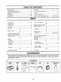
TABLE OF CONTENTS
Safety Rules ......................................................
Product Specifications ........................................
Customer Responsibilities .................................
Warranty ............................................................
Accessories .....................................................
Assembly ...........................................................
LLLIIIIIIIIIIII_III
I
I
/
Jllll
2
4
13
4
26
6
Operation ...........................................................
Service and Adjustments
..................................
15
Storage ............................................................
19
Trouble Shooting
20
..............................................
Repair Parts Ordering/Service
i
I
8
i
ii
im
_:L:
............. Back Cover
:
: :
_::
Llil II
INDEX
................
i
A
.....................................................
26
Adjustments
Carburetor ......................................................
Air Filter ...........................................................
15
14
Accessories
Assembly ...........................................................
B
6
Blower Tube ...............
'........................................
C
6
Carburetor Adjustments ....................................
Customer Responsibilities .................................
15
t3
Spark Plug .......................................................
E
4
Engine
Fuel/Oil ..........................................................
Spark Plug .....................................
11
:.................
4
Starting ..........................................................
Storage ..........................................................
F
t2
!9
Fueling ...........................................................
H
11
Hardware Contents .............................................
I[1
II
5
K
Know Your Blower ..............................................
M
Maintenance Schedule ......................................
Model Number ....................................................
O
8
13
4
Operation ...........................................................
R
8
Repair Parts .......................................................
21
Ordering ...........................................
Back Cover
S
Service and Adjustments ..................................
Specifications
....................................................
Starting ............................................................
Storage ............................................................
T
15
4
12
19
Throttle
Trouble
8
20
Grip ......................................................
Shooting ..............................................
V
Vacuum Bag .............................................
;. ....... 6
Vacuum Tube .....................................................
7
W
Warranty ............................................................
IIIJUII_.H
EIIHIII
Illlll
4
Hllql
HI
ACCESSORIES
iii
i ii
im I.IIIIIHIIII| Hrrfrll.llll iiii fllll.
.11
I
I
These accessories and attachments were available when the unit was originally purchased. They are also available at
most Sears retail outlets and service centers. Most Sears stores can order these items for you when you provide the
model number of your unit.
Accessories
SAFETY
GOGGLES
SPARK
PLUG
GU'N'ER
ATTACHMENT KIT
VACUUM
ATTACHMENT KIT
i,
E i'1
- 26 -
GAS
CAN
AIR
FILTER
SEARS 2-CYCLE
ENGINE OIL
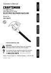
CRAFTSMAN®
Operator's
Manual
22cc/32cc
GASOLINE
ENGINE
BLOWER
Model No.
358.797922-32cc
358.797961-22cc
358.797990-32cc
IF YOU NEED REPAIR
SERVICE
OR PARTS:
REPAIR SERVICE
1-800-4-REPAIR
(1-800-473-7247)
Each Gasoline Blower has its own model number. The model number for your unit wilt be found on a decal attached to the unit.
All parts listed herein may be ordered from any Sears, Roebuck
and Co. Service Centers and most Retail Stores.
WHEN ORDERING REPAIR PARTS, ALWAYS GIVE THE
FOLLOWING INFORMATION AS SHOWN IN THIS LEST:
• PRODUCT-"GASOLINE
• MODEL NUMBER
BLOWER"
- 358.797922
ORDERING
PARTS
1-800-FON-PART
(1-800-366-7278)
358.797950
358.797982
358.797961
358.797990
• PART NUMBER
ASS STANC
• PART DESCRIPTION
Your Sears Merchandise has added vatue when you consider that
Sears has service units nationwide staffed with Sears trained technicians.., professional technicians specifically trained on Sears
products, having the parts, tools and equipment to insure that we
meet our pledge to you, we service what we sell.
Hours (CST)
Mon* Sat 7 a.m. - 7 p.m.
Sun 10 a.m. - 7 p.m.
Sears, Roebuck and Co., Hoffman Estates, tL 60t79 U.S.A.