1
SCCG30 & SCCP30
Service Manual
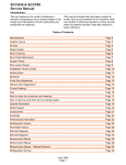
Introduction:
This ice machine is the result of Scotsman’s
decades of experience as an industry leader in the
design and manufacture of both commercial and
residential ice machines.
This manual includes the information needed to
install, start up and maintain the ice machine. Note
any Caution or Warning indicators, as they provide
notice of potential hazards. Keep this manual for
future reference.
Table of Contents
Specifications . . . . . . . . . . . . . . . . . . . . . . . . . . . . . . . . . . . . . . . . . . Page 2
Cabinet Layout . . . . . . . . . . . . . . . . . . . . . . . . . . . . . . . . . . . . . . . . . Page 3
Air flow . . . . . . . . . . . . . . . . . . . . . . . . . . . . . . . . . . . . . . . . . . . . . Page 4
Water Quality . . . . . . . . . . . . . . . . . . . . . . . . . . . . . . . . . . . . . . . . . . Page 5
Door Covering . . . . . . . . . . . . . . . . . . . . . . . . . . . . . . . . . . . . . . . . . . Page 6
Door Panel Attachment . . . . . . . . . . . . . . . . . . . . . . . . . . . . . . . . . . . . . Page 7
Custom Panel . . . . . . . . . . . . . . . . . . . . . . . . . . . . . . . . . . . . . . . . . . Page 8
Door swing change . . . . . . . . . . . . . . . . . . . . . . . . . . . . . . . . . . . . . . . Page 9
Installation: Water & Drain
. . . . . . . . . . . . . . . . . . . . . . . . . . . . . . . . . . . Page 10
Gravity Drain . . . . . . . . . . . . . . . . . . . . . . . . . . . . . . . . . . . . . . . . . . Page 11
Electrical
. . . . . . . . . . . . . . . . . . . . . . . . . . . . . . . . . . . . . . . . . . . . Page 12
Cube Size Adjustment
. . . . . . . . . . . . . . . . . . . . . . . . . . . . . . . . . . . . . Page 13
Harvest Time Adjustment . . . . . . . . . . . . . . . . . . . . . . . . . . . . . . . . . . . . Page 14
Control Settings . . . . . . . . . . . . . . . . . . . . . . . . . . . . . . . . . . . . . . . . . Page 15
Use . . . . . . . . . . . . . . . . . . . . . . . . . . . . . . . . . . . . . . . . . . . . . . . Page 16
How to clean the condenser and winterize. . . . . . . . . . . . . . . . . . . . . . . . . . . . Page 17
How to remove scale from the ice making system. . . . . . . . . . . . . . . . . . . . . . . . Page 18
System Information . . . . . . . . . . . . . . . . . . . . . . . . . . . . . . . . . . . . . . . Page 19
Water System . . . . . . . . . . . . . . . . . . . . . . . . . . . . . . . . . . . . . . . . . . Page 20
Components
. . . . . . . . . . . . . . . . . . . . . . . . . . . . . . . . . . . . . . . . . . Page 21
Controller . . . . . . . . . . . . . . . . . . . . . . . . . . . . . . . . . . . . . . . . . . . . Page 22
Performance Information . . . . . . . . . . . . . . . . . . . . . . . . . . . . . . . . . . . . Page 23
Refrigeration System . . . . . . . . . . . . . . . . . . . . . . . . . . . . . . . . . . . . . . Page 24
Thermistor Values . . . . . . . . . . . . . . . . . . . . . . . . . . . . . . . . . . . . . . . . Page 25
Service Diagnosis . . . . . . . . . . . . . . . . . . . . . . . . . . . . . . . . . . . . . . . . Page 26
Service Diagnosis . . . . . . . . . . . . . . . . . . . . . . . . . . . . . . . . . . . . . . . . Page 27
Removal and Repair
. . . . . . . . . . . . . . . . . . . . . . . . . . . . . . . . . . . . . . Page 28
Removal and Repair
. . . . . . . . . . . . . . . . . . . . . . . . . . . . . . . . . . . . . . Page 29
Removal and Repair - Cabinet Removal . . . . . . . . . . . . . . . . . . . . . . . . . . . . Page 30
Refrigeration Service . . . . . . . . . . . . . . . . . . . . . . . . . . . . . . . . . . . . . . Page 32
September 2009
Page 1
SCCG30 & SCCP30
Service Manual
Specifications
This ice machine is designed to be used indoors, in Options:
a controlled environment. It can be used in a wide
variety of environmental conditions, but there are
Door Panel kits:
limits. Use outside of the listed limitations is misuse
and will void the warranty.
Finished door panels are available from Scotsman
for attachment to the machine, or a custom panel
Air temperature limits:
can be made.
The ice machine will operate adequately within the
limits, but functions best in temperatures between
70 and 80 degrees F.
• Minimum – 50 degrees F. (10oC)
• Maximum – 100 degrees F. (38oC)
Kit Number Panel Finish
Handle Finish
KDFS
Stainless Steel
Stainless Steel
Drain Conversion:
A gravity drain model can be converted to a drain
pump model by installing a drain pump kit. The
drain pump kit consists of a drain pump, wiring
harness and associated tubing. The kit number is
A39462-021.
Water temperature limits:
• Minimum – 40 degrees F. (4.5oC)
• Maximum – 100 degrees F. (38oC)
Warranty Information
Water pressure limits:
Warranty information is supplied separately from
this manual. Refer to it for coverage. In general, the
warranty covers defects in materials or
workmanship and does not cover corrections of
Because the ice machine is making a food product, installation errors or maintenance.
the water supply to the ice machine must be
potable, or fit for human consumption.
• Minimum – 20 psi (1.4 bar)
• Maximum – 80 psi (5.5 bar)
Electrical
• 115 volt, 60 Hz. Plug into dedicated 15 amp
circuit.
• Power consumption: 400-180 Watts. Varies
during Freeze and Harvest cycles.
Voltage limits:
• Minimum - 104 volts
• Maximum – 126 volts
Models: There are six models, all air cooled:
• SCCPA30M-1SU – Pump model, stainless cabinet
• SCCGA30M-1SU – Gravity drain model, stainless cabinet
September 2009
Page 2
SCCG30 & SCCP30
Service Manual
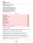
Cabinet Layout
FLOOR DRAIN
ACCESS HOLE
3 7/8"
20 3/8"
22"
.75 SHEET METAL DOOR FRONT
.63 MIN. CABINET DOOR
14 7/8"
29 1/4"
33 3/8" MIN.
34 3/8" MAX.
DRAIN
FLEXIBLE TUBING
3/8 I.D. PUMP MODEL (INCLUDED)
5/8 I.D. GRAVITY MODEL (NOT INCLUDED)
POTABLE WATER INLET
1/4" COMPRESSION FITTING
4"
AIR OUT
AIR IN
2 1/2"
2 3/4"
1" LEG ADJUSTMENT
(4) PLACES
September 2009
Page 3
1 1/2"
115 V
POWER CORD
3 3/4"
7 3/8"
3 1/4"
SCCG30 & SCCP30
Service Manual
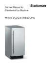
Air flow
The machine takes in room temperature air at the
lower right front and forces warm air out the lower
left front. Restricting the airflow will adversely affect
the ability of the ice machine to make ice.
On/Off Switch
Ice Making
Area
Warm Air Out
Air Intake
Scotsman Ice Systems are designed and
manufactured with the highest regard for safety
and performance. They meet or exceed the
standards of agencies like U.L.
Scotsman assumes no liability or responsibility of
any kind for products manufactured by Scotsman
that have been altered in any way, including the
use of any parts and/or other components not
specifically approved by Scotsman.
Scotsman reserves the right to make design
changes and/or improvements at any time.
Specifications and designs are subject to change
without notice.
September 2009
Page 4
SCCG30 & SCCP30
Service Manual
Water Quality
All water, including potable water supplied by
municipalities, contains some impurities or
minerals. Water absorbs impurities from the air as
rain and/or as it flows through the ground. Some of
the impurities are solid particles, these are known
as suspended solids, and a fine particle filter will
remove them. Other impurities are chemically
bonded to the water molecules, and cannot be
filtered out, these are called dissolved solids.
Filters and Treatment
In general, it is always a good idea to filter the
water. A water filter, if it is of the proper type, can
remove taste and odors as well as particles. Some
methods of water treatment for dissolved solids
include reverse osmosis, and polyphosphate
feeders.
RO Water
Ice made by this machine will have a lower mineral
content than the water it was made from. This is
due to the method of making ice. Purer water will
freeze first in the ice making molds. The reason for
this is that anything dissolved in water lowers the
water’s freezing temperature. This concentrates
most of the impurities in the ice machine water
reservoir where they may form hard deposits
known as scale. The machine dilutes the
concentration of minerals by over-filling the
reservoir during the harvest cycle (with the excess
water flowing down the drain). s. Between 2 and 4
pints of water flow into the unit each cycle.
Between 1 and 3.5 pints of that rinses the reservoir
and goes down the drain.
This machine can be supplied with Reverse
Osmosis water. A reverse osmosis system should
include post treatment to satisfy the R.O. water’s
potential aggressiveness. Deionized water is not
recommended.
Because water softeners exchange one mineral for
another, softened water may not improve water
conditions when used with ice machines. Where
water is very hard, softened water could result in
white, mushy cubes that stick together.
If in doubt about the water, contact a local point of
use water specialist for recommendations on water
treatment.
Some impurities will inevitably remain, and will stick
to the parts in the machine, and will cause
Installation Overview
malformed ice cubes. Eventually, built up mineral
The ice machine must:
scale can shorten machine life.
To keep the machine operating properly, these
impurities or minerals will have to be regularly
dissolved by an acid cleaning, using Scotsman Ice
Machine Scale Remover. Directions for this may be
found in the section under cleaning.
•
•
•
•
be connected to cold, potable water
be connected to a drain
be connected to the proper power supply
be able circulate air through the vents at the
front.
Note: Do not build in so that the door is recessed.
September 2009
Page 5
SCCG30 & SCCP30
Service Manual
Door Covering
Door Panel
Custom Panel
The ice machine is supplied without a conventional
door covering so it can be decorated to the user’s
preference. Scotsman offers several coverings
including white, black and stainless steel. In
addition, a custom built panel can be placed onto
the door.
A custom panel of wood or other material not
exceeding 15 lb can be attached to the door.
Attachment is from the ice side of the door. Holes
are provided in the door for this purpose.
See instructions in information packet to create and
attach a custom panel:
Door Panel Attachment
To attach a Scotsman supplied panel:
Note: If door swing is to be changed, it must be
done before panel is attached.
The panel will be held on by 6 sheet metal screws
and 2 machine screws.
1. Remove the gasket and retain for later use.
2. If the door panel is stainless steel, remove any
plastic covering the stainless steel panel.
3. Place the panel onto the outside of the door,
and secure it to the door using two machine
screws, located at the left center and right
center.
4. Fasten the panel to the door using the 6 sheet
metal screws. In the hinge area, use the
outermost screw holes.
5. Place the covers over the hinge areas, and
secure each cover to the door using a sheet
metal screw.
6. Insert hole plug over screw installed in step 5.
7. Return the gasket to its original position.
September 2009
Page 6
SCCG30 & SCCP30
Service Manual
Door Panel Attachment
Use Upper
Hole at the
Top
Scotsman
Door Panel
Gasket
Machine
Screw
Hole Plug
Use Lower
Hole at the
Bottom
Cover
September 2009
Page 7
SCCG30 & SCCP30
Service Manual
Custom Panel
A custom panel of wood or other material not
exceeding 15 lb can be attached to the door.
Attachment is from the ice side of the door. Holes
are provided in the door for this purpose.
To create and attach a custom panel:
10. Mount panel to door using wood screws or
supplied panel mounting screws.
Note: When installed Ice machine must be adjusted
for height to position top of door to desired
clearance.
• Panel width: 14 7/8”
• Panel height: Between 29 3/8” and 30 3/8”.
• Panel thickness: 5/8” to ¾”
1. Measure overall height of cabinet
opening where ice machine will be
(floor to bottom of countertop edge).
13 9/16"
6 25/32"
2. Determine desired kickplate
space (from bottom of door to floor).
This could be equal to the adjacent
cabinet’s kickplate space or another
space the user wants.
8 1/4"
13/16"
4 1/8"
13/32"
3. Subtract kickplate space from
cabinet opening.
4. Subtract 1/8 or more for clearance
space between top of door and
bottom of countertop edge from
cabinet opening. This is the
maximum door length.
14 11/16"
Ø 1/8"
TYP. (10)
5. Cut panel to width.
30 3/8"
29 3/8"
6. Cut panel to length (cabinet space
- kickplate space - top clearance =
length).
7. Determine top of panel.
8. Mark hole locations using drawing
on the back of these instructions.
Drawing assumes top of panel will
be flush with top of door. Measure
hole locations from the top of the
panel.
9. Drill pilot holes for wood screws.
Use drill stop to prevent drilling
through the panel.
13 31/64"
13/32"
{Centerline}
14 7/8"
September 2009
Page 8
SCCG30 & SCCP30
Service Manual
Door swing change
8. Remove the upper hinge and move it to the
The door can be attached to open with hinges on
door's opposite side, bottom location. Secure
the left or right using new brackets shipped loose in
using the original screws.
the ice bin. Retain all screws for re-use.
9. Remove the original lower hinge and move it to
the door's opposite side, upper location.
Secure using the original screws.
To change:
1. Remove innermost
screw holding each
hinge to cabinet, loosen
the other.
10. Install a screw removed in step 2 in outermost
hole of upper and lower cross braces.
11. Attach the door to the cabinet using the original
screws.
2. Slide hinges to the side
and remove door from
cabinet. Remove
screws loosened in step
1 from both hinge brackets.
12. Return kickplate and front service panel to their
original positions and attach to the cabinet
using the original screws.
3. Remove two screws securing top panel to
back, pull top panel back and remove from
cabinet.
Installation Notes
Built In Situations: If a finished floor is to be
installed in the area after the ice machine has been
built in, shims the expected thickness of the floor
should be installed under the unit to keep the
machine level with the planned floor level.
Door Hinge
4. Remove two screws at Bracket
the top and lift the door
hinge bracket out of the
cabinet. Replace with the
one supplied loose with
the machine. Fasten it to
the cabinet using the
original screws.
Installations on a slab: Use a pump model and
pump the water to the point of drainage. Pump
models will pump 1 story (10 feet) high.
5. Return the top panel to the cabinet and fasten
it with the original screws.
6. Remove kickplate and front service panel.
7. Remove two front screws and two bottom
screws holding the bottom cross brace to the
cabinet. Replace the brace with the one
supplied loose with the machine. Secure it
using the original screws.
Installations over a crawl space or basement:
Either gravity drain or pump model units may be
used, if there is not enough room behind the
machine for a drain/waste receptacle, the drain will
have to be below the floor.
Note: When installed in a corner, the door swing
may be limited due to handle contact with the wall
or cabinet face.
Screw Below
September 2009
Page 9
SCCG30 & SCCP30
Service Manual
Installation: Water & Drain
The recommended water supply tubing is ¼ inch
OD copper. Stainless steel flex or reinforced PVC
tube may also be used. Install an easily accessible
shut-off valve between the supply and the unit. This
shut-off valve should not be installed behind the
unit.
Drains
There are two types of ice machine models, one
that drains by gravity and one that has an internal
drain pump.
Drain Pump Model drain installation
Note: Do not use self-piercing type valves.
1. Locate the coil of 3/8” ID plastic drain tubing
secured to the back of the unit.
1. Remove the front service panel.
2. Route the plastic drain tube from the back of the
unit to the drain connection point.
IMPORTANT NOTE: Often an air gap is required by
local codes between the ice maker drain tube and
the drain receptacle.
Screw
Securing
Front Service
Panel
2. Route the tubing through the right hole in the
back to the inlet water solenoid valve inlet.
3. Install a compression fitting on the tubing and
connect to the inlet of the solenoid.
Water Inlet
Tube (field
supplied)
Drain Tube,
Route to
building drain
Back View, Drain Pump Model
September 2009
Page 10
SCCG30 & SCCP30
Service Manual
Gravity Drain
Caution: Restrictions in the drain system to the
machine will cause water to back up into the ice
storage bin and melt the ice. Gravity drain tubing
must be vented, have no kinks and slope to the
building drain. Air gaps are typically required by
local code.
1. Place the ice machine in front of the installation
opening. Adjust leveling legs to the approximate
height.
2. Remove the front service access panel and the
upper back panel.
Note: If you are connecting a gravity drain model
and the drain opening has been located in the floor
under the base pan according to the pre install
specifications, follow steps 3 through 5 to drain the
unit through the base. If not, proceed to step 6b.
3. Remove the clamp and barbed elbow and take
off the plastic cover in the base pan below the drain
hose.
4. Connect a straight 5/8” barbed connector to the
drain hose, securing with the clamp removed in
step 4.
5. Cut an 8” piece of 5/8” ID X 7/8” OD tygon (clear
plastic) tubing. Slide one end of the tube onto the
outlet of the barbed connector and secure with a
clamp. Leave the other end of the tube lying on the
floor of the base pan until the unit is positioned
over the floor drain.
6. Route the drain tube. Either a) Insert the drain
tube through the base pan into the floor drain or b)
Route the drain tube through the left hole in the
lower back panel and connect to barbed elbow and
secure with a clamp.
7. Reinstall the upper back panel.
8. Reinstall the service access panel. Level the
unit.
Barbed Elbow
Drain Hose
Water Inlet
Tube (field
supplied)
Drain Hose,
Route to
building drain
Back View, Gravity Drain Model
September 2009
Page 11
SCCG30 & SCCP30
Service Manual
Electrical & Start Up
The ice machine is supplied with a power cord. Do
not remove the grounding pin from the cord’s plug.
Do not use extension cords. Follow all codes.
Connect the machine to its own 115 volt, 15 amp
circuit.
1. If the electrical outlet for the ice maker is
behind the unit, plug in the unit.
Initial Start Up
1. Turn on the water supply.
2. Switch on the electrical power.
3. Move the On/Off switch to the ON position.
2. Position the unit in the installation opening.
3. Turn on the water supply. Make sure that the
ice maker is plugged in and the power is on.
4. Slide unit into installation opening, paying
careful attention to water supply and drain
connections. Do not kink!
5. Pour a couple of quarts of water into the ice
storage bin; on drain pump equipped machines
the drain pump should start and water should
pump out. Check for leaks.
6. Replace the service access panel.
4. The compressor will start and water will begin
to flow into the unit. When the reservoir is full,
water will start to drain from the machine. After
a few minutes the water pump and fan motor
will begin to operate and the first ice making
cycle will have begun.
7. Level the unit as needed.
Installation check list:
1. Has the unit been connected to the proper
water supply?
2. Has the water supply be checked for leaks?
3. Has the unit been connected to a drain?
4. Has the drain been tested for flow and leaks?
5. Has the unit been connected to the proper
electrical supply?
No adjustments are needed.
After about a half hour, ice will fall into the ice
storage bin. The machine makes 12 cubes per
batch. It is normal for the first batches of ice to
melt, that continues until the bin has cooled. It will
take 16 to 24 hours of continuous run time to fill the
ice bin. When the bin is full of ice, the ice machine
will shut off. It will automatically restart when the
ice level falls, either from use or normal meltage.
6. Has the unit been leveled?
7. Have all packing materials been removed from
the machine?
Has the door covering been installed?
8.
September 2009
Page 12
SCCG30 & SCCP30
Service Manual
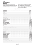
Cube Size Adjustment
The size of the ice cubes is determined by how
long the ice machine is in the freezing cycle. That
is controlled by the cube size thermostat.
Side Views of Cubes
The cube size thermostat's sensing portion is
attached to the suction tube, near the outlet of the
evaporator. As the machine makes ice, the
temperature of the suction tubing falls. When it
reaches a preset point, the thermostat's contacts
close and connect power to the electronic timer.
The electronic timer finishes the freeze cycle.
Too Small, Adjust Cycle Longer
Adjustment
There is only one proper ice cube size, see the
diagram to the right. If the cubes are not the correct
size, adjust the cube size thermostat.
Just Right
Rotate the cube size thermostat's adjustment
screw clockwise to increase the size of the cube.
Rotate the cube size thermostat's adjustment
screw counter clockwise to make the ice cube size
smaller.
September 2009
Page 13
Too Large, Adjust Cycle Shorter
SCCG30 & SCCP30
Service Manual
Harvest Time Adjustment
The harvest time can be adjusted so that all the ice
is released during the harvest period, with a few
seconds extra for a safety margin. The adjustment
range is between 2 to 5 minutes.
There is an adjustment screw on the surface of the
electronic timer. Rotate the screw CCW to reduce
harvest time, and CW to increase it. It should be
set to match the machine's performance. If the
machine takes 2 and a half minutes to release the
ice, the harvest time should be set to about 3
minutes.
September 2009
Page 14
SCCG30 & SCCP30
Service Manual
Use
No special instructions are needed for use. Just
take as much ice as you need, the machine will
replace it. A scoop is provided, and it can be stored
in the machine using the loop of tubing on the right
side as a holder.
The machine can be shut off anytime by moving
the On/Off switch to OFF.. The machine will shut
off immediately.
What shouldn’t be done?
Never keep anything in the ice storage bin that is
not ice. Objects like wine or beer bottles are not
only unsanitary, but the labels can slip off and plug
up the drain.
Never allow the machine to operate without regular
cleaning. The machine will last longer if it is kept
clean. Regular cleaning should happen at least
once per year, and preferably twice. Some water
conditions will dictate even more frequent cleaning
of the ice making section, and some carpets or
pets will dictate more frequent cleaning of the
condenser.
Normal cubes are tapered cylinders. If the cubes
are ragged and mis-shaped, mineral scale must be
removed from the ice making system
Maintenance
There are 5 things to keep clean:
1. The outside cabinet & door.
2. The ice storage bin.
3. The condenser.
4. The ice making system.
Noise:
The ice machine is designed for quiet operation,
but will make some noise during the ice making
cycle. During a freezing cycle, it is normal to hear
the fan moving air and the water pump circulating
water. Ice hitting the bin or ice in the bin can be
heard during harvest.
If ice making noise is objectionable, an appliance
grade timer can be added to the power supply. Set
the timer to turn the machine off at the time(s) of
day when the noise is most objectionable.
5. The ice scoop.
How to clean the cabinet.
Wipe off any spills on the surface of the door and
handle as they occur. If anything spilled on the
door or gasket dries onto the surface, wash with
soap and warm water to remove.
How to clean the ice storage bin.
The ice storage bin should be sanitized
occasionally. It is usually convenient to sanitize the
bin after the ice making system has been cleaned,
and the storage bin is empty.
A sanitizing solution can be made of 1 ounce of
household bleach and two gallons of hot (95 oF. –
115oF.) water. Use a clean cloth and wipe the
interior of the ice storage bin with the sanitizing
solution, pour some of the solution down the drain.
Allow to air dry.
September 2009
Page 15
SCCG30 & SCCP30
Service Manual
How to clean the condenser and winterize.
Condenser cleaning
Winterizing
The condenser is like the radiator on a car, it has
fins and tubes that can become clogged with dirt
and lint. To clean:
1. Clean the ice making system.
2. Open the door and push and release the On/Off
switch to turn the machine off.
1. Remove the kickplate and front service panel.
3. Turn off the water supply.
2. Locate the condenser surface.
4. Drain the water reservoir by removing the rubber
cap under the reservoir - it's near the back wall of
the ice storage bin.
Rubber Cap
3. Vacuum the surface, removing all dust and lint.
Caution: Do not dent the fins.
5. Disconnect the incoming water line at the inlet
water valve.
4. Return the kickplate and front service panel to
their original positions. Fasten them to the cabinet
using the original screws.
6. Open the door, push and release the on/off
switch to turn the machine on.
7. Blow air through the inlet water valve; a tire
pump could do the job.
8. Drain pump models should have about 1/2
gallon of RV antifreeze (propylene glycol) poured
into the ice storage bin drain.
Note: Automotive antifreeze must NOT be used.
9. Switch off and unplug the machine.
September 2009
Page 16
SCCG30 & SCCP30
Service Manual
How to remove scale from the ice making system.
1. Scoop out all of the ice, either discard it or save
it in an ice chest or cooler.
2. Switch the machine Off.
3. Pour 8 ounces of Scotsman Ice
Machine Scale Remover
(available from a local Scotsman
Distributor or Dealer) into the ice
machine reservoir.
4. Switch the machine On.
Pour Scale
Remover Here
5. Operate the machine for about
2 hours.
6. Pour a gallon of hot (95oF. –
115oF.) water into the bin to melt
ice formed during the cleaning
process and to flush out the drain.
7. Clean the bin liner of mineral
scale by mixing some ice machine
scale remover and hot water, and
using that solution to scrub the
scale off of the liner.
8. Rinse the liner with hot water.
9. Sanitize the bin interior.
10. Replace the ice removed in step 1.
The ice scoop should be washed regularly, wash it
just like any other food container.
September 2009
Page 17
SCCG30 & SCCP30
Service Manual
System Information
Overall:
•
•
•
•
•
•
•
•
•
•
•
•
•
•
•
•
•
•
•
Refrigerant: 8 oz R-134a
Compressor: Hermetic, 700 BTUH
Condenser: Forced draft
Fan blade: 3 blade, 6 inch
Evaporator: Inverted, 12 cube cells. copper,
continuous serpentine
Metering device: Cap tube
Defrost method: Hot gas bypass with water
assist
Spray method: 6 water jets
Water charge: 30 ounces
Water valve: 115 volt solenoid, .19 GPM
Water fill time: Varies with harvest time
Spray pump: Pedestal type.
Drain pump: Magnetic drive, controlled by
pressure switch
Purge method: Overflow standpipe
Control method: Electronic timer with electro
mechanical cube size thermostat
Cycle control: Reverse acting thermostat
Cube size adjustment: Thermostat cut in
change
Harvest cycle adjustment: Harvest timer
change, range between 2 and 5 minutes.
Bin control: Thermostat. Opens on
temperature fall, Cut Out: 35 degrees F. Cut
In 45 degrees F. Range is adjustable.
Electrical Components:
•
•
•
•
•
•
•
•
•
•
Electrical Sequence:
Compressor
Fan motor
Spray pump motor
Drain pump motor
Drain pump switch
Inlet water solenoid valve
Freeze & harvest timer
Cube size thermostat
Hot gas valve
Bin thermostat
The machine uses a temperature initiated, timed
cycle to make ice.
A closed bin thermostat connects power to the
compressor and electronic timer. The timer NO
contacts close, connecting power to the water and
hot gas solenoids.
The compressor starts, the inlet water solenoid
valve opens and fills the reservoir. The harvest
timer starts. At the end of the pre-set harvest time,
the timer will open the NO contacts, stopping the
inlet water valve and hot gas valve. At the same
time, it closes the NC contacts, powering the fan
and pump motors. This is the beginning of the
freeze cycle.
The freeze cycle continues until the cube size
contacts close, this starts a freeze timer. No other
changes occur until the freeze timer expires, when
the NC contacts open and the NO contact close,
starting the harvest cycle.
The harvest cycle is time controlled. At the end of
the harvest cycle the unit returns to a freeze cycle.
Bin control.
The machine's on and off modes are regulated by a
bin thermostat. The cap tube for the bin thermostat
is in the tube that holds the scoop. The machine
will only begin ice making when the thermostat's
contacts close. The machine will stop ice making
whenever the bin thermostat contacts open.
September 2009
Page 18
SCCG30 & SCCP30
Service Manual
Water System
The water system consists of a water pump, inlet
water solenoid valve, reservoir with overflow
standpipe and spray platform.
Harvest cycle: The inlet water solenoid valve is
open during the harvest cycle. Water flows through
it to the top of the machine and onto the evaporator
platen. The water flows across the platen, warming
it up to assist in releasing the ice. Water drains
from the platen through drain holes at the platen
corners. That water, now chilled by contact with the
evaporator platen, drains into the reservoir. When
the reservoir is full, excess water drains out the
standpipe. When harvest is complete, the inlet
water solenoid closes and water stops flowing into
the machine.
Standpipe
Inlet Water Solenoid Valve
Harvest Cycle Water Schematic
Freeze cycle: The water pump takes water from
the reservoir and forces it through the 6 spray jets,
causing the water to contact the inverted cups of
the evaporator. Unfrozen water falls back into the
reservoir. As ice forms in the cups, the water level
in the reservoir fails. This continues until the
harvest cycle starts.
Evaporator
Pump
Reservoir
Drain
Freeze Cycle Water Schematic
September 2009
Page 19
SCCG30 & SCCP30
Service Manual
Components
Model and
Serial Tag
Location
Bin Thermostat Bracket and Scoop
Model and Serial Plate Location
Evaporator Platen
Evaporator & Top of Unit
Inlet Water Solenoid Valve
Condenser and Bin Thermostat
September 2009
Page 20
SCCG30 & SCCP30
Service Manual
Performance Information
Listed cycle times are after the 3rd consecutive cycle, will vary a minute or so, and will be longer for built
in units.
Freeze Cycle, Minutes
Water
Temperature
Air Temperature
100
90
80
70
60
50
100
60
46
45
43
42
40
90
54
44
42
40
38
36
80
45
40
38
37
35
34
70
40
37
35
33
32
30
60
31
30
27
26
24
23
50
24
23
22
21
20
19
40
23
21
20
19
18
18
Harvest time is usually 2 minutes, longer in very
cold conditions.
Total Cycle, Minutes
Water
Temperature
Air Temperature
100
90
80
70
60
50
100
62
48
47
45
44
42
90
56
46
43
42
40
38
80
47
42
39
39
37
36
70
42
39
37
35
33
32
60
32
32
29
26
26
23
50
26
25
23
23
22
24
40
25
22
22
21
24
23
Ice per cycle: 1/2 lb
Water drained / cycle: Varies by harvest cycle
length and purge setting. Typically about 3 pints.
Compressor amps: 2.9 - 3.1
September 2009
Page 21
SCCG30 & SCCP30
Service Manual
Refrigeration System
Suction Pressure
70
60
50
PSIG
40
30
20
10
0
Time
Discharge Pressure
140
120
100
PSIG
80
60
40
20
0
Time
September 2009
Page 22
SCCG30 & SCCP30
Service Manual
Service Diagnosis
No Ice
Problem
Likely Cause
Probable Solution
No power to unit
Power disconnected
Check breaker or fuse. Reset or
replace, restart and check
Dirty condenser
Clean condenser
Restricted location, intake air too
hot or blocked
Eliminate restriction, have machine
moved
Evaporator thermostat not sensing
properly
Check thermostat
Spray jets dirty
Remove spray platform and clean
spray jets
Inlet water valve leaks through
during freeze
Check inlet water valve
Low on refrigerant
Check cube formation,
Connected to hot water
Check for bleed thru from / missing
check valve in building water
supply
Spray pump not pumping
Check pump motor
Fan motor not turning
Check fan motor, check fan blade
Pump hose disconnected
Check hose
Water leak
Check curtain, sump drain cap
Very low on refrigerant
Add access valve, add refrigerant
as a test. If unit makes ice, find and
correct leak.
Very long freeze cycle
Check compressor start
components
Cannot make ice
Compressor not operating
Check compressor voltage
Check compressor windings
Hot gas valve leaks through during
freeze
Check hot gas valve for hot outlet
during freeze
Compressor inefficient
Check compressor amp draw, if
low and all else is correct, change
compressor
September 2009
Page 23
SCCG30 & SCCP30
Service Manual
Service Diagnosis
Makes excessive noise
Problem
Likely Cause
Probable Solution
Blade is bent
Replace fan blade
Fan motor mount is broken
Replace motor mount
Compressor vibrates
Mounting loose
Check mounting
Water pump vibrates
Pump bearings worn
Replace pump
Panels vibrate
Mounting screws loose
Tighten screws
Problem
Likely Cause
Probable Solution
Ice wrong size
Environment changed
Adjust cube size
Hot gas valve does not open
Check voltage to coil when unit is
in harvest, check controller
indicator light.
Water temperature very low
Adjust harvest time
Problem
Likely Cause
Probable Solution
Spray pattern poor
Spray jets dirty
Clean jets
Runs out of water
Water leaking from reservoir
Correct leak
High TDS water supply
Groundwater supply
Treat water
Likely Cause
Probable Solution
Gravity drain hose has air block
Check for kinks or traps
Pump model switch not starting
pump
Check / replace switch
Fan blade vibrates
Makes ice, does not harvest
Little heat to evaporator
Makes poor quality ice
Makes ice, but melts rapidly
Problem
Restricted drain, water in
bin
September 2009
Page 24
SCCG30 & SCCP30
Service Manual
Removal and Repair
Bin Thermostat
9. Reverse to reassemble.
1. Disconnect electrical power.
Curtain
1. Shut unit off.
2. Loosen both thumbscrews holding curtain
bracket to freezing chamber.
Electrical Shock
Hazard.
Disconnect electrical
power before
beginning removal
3. Pull out and remove curtain with bracket from ice
machine.
2. Remove service panel.
4. Reverse to reassemble.
3. Remove back panel.
Spray Platform
Note: If unit is built in it must be pulled out to
change the bin thermostat.
1. Remove curtain.
4. Pull cap tube out from the back of the ice
storage bin and cap tube holder.
2. Lift spray platform up until it disconnects from its
fitting.
3. Pull forward and remove from the ice machine.
5. Remove two screws and the bin thermostat
contact section from its mounting bracket.
6. Disconnect two wires from the bin thermostat
contact section and remove the thermostat from
the ice machine.
4. Reverse to reassemble.
Water Pump
1. Disconnect electrical power.
2. Remove spray platform
7. Reverse to reinstall.
3. Remove back panel.
Inlet Water Solenoid Valve
Note: If unit is built in it must be pulled out to
change the water pump.
1. Disconnect electrical power.
2. Remove service panel.
4. Disconnect power and ground wires from pump
motor.
3. Shut water supply OFF.
4. Disconnect inlet water supply tube from inlet
water solenoid valve.
5. Rotate pump body CW and lift up to remove it.
6. Reverse to reassemble.
5. Unplug wire harness from valve coil.
6. Remove two screws holding valve to chassis.
7. Squeeze hose clamp larger and push away from
solenoid valve outlet.
8. Pull hose from outlet of valve.
September 2009
Page 25
SCCG30 & SCCP30
Service Manual
Removal and Repair
Cube Size Thermostat
9. Disconnect wires from cube size thermostat.
1. Disconnect unit from electrical power.
10. Remove two screws holding cube size
thermostat to bracket. Pull cube size thermostat
from the machine.
11. Route new cube size thermostat bulb and cap
tube from the front, through the hole in the air baffle
and into the back of the unit.
Electrical Shock
Hazard.
Disconnect electrical
power before
beginning removal
12. Attach cube size thermostat to thermostat
bracket, attach wires.
2. Remove door.
Note: Replacement thermostat wiring may be
different from the original. Check for instructions.
3. Remove top panel.
4. Remove service panel.
13. Attach bracket to cabinet.
5. Remove back panel.
14. Route cube size cap tube and bulb up the back
of the machine and into the evaporator area.
6. Cut cable tie holding cube size bulb in
evaporator well. Pull bulb out of well.
15. Insert bulb into evaporator well. Secure with tie
wrap.
16. Return all panels to their normal positions ans
secure with the original screws.
17. Reconnect power. Test machine, adjust cube
size as needed.
Bulb Well
7. Pull cube size cap tube and bulb from
evaporator area and allow to hang freely behind
machine.
Harvest Timer
1. Disconnect electrical power.
8. Remove two screws holding thermostat bracket
to cabinet. Drop bracket down and pull forward to
get access to wires and screws.
Electrical Shock
Hazard.
Disconnect electrical
power before
beginning removal
2. Remove service panel.
3. Remove screw in center of timer, pull out and
disconnect wires.
4. Reverse to reassemble.
September 2009
Page 26
SCCG30 & SCCP30
Service Manual
Removal and Repair - Cabinet Removal
Certain components require the removal of the
cabinet for repair access.
12. Pull clip up and pull water inlet elbow out of
inner elbow.
1. Shut machine off, if making ice, melt ice with hot
water.
13. Push inner elbow back and rotate it until it
points straight up, then push it back through the
hole in the back of the freezing compartment.
2. Remove all ice.
Inlet Elbow
3. Drain reservoir.
4. Remove service panel and kick plate.
5. Remove back panel.
Inner
Elbow
6. Disconnect electrical power.
Clip
Electrical Shock
Hazard.
Disconnect electrical
power before
beginning removal
7. Disconnect water and drain tubing.
8. Remove door.
9. Remove top panel.
10. Remove curtain & hanger.
14. Remove two screws holding freezing
compartment brackets to cabinet, lift brackets up.
Bracket
11. Locate elbows where water flows onto the
evaporator platen.
September 2009
Page 27
SCCG30 & SCCP30
Service Manual
15. Lift evaporator platen up and tilt back enough
for bin assembly to clear the base.
18. Remove 1 screw at each corner of the base.
19. Lift bin assembly off the base.
Note: Prop evaporator assembly up. A 3' length of
3/4" PVC tubing with one end inserted into the cup
mold and the other against the base will hold it up.
The hot gas valve, fan motor, condenser and
compressor are now exposed for service.
16. Remove air baffle.
Air Baffle
17. Unplug wire harness connector (at back of bin).
September 2009
Page 28
SCCG30 & SCCP30
Service Manual
Refrigeration Service
This ice machine use R-134a type refrigerant.
There are specific rules for handling that
refrigerant.
To check for system pressures, add a field supplied
clamp-on type service valve as a temporary means
of system access. After diagnosis and before final
repair, replace the clamp-on type valve with valves
that are brazed onto the process tubes of the
system.
Use a low flow of dry nitrogen when brazing on the
system.
Install a new filter drier when replacing a
refrigeration component or after a refrigerant leak
repair.
Evacuate the system to at least 300 microns and
use a micron gauge to measure the evacuation
level.
Weigh in the nameplate charge. The machine is
critically charged and a partial ounce mis-charge
will affect performance.
September 2009
Page 29