1
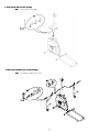
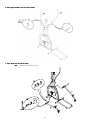
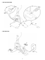
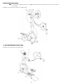
003-3790.060112.D
Para obtener este manual en Español Latino Americano vaya a: http://www.schwinnfitness.com.
Table of Contents
Before Assembly
2
Hardware
4
Important Safety Instructions
2
Assembly
4
Specifications and Tools
3
Adjustments
Parts
3
12
Nautilus, Inc., (800) NAUTILUS / (800) 628-8458, www.NautilusInc.com - Customer Service: North America (800) 605-3369, [email protected] | Asia Pacific & Latin America (360)
859-5180, [email protected] | Patent information: This product may be covered by US and Foreign Patents and Patents Pending. See Product for more information. | Printed in China | © 2010
Nautilus, Inc., All rights reserved. ™ and ® indicate a trademark or registered trademark. Nautilus, Inc. (www.NautilusInc.com) trademarks include NAUTILUS®, BOWFLEX®, SCHWINN® and
UNIVERSAL® and respective logos. Other trademarks are the property of their respective owners.
Before Assembly
Select the area where you are going to set up and operate your machine. For safe operation, the location must be on a hard, level surface. Allow a workout area
of minimum 70.5” x 107” (179 cm x 272 cm).
Follow these basic points when you assemble your machine:
1. Read and understand the “Important Safety Instructions” before assembly.
2. Collect all the pieces necessary for each assembly step.
3. Using the recommended wrenches, turn the bolts and nuts to the right (clockwise) to tighten, and the left (counterclockwise) to loosen, unless instructed otherwise.
4. When attaching 2 pieces, lightly lift and look through the bolt holes to help insert the bolt through the holes.
5. The assembly requires 2 people.
Important Safety Instructions
This icon means a potentially hazardous situation which, if not avoided, could result in death or serious injury. Obey the following warnings:
•
•
•
•
•
•
•
•
•
•
•
•
•
Read and understand all warnings on this machine.
Carefully read and understand the Assembly Manual.
Keep bystanders and children away from the product you are assembling at all times.
Do not connect power supply to the machine until instructed to do so.
Do not assemble this machine outdoors or in a wet or moist location.
Make sure assembly is done in an appropriate work space away from foot traffic and exposure to bystanders.
Some components of the machine can be heavy or awkward. Use a second person when doing the assembly steps involving these parts. Do not do steps that
involve heavy lifting or awkward movements on your own.
Set up this machine on a solid, level, horizontal surface.
Do not try to change the design or functionality of this machine. This could compromise the safety of this machine and can void the warranty.
If replacement parts are necessary use only genuine Nautilus® replacement parts and hardware. Failure to use genuine replacement parts can cause a risk to users, keep
the machine from operating correctly and void the warranty.
Do not use the machine until it has been fully assembled and inspected for correct performance in accordance with the Owner’s Manual.
Read and understand the complete Owner’s Manual supplied with this machine before first use. Keep the Owner’s and Assembly Manuals for future reference.
Do all assembly steps in the sequence given. Incorrect assembly can lead to injury.
2
Specifications and Tools
Included
Not Included
#2
(recommended)
4mm
5mm
6mm (x2)
(recommended)
Parts
R”) and left (“LL”) parts to assist with assembly.
A decal has been applied to all right (“R
Item
Qty
1
1
2
Description
Item
Qty
Frame
9
2
Pedals
1
Front Stabilizer
10
1
Leg, Right
3
1
Water Bottle Holder
11
1
Leg, Left
4
1
Console
12
1
Lower Left Handlebar Arm
5
1
Console Mast
13
1
Lower Right Handlebar Arm
6
1
Pedal Arm, Left
14
1
Upper Left Handlebar Arm
7
1
Pedal Arm, Right
15
1
Upper Right Handlebar Arm
8
1
Rail Assembly
3
Description
Hardware
Item
Qty
A
6
B
Description
Item
Qty
Flat Head Hex Screw, M8x25
J
2
Shaft
18
Button Head Hex Screw, M8x15
K
6
Flat Washer, M6
C
8
Flat Washer, M8
L
4
Button Head Hex Screw, M6x12
D
18
Spring Washer, M8
M
2
Wave Washer,Small (D16.5)
E
4
Flat Washer, Wide
N
2
Sleeve, Plastic
F
2
Washer
O
2
Wave Washer,Large (D20)
G
6
Button Head Hex Screw, M6x15
P
4
Plastic Washer (D16.2)
H
4
Carriage Bolt, M6x25
Q
6
Washer, Curved
I
2
Pedal Mount Plate
Assembly
Note:
Do not fully tighten the Hardware until the machine is completely assembled.
1. Attach Front Stabilizer to Frame
4
Description
2. Attach Rail Assembly to Frame Assembly
3. Connect the Console Cable
Note:
The cables must be fully connected for the Console to operate. Do not crimp the Console Cable.
5
4. Attach Console Mast to Frame Assembly
Note:
Do not crimp the Console Cable.
5. Attach Lower Handlebar Arms to Frame Assembly
Note:
Only tighten this Hardware until secure.
6
6. Attach Upper Handlebar Arms to Frame Assembly
7. Attach Pedal Arms to Frame Assembly
Note:
Only tighten this Hardware until secure.
7
8. Attach Legs to Frame Assembly
9. Attach Pedals to Legs
8
10. Attach Console to Frame Assembly
Note:
Be sure the switch on the back of the Console is set to E. The cables must be fully connected for the Console to operate. Do not crimp the
Console Cable.
* Hardware is pre-installed on Console and not on the Hardware Card.
11. Attach Water Bottle Holder to Frame Assembly
* Hardware is pre-installed and not on the Hardware Card.
9
12. Tighten all Hardware
Note:
Fully tighten all Hardware from the previous steps except where noted to only secure.
13. Install Batteries in Console
Note:
The console uses D size batteries (LR20), which are not included. Make sure that the batteries point in the direction of the +/– indicators in
the battery bay. If you use rechargeable batteries, the optional power adapter will not recharge the batteries.
Do not mix old and new batteries.
Do not mix alkaline, standard (carbon-zinc), or rechargeable (Ni-Cd, Ni-MH, etc) batteries.
Final Inspection
Inspect your machine to ensure that all fasteners are tight and components are properly assembled.
Do not use until the machine has been fully assembled and inspected for correct performance in accordance with the Owner’s Manual.
10
Optional Power Adapter
The console for your machine can operate on battery power or AC power. For AC power, it is necessary to order the optional Power Adapter. If batteries and the Power
Adapter are installed, the console will use the Power Adapter to operate.
Note:
If you use rechargeable batteries, the optional Power Adapter will not recharge the batteries.
After the machine is fully assembled, connect the Power Adaptor to the console and the wall outlet.
NOTICE:
If you use a power adapter for your elliptical, make sure that the cord stays clear of the path of the arms and pedals. Attach the cord to
the machine as shown:
NOTICE:
It is recommended to remove batteries when they are not used, to avoid damage from battery corrosion.
To order the optional Power Adapter, go to:
www.schwinnfitness.com/powersupply
Or call 1 (800) 605–3369.
FCC Compliance
Changes or modifications to this unit not expressly approved by the party responsible for compliance could void the user’s authority to operate the equipment.
Note:
This equipment has been tested and found to comply with the limits for a Class B digital device, pursuant to Part 15 of the FCC Rules. These
limits are designed to provide reasonable protection against harmful interference in a residential installation. This equipment generates, uses
and can radiate radio frequency energy and, if not installed and used in accordance with the instructions, may cause harmful interference to
radio communications.
However, there is no guarantee that interference will not occur in a particular installation. If this equipment does cause harmful interference
to radio or television reception, which can be determined by turning the equipment off and on, the user is encouraged to try to correct the
interference by one or more of the following measures:
•
•
•
Reorient or relocate the receiving antenna.
Increase the separation between the equipment and receiver.
Connect the equipment into an outlet on a circuit different from that to which the receiver is connected.
Consult the dealer or an experienced radio/TV technician for help.
11
Adjustments
Moving the Machine
Do not move the machine without aid. Injury to you or damage to the machine
can occur.
1. Remove the power cord (if equipped).
2. Use the back of the Rail Assembly to carefully lift the machine onto the transport
rollers.
3. Push the machine into position.
4. Carefully lower the machine into position.
Leveling the Machine
The machine needs to be leveled if your workout area is uneven or if the Rail Assembly is
slightly off the floor. To adjust:
1. Place the machine in your workout area.
2. Stand on the Rail Assembly for approximately 20 seconds.
3. Step off of the machine
4. Loosen the lock nut and adjust the levelers until they all contact the floor.
5. Adjust until the machine is level. Tighten lock nuts.
12
13
14
15
Printed in China