1
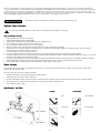
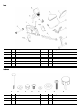
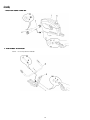
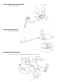
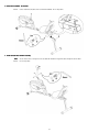
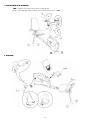
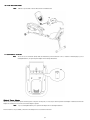
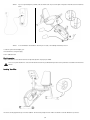
003–3802–042310A
Nautilus, Inc., World Headquarters, 16400 SE Nautilus Dr. Vancouver, WA, USA 98683, (800) NAUTILUS / (800) 628-8458, www.NautilusInc.com - Customer Service: North America (800) 605-3369,
[email protected] | Europe, Middle East & Africa 49 02203 2020 0, [email protected] | Germany & Austria + 49 02203 2020 0, Switzerland + 41 26 460 77 66, United Kingdom
+ 44 1908 267 345, Asia Pacific & Latin America (360) 859-5180, [email protected] | Patent information: This product may be covered by US and Foreign Patents and Patents Pending. See
Product for more information. | Printed in China | © 2010 Nautilus, Inc., All rights reserved. ™ and ® indicate a trademark or registered trademark. Nautilus, Inc. (www.nautilus.com) trademarks include
NAUTILUS®, BOWFLEX®, SCHWINN® and UNIVERSAL® and respective logos. Other trademarks are the property of their respective owners.
Para obtener este manual en Español Latino Americano vaya a: http://www.schwinnfitness.com.
Important Safety Instructions
This icon means a potentially hazardous situation which, if not avoided, could result in death or serious injury.
Obey the following warnings:
•
•
•
•
•
•
•
•
•
•
•
•
•
Read and understand all warnings on this machine.
Carefully read and understand the Assembly Manual.
Keep bystanders and children away from the product you are assembling at all times.
Do not connect power supply to the machine until instructed to do so.
Do not assemble this machine outdoors or in a wet or moist location.
Make sure assembly is done in an appropriate work space away from foot traffic and exposure to bystanders.
Some components of the machine can be heavy or awkward. Use a second person when doing the assembly steps involving these parts. Do not do steps that
involve heavy lifting or awkward movements on your own.
Set up this machine on a solid, level, horizontal surface.
Do not try to change the design or functionality of this machine. This could compromise the safety of this machine and will void the warranty.
If replacement parts are necessary use only genuine Nautilus® replacement parts and hardware. Failure to use genuine replacement parts can cause a risk to users, keep
the machine from operating correctly and void the warranty.
Do not use or put the machine into service until the machine has been fully assembled and inspected for correct performance in accordance with the Owner’s Manual.
Read and understand the complete Owner’s Manual supplied with this machine before first use. Keep the Owner’s Manual for future reference.
Do all assembly steps in the sequence given. Incorrect assembly can lead to injury or incorrect function.
Before Assembly
Select the area where you are going to set up and operate your machine. For safe operation, the location must be on a hard, level surface. Allow a workout area of
minimum 100” x 58” (254cm x 147cm).
Follow these basic points when you assemble your machine:
1. Read and understand the “Important Safety Instructions” before assembly.
2. Collect all the pieces necessary for each assembly step.
3. Using the recommended wrenches, turn the bolts and nuts to the right (clockwise) to tighten, and the left (counterclockwise) to loosen, unless instructed otherwise.
4. When attaching 2 pieces, lightly lift and look through the bolt holes to help insert the bolt through the holes.
5. The assembly can require 2 people.
Specifications and Tools
Included
Not Included
6mm
(recommended)
13mm/17mm
(recommended)
15mm
2
Parts
Item
Qty
1
1
2
Description
Item
Qty
Main Unit
8
1
Side Handlebars
1
Front Stabilizer
9
1
Console Mast
3
1
Rear Stabilizer
10
1
Console
4
1
Seat Rail
11
1
Pedal, Left (L)
5
1
Seat Bracket Assembly
12
1
Pedal, Right (R)
6
1
Seat Bottom
13
1
Water Bottle Holder
7
1
Seat Back
Item
Qty
Description
Description
Hardware
Item
Qty
A
4
Carriage Bolt M8 x 65
E
12
Flat Washer
B
5
Arc Washer
F
2
Rubber Limit Pad
C
4
Acorn Nut
G
8
Phillips Head Screw M6 x 35
D
15
Hex Screw M8 x 15
H
1
Adjustment Knob
Description
3
Assembly
1. Attach Front Stabilizer to Main Unit
2. Install Handlebar to Seat Bracket
NOTICE:
Do not crimp cable from Handlebar.
4
3. Attach Seat Bottom and Seat Back to Seat Bracket
NOTICE:
Do not crimp cable.
4. Slide Seat Assembly onto Seat Rail
NOTICE:
Do not crimp cables.
5. Install Seat Rail Assembly to Main Assembly
NOTICE:
Connect Heart Rate (HR) cables from Seat Rail and Main Unit. Do not crimp cables.
5
6. Attach Rear Stabilizer to Seat Rail
NOTICE:
Connect Heart Rate (HR) cables from Seat Rail and Handlebar. Do not crimp cables.
7. Install Console Mast to Main Assembly
Note:
NOTICE:
You can attach a wire (or string) to the Console Cable and HR Cable to help pull the cables through the Console Mast.
Do not crimp cables.
6
8. Install the Console to the Console Mast
Note:
NOTICE:
Hardware is pre-installed on Console and not on Hardware Card.
Do not crimp cables. Make sure that the switch on the back of the Console is set to B.
9. Install Pedals
7
10. Install Water Bottle Holder
Note:
Hardware is pre-installed on Console Mast and not on Hardware Card.
11. Install Batteries in Console
Note:
The console uses D size batteries (LR20). Make sure the batteries point in the direction of the +/– indicators in the battery bay. If you use
rechargeable batteries, the optional power adapter will not recharge the batteries.
Optional Power Adapter
The console for your machine can operate on battery power or AC power. For AC power, it is necessary to order the optional Power Adapter. If batteries and the Power
Adapter are installed, the console will use the Power Adapter to operate.
Note:
If you use rechargeable batteries, the optional Power Adapter will not recharge the batteries.
After the machine is fully assembled, connect the Power Adaptor to the console and the wall outlet.
8
NOTICE:
If you use a power adapter for your bike, make sure that the cord stays clear of the path of the pedals. Attach the cord to the machine as
shown:
NOTICE:
It is recommended to remove batteries when they are not used, to avoid damage from battery corrosion.
To order the optional Power Adapter, go to:
www.schwinnfitness.com/powersupply
Or call 1 (800) 605–3369.
Final Inspection
Inspect your machine to ensure that all fasteners are tight and components are properly assembled.
Do not use or put the machine into service until the machine has been fully assembled and inspected for correct performance in accordance with the Owner’s
Manual.
Leveling Your Bike
The levelers are the polygonal end caps on the Rear Stabilizer. Turn the end cap to adjust the level. Make sure the bike is level and stable before you exercise.
9
Printed in China