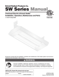
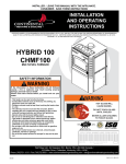
1
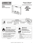
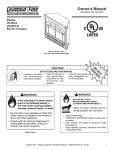
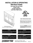
Owner’s Manual
Installation and Operation
Models:
CF230E-B
CF260E-B
Electric Fireplace/Insert
DO NOT DISCARD THIS MANUAL
•
Important operating •
and maintenance
instructions included.
Read, understand
and follow these
instructions for safe
installation and
operation.
Leave this manual with
party responsible for
use and operation.
WARNING
WARNING
HOT! DO NOT TOUCH.
SEVERE BURNS MAY RESULT.
CLOTHING IGNITION MAY RESULT.
If the information in these instructions is not followed exactly, a
fire may result causing property
damage, personal injury, or death.
• Do not store or use gasoline or other flammable vapors and liquids in the vicinity of
this or any other appliance.
• Comply with all minimum clearances to
combustibles as specified. Failure to
comply may cause house fire.
•
T
O
N RD
O A
D SC
I
D
CAUTION
Glass and other surfaces are hot
during operation and cool down.
•
•
•
•
Keep children away.
CAREFULLY SUPERVISE children in same room
as heater.
Alert children and adults to hazards of high
temperatures.
Keep clothing, furniture, draperies and other
combustibles away.
Made in China
Heat & Glo • CF230E-B & CF260E-B • 4038-894 Rev C • 11/05
1
Read this manual before installing or operating this heater.
Please retain this owner’s manual for future reference.
Congratulations!
Congratulations on selecting a Heat & Glo electric fireplace/
insert. The insert you have selected is designed to provide
the utmost in safety, reliability and efficiency.
As the owner of a new fireplace/insert, you’ll want to read and
carefully follow all of the instructions contained in this owner’s
manual. Pay special attention to all cautions and warnings.
The information contained in this owner’s manual unless noted
otherwise, applies to all models.
Your new Heat & Glo electric fireplace/insert will give you
years of durable use and trouble-free enjoyment. Welcome
to the Heat & Glo family of fireplace products!
This owner’s manual should be retained for future reference.
We suggest you keep it with your other important documents
and product manuals.
Homeowner Reference Information
We recommend that you record the following pertinent
information about your heater:
Model Name:
Date purchased/installed:
Serial Number:
Location on heater:
Dealership purchased from:
Dealer phone:
Notes:
Listing Label Information/Location
The model information regarding your specific heater can be found on the rating plate located in the upper left corner of the
front of the heater.
Heater
Model
Serial #
Hearth & Home Technologies Inc.
1915 W. Saunders Street
Mt. Pleasant, IA 52641
UL 2021 FIXED AND LOCATION
DEDICATED ELECTRIC ROOM HEATER
MODEL XXXX
DATE
SERIAL
2
XXXXXXX
Made in China
VOLTS:
120V
WATTS:
1500W
FREQUENCY:60Hz
Heat & Glo • CF230E-B & CF260E-B • 4038-894 Rev C • 11/05
Table of Contents
1
Listing and Code Approvals
A. Certification . . . . . . . . . . . . . . . . . . . . . . . . . . . . . . . . . 4
B. Important Instructions . . . . . . . . . . . . . . . . . . . . . . . . . 4
2
Getting Started
A. Design and Installation Considerations . . . . . . . . . . . . 5
B. Tools and Supplies Needed . . . . . . . . . . . . . . . . . . . . . 5
C. Inspect Heater and Components . . . . . . . . . . . . . . . . . 5
3
Framing and Clearances
A. Selecting Heater Location . . . . . . . . . . . . . . . . . . . . . . 6
B. Clearances . . . . . . . . . . . . . . . . . . . . . . . . . . . . . . . . . 6
C. Frame the Heater . . . . . . . . . . . . . . . . . . . . . . . . . . . . 8
4
Installation
A. As a Fireplace . . . . . . . . . . . . . . . . . . . . . . . . . . . . . . . 9
B. As an Insert . . . . . . . . . . . . . . . . . . . . . . . . . . . . . . . 10
C. Wiring . . . . . . . . . . . . . . . . . . . . . . . . . . . . . . . . . . . . 11
5
8
Troubleshooting
A. Troubleshooting Guide . . . . . . . . . . . . . . . . . . . . . . . 16
9
Maintenance and Service
A.
B.
C.
D.
E.
Access the Firebox . . . . . . . . . . . . . . . . . . . . . . . . . . 17
Clean the Firebox Compartment . . . . . . . . . . . . . . . . 17
Clean the Back Glass . . . . . . . . . . . . . . . . . . . . . . . . 17
Replace the Light Bulbs . . . . . . . . . . . . . . . . . . . . . . 17
Maintenance Task List . . . . . . . . . . . . . . . . . . . . . . . . 18
10 Reference Materials
A.
B.
C.
D.
E.
Heater Dimensions . . . . . . . . . . . . . . . . . . . . . . . . . . 19
Optional Components . . . . . . . . . . . . . . . . . . . . . . . . 20
Service Parts . . . . . . . . . . . . . . . . . . . . . . . . . . . . . . . 22
Limited Warranty . . . . . . . . . . . . . . . . . . . . . . . . . . . . 25
Contact Information . . . . . . . . . . . . . . . . . . . . . . . . . . 26
Accessories
A. Install the Front Face . . . . . . . . . . . . . . . . . . . . . . . . . 13
B. Install other Optional Accessories . . . . . . . . . . . . . . . 13
6
Finishing
A. Finishing Material . . . . . . . . . . . . . . . . . . . . . . . . . . . 14
B. Finishing Checklist . . . . . . . . . . . . . . . . . . . . . . . . . . 14
C. Mantel . . . . . . . . . . . . . . . . . . . . . . . . . . . . . . . . . . . . 14
7
Operating Instructions
A. Main Power Switch . . . . . . . . . . . . . . . . . . . . . . . . . . 15
B. Thermostat . . . . . . . . . . . . . . . . . . . . . . . . . . . . . . . . 15
Note: An arrow () found in the text signifies change in content.
Heat & Glo • CF230E-B & CF260E-B • 4038-894 Rev C • 11/05
3
1
Listing and Code Approvals
A. Certification
WARNING
This heater has been tested in accordance with the UL2021
Standards for fixed and location-dedicated electric room
heaters in the United States, the current CSA C22.2 No. 46
in Canada and has been listed by Underwriters Laboratories
Inc. for installation as described in this manual. All components are UL or CSA safety certified.
Improper installation, adjustment, alteration, service
or maintenance can cause injury or property damage.
Refer to the owner’s information manual provided with
this heater. For assistance or additional information
consult a qualified installer, service agency or your
dealer.
This heater has been tested and listed for use with the optional components specified in this manual. These optional
components may be purchased separately and installed at
a later date.
Not intended for use as a primary heat source.
This heater is tested and approved as a decorative heater.
It should not be factored as a primary heat source in
residential heating calculations.
Heat & Glo is a registered trademark of Hearth & Home
Technologies Inc.
WARNING
Fire Risk
•
•
•
•
•
•
•
Do not install or operate damaged heater.
Do not modify heater.
Installation other than as instructed by Hearth & Home
Technologies Inc. is strictly prohibited.
Do not operate the heater without fully assembling all
components.
Installation and/or use of any component part not
approved by Hearth & Home Technologies.
•
•
•
•
Hearth & Home Technologies disclaims any responsibility
for, and the warranty and agency listing will be voided by
the above actions.
•
B. Important Instructions
When using electrical heaters, basic precautions should always be followed to reduce the risk of fire, electric shock,
and injury to persons, including the following:
•
•
Read all instructions before using this heater.
This heater is hot when in use. To avoid burns, do not let
bare skin touch hot surfaces. If provided, use handles
when moving this heater. Keep combustible materials,
such as furniture, pillows, bedding, papers, clothes, and
curtains at least 12 in. (305 mm) from the front of the
heater and keep them away from the sides and rear.
Extreme caution is necessary when any heater is used
by or near children or invalids and whenever the heater
is left operating and unattended.
Always unplug heater when not in use.
Do not operate any heater with a damaged cord or plug
or after the heater malfunctions, has been dropped or
damaged in any manner. Return heater to authorized
service facility for examination, electrical or mechanical
adjustment, or repair.
Do not use outdoors.
•
•
•
•
4
•
•
•
•
•
•
•
•
This heater is not intended for use in bathrooms, laundry
areas and similar indoor locations. Never locate heater
where it may fall into a bathtub or other water container.
Do not run cord under carpeting. Do not cover cord with
throw rugs, runners, or the like. Arrange cord away from
traffic area and where it will not be tripped over. Do not
coil cord.
To disconnect heater, turn controls to “OFF”, then remove
plug from outlet.
Do not insert or allow foreign objects to enter any ventilation
or exhaust opening as this may cause an electric shock
or fire, or damage the heater.
To prevent a possible fire, do not block air intakes or
exhaust in any manner.
A heater has hot and arcing or sparking parts inside. Do
not use it in areas where gasoline, paint, or flammable
liquids are used or stored.
Use this heater only as described in this manual. Any other
use not recommended by the manufacturer may cause
fire, electric shock, or injury to persons.
Avoid the use of an extension cord because the extension
cord may overheat and cause a risk of fire. However, if you
have to use an extension cord, the cord shall be No. 16
AWG minimum size and rated not less than 1875 watts.
Use minimum length and do not coil cord.
Always use properly grounded fused and polarized
outlets.
Always use ground fault protection where required by
electrical code.
Always disconnect power before performing any cleaning,
maintenance or relocation of the heater.
To prevent a possible fire, do not burn wood or other
materials in this heater.
To prevent electric shock or fire, always use a certified
electrician should new circuits or outlets be required.
When transporting or storing the heater, keep in a dry
place free from excessive vibration and store as to avoid
damage.
S AV E T H E S E I N S T R U C T I O N S F O R F U T U R E
REFERENCE.
Heat & Glo • CF230E-B & CF260E-B • 4038-894 Rev C • 11/05
2
Getting Started
A. Design and Installation Considerations
C. Inspect Heater and Components
CAUTION
CAUTION
Check building codes prior to installation.
• Installation MUST comply with local, regional,
state and national codes and regulations.
• Consult insurance carrier, local building inspector,
fire officials or authorities having jurisdiction about
restrictions, installation inspection, and permits.
Sharp Edges
• Wear protective gloves
and safety glasses during
installation.
When planning a heater installation, it is necessary to determine the following information before installing:
•
•
•
•
WARNING
Fire Risk
Inspect heater and components for damage.
Damaged parts may impair safe operation.
• Do NOT install damaged components.
• Do NOT install incomplete components.
• Do NOT install substitute components
Report damaged parts to dealer.
Where the heater is to be installed. See Sections
3 and 4.
Electrical wiring. See Section 4.
Framing and finishing details. See Sections 3 and 6.
Whether optional accessories—devices such as a fan, wall
switch or remote control—are desired. See Section 10.
B. Tools and Supplies Needed
Before beginning the installation be sure the following tools
and building supplies are available:
•
Reciprocating saw
Framing material
Pliers
Wall-finishing materials
Hammer
Gloves
Phillips screwdriver
Framing square
Flat blade screwdriver Electric drill and bits
Plumb line
Safety glasses
Level
Tape measure
Surround
1/2-3/4 in. length, #6 or #8 self-drilling screws
Misc. screws and nails
•
•
Carefully remove the heater and components from the
packaging.
Report to your dealer any parts damaged in shipment.
Read all the instructions before starting the installation.
Follow these instructions carefully during the
installation to ensure maximum safety and benefit.
CAUTION
•
•
Keep heater dry.
Mold or rust may cause odors.
Note: Minimum and maximum clearances must be
maintained at all times. Illustrations throughout these
instructions reflect typical installations and are for design
purposes only. Actual installation may vary slightly due to
individual design preferences.
The illustrations and diagrams used throughout these
installation instructions are not drawn to scale.
Heat & Glo • CF230E-B & CF260E-B • 4038-894 Rev C • 11/05
5
3
Framing and Clearances
WARNING
Fire Risk
Provide adequate clearances.
• Around air openings
• To combustibles
• For service access.
Locate heater away from traffic areas.
Note:
• Illustrations and photos reflect typical installations
and are FOR DESIGN PURPOSES ONLY.
• Illustrations/diagrams are not drawn to scale.
• Actual installation/appearance may vary due to
individual design preference.
• Hearth & Home Technologies reserves the right to
alter its products.
A. Selecting Heater Location
B. Clearances
Several options are available to you when choosing a location for your heater. This heater may be used as a room
divider, installed along a wall, across a corner or used in an
exterior chase. See Figure 3.1. This heater may be installed
directly on the floor, carpet or raised on a hearth.
Figure 3.1 shows all clearances that must be maintained
around the heater.
DANGER
Electrocution Risk
• NEVER locate this heater where it may fall
into a bathtub or other water container.
WARNING
Fire Risk
Due to high temperature, this heater should
be located out of high traffic areas.
• Keep combustible materials such as
furniture, pillows, bedding, papers,
clothes and curtains at least 12 in.
(305 mm) from the front of the heater.
WARNING
Fire Risk!
•
•
Prevent contact with sagging, loose
insulation.
Do NOT install against vapor barriers or
exposed insulation.
WARNING
Do NOT use this heater if any part has been under water.
Immediately call a qualified service technician to inspect
the heater and to replace any part of the control system
which has been under water.
6
Heat & Glo • CF230E-B & CF260E-B • 4038-894 Rev C • 11/05
WARNING
Fire Risk
• Comply with all minimum clearances to
combustibles as specified.
Failure to comply may cause fire.
Note: Minimum and maximum clearances must be
maintained at all times. Illustrations throughout these
instructions reflect typical installations and are for design
purposes only. Actual installation may vary slightly due to
individual design preferences.
The illustrations and diagrams used throughout these
installation instructions are not drawn to scale.
D
9-3/4 in.
(248 mm)
A
1/2 in. min.
(13 mm)
B
C
A
A
9-3/4 in.
(248 mm)
Model #
CF230E-B
CF260E-B
Figure 3.1
1 in. min.
(26 mm)
A
B
C
D
23-1/2
34
17
24
mm
597
864
432
610
in.
26-1/2
37
18-1/2
26-1/8
mm
673
940
470
664
in.
Heater Locations
Heat & Glo • CF230E-B & CF260E-B • 4038-894 Rev C • 11/05
7
C. Frame the Heater
Figure 3.2 shows a typical framing (using 2 x 4 lumber) of
the heater, assuming combustible materials are used. All required clearances to combustibles around the heater must
be adhered to.
NOTE: The height that a combustible mantel is
fitted above the heater is dependent on the
height of the front selected. The minimum
height is 1 in. (25 mm) above the front. Fronts
are available 24 in. (610 mm), 28 in. (711 mm)
and 32 in. (813 mm) high for the 26 in. heater
and 21 in. (533 mm) and 28 in. (711 mm) high
for the 23 in. heater.
See Section 6.C. for mantel specifications.
B
(header height)
Model #
A
9-3/4 in.
(248 mm)
Figure 3.2
8
CF230E-B
CF260E-B
A
B
in.
23-1/2
18-1/4
mm
597
464
in.
26-1/2
22-7/8
mm
673
581
Framing the Heater
Heat & Glo • CF230E-B & CF260E-B • 4038-894 Rev C • 11/05
4
Installation
CAUTION
Sharp Edges
• Wear protective gloves and safety
glasses during installation.
WARNING
Shock Risk
Improperly grounded outlets could cause
electrical shock.
• Always use properly grounded, fused and
polarized outlets.
• Always use ground fault protection where
required by electrical code.
WARNING
Shock Risk
Fire Risk
Improperly protected power cords could
cause electrical shock or fire.
• Do not pinch the cord or lay against a
sharp object.
• Do not cover the cord with carpeting, throw
rugs or runners.
• Secure and arrange cord to avoid a
tripping hazard.
• Do not coil cord.
A. As a Fireplace
Select a suitable location that is not susceptible to moisture
and is away from drapes, furniture and high traffic areas.
Note: Follow all national and local electrical
codes.
Wall Cabinet Kit, Corner Cabinet Kit or Custom
Cabinet Installation
The Cabinet must provide access to the wall outlet.
• For ease of electrical hookup, you may wish to install the
heater near an existing outlet. A 15 amp, 120 volt circuit is
required. A dedicated circuit is preferred but not essential
in all cases. A dedicated circuit will be required if, after
installation, the circuit trips or fuse blows on a regular basis
while the heater is operating. Additional heaters on the
same circuit may exceed the current rating of the circuit
breaker.
• If using a wall cabinet or corner cabinet, refer to the
installation instructions supplied with the kit. For custom
cabinets, frame and construct with the opening and depth
dimensions listed in Figures 3.1 and 3.2.
• Before plugging the heater into the wall outlet, make sure
all control switches are in the “OFF” position.
• Before finishing the cabinet, the heater must be set into the
cabinet and the power cord routed to the electrical outlet.
If the power cord does not reach the outlet, a No. 16-AWG
minimum wire size extension cord rated for a minimum of
1875 watts may be used. Use minimum length and do not
coil cord.
• To complete the heater installation, refer to Section 5.
Non-Cabinet or Chase Installation
•
•
•
•
Follow recommended framing dimensions in Figures 3.1
and 3.2.
Set the heater into the framed opening. Secure the heater
in place using the nailing flanges on both sides of the
heater and nail to the framing.
To finish out the heater, follow the instructions found in
Section 6.
To complete heater installation, see Section 5.
Heat & Glo • CF230E-B & CF260E-B • 4038-894 Rev C • 11/05
9
•
B. As an Insert
Pre-installation Preparation
This insert and its components are tested and safe when installed in accordance with this manual. Report to your dealer
any parts damaged in shipment, particularly the condition
of the glass. Do not install any heater with damaged, incomplete or substitute parts.
•
WARNING
Fire Risk
•
•
•
•
Do not install or operate damaged heater.
Do not modify heater.
Installation other than as instructed by Hearth & Home
Technologies Inc. is strictly prohibited.
Do not operate the heater without fully assembling all
components.
Installation and/or use of any component part not
approved by Hearth & Home Technologies.
•
•
Hearth & Home Technologies disclaims any responsibility
for, and the warranty and agency listing will be voided by
the above actions.
•
A retaining method may be needed to secure the heater
in place.
Combustible facing material may be installed over the
original combustible or noncombustible facing material on
the solid fuel fireplace. The original specified clearances
of a factory-built fireplace must be maintained, with
the exception of the hearth. Clearances on a masonry
fireplace must be maintained at 12 in. from the opening
for combustible projections over 1-1/2 in. Clearances for
combustible projections under 1-1/2 in. must be maintained
per NFPA 211. Plan the surround size accordingly. A front
face must be used with the insert.
The insert front face is tested and approved with this insert
and may cover existing air circulation vents or grilles on the
solid fuel fireplace it is installed into. Should the face not
cover the entire ventilation grille surface, the grille should
be left open.
The solid fuel fireplace’s flue damper must be fully locked
in the closed position or removed for installation.
Note: Decorative trim front faces have been
tested and approved to cover existing air
circulation vents or grills.
•
•
The chimney must be capped.
Install the insert without the front face and make all
electrical connections.
Installation
•
•
•
•
•
•
These inserts are designed for installations into solid
fuel masonry or factory built noncombustible fireplaces
that have been installed in accordance with the national,
provincial, state or local building codes.
You should seal off the area between the termination cap
and the top of the existing chimney opening to avoid down
drafts, moisture and/or cold air problems.
Minimum fireplace opening requirements are shown in
Figures 3.1 and 3.2 of this installation manual. The firebrick
(refractory) can be removed from a factory built fireplace
in order to gain minimum insert opening requirements.
This insert requires no hearth extensions. Combustible
material on the floor may be installed up to the insert. Do not
obstruct the lower grill of the insert. The original fireplace
cannot be returned to solid fuel in this condition.
The metal floor of the solid fuel firebox may be removed
to facilitate the installation of the insert. The side walls
and top structure of the firebox may not be altered with
the exception of removable baffles and dampers. The
original fireplace cannot be returned to solid fuel in this
condition.
Position, Level and Secure Insert
• Place the heater into position.
• Level the heater from side to side and from front to
back. If necessary, use the leveling bolts included in
the manual bag. Screw the bolts into the nuts installed
in the bottom of the insert (see replacement parts
diagram). Turn bolts in until the insert is level.
10
Note: The warning label above, located in the
instruction package, must be affixed to the
lower back wall of the existing fireplace prior
to installation of the insert.
Note: When the front is installed it will
cover the gap between the heater and the
framing, cabinet, finishing materials or existing
fireplace.
Heat & Glo • CF230E-B & CF260E-B • 4038-894 Rev C • 11/05
C. Wiring
WARNING
Note: This heater must be electrically wired and grounded
in accordance with local codes or, in the absence of local
codes, with National Electric Code ANSI/NFPA 70-latest
edition or the Canadian Electric Code, CSA C2.1 as
appropriate.
Shock Risk
Improperly grounded outlets could cause
electrical shock.
• Always use properly grounded, fused and
polarized outlets.
• Always used ground fault protection where
required by electrical code.
All wiring must be done by a qualified electrician.
Use appropriate wire to meet local and national
codes for rated power consumption.
•
•
•
•
•
•
•
CAUTION
CAUTION
Label all wires prior to disconnection when servicing
controls. Wiring errors can cause improper and dangerous
operation. Verify proper operation after servicing.
Disconnect remote controls during your extended absence.
This will prevent accidental operation of the heater.
A dedicated circuit is preferred but not essential in
all cases. A dedicated circuit will be required if, after
installation, the circuit trips or fuse blows on a regular
basis when the heater is operated. Additional appliances
on the same circuit may exceed the current rating of the
circuit breaker.
The heater is wired from the factory with a polarized plug.
No provisions have been made for hardwiring.
For ease of electrical hook up, you may wish to install the
heater near an existing outlet. A 15 amp, 120 volt circuit
is required.
Run the cord out the notch of the front face.
Before plugging the heater into the wall outlet, make sure
the control switch is in the “OFF” position.
If the cord does not reach the outlet, a No. 16-AWG
minimum wire size extension cord rated for a minimum
of 1875 watts may be used. Use minimum length and do
not coil cord.
If installing inside a pre-existing fireplace and if permitted
by local codes, an electrician may install an outlet box
inside the existing fireplace. Place the outlet in the lower
back of the firebox.
Model
Description
Amps
Voltage Watts (120/208/240)
CF230E-B 23 in. fireplace/insert
120
1500
12.5
CF260E-B 26 in. fireplace/insert
120
1500
12.5
Heat & Glo • CF230E-B & CF260E-B • 4038-894 Rev C • 11/05
11
BLK
TEMPERATURE
ADJUSTMENT
POTENTIOMETER
BLK
THERMOSTAT
CONTROL MODULE
REMOTE
THERMISTOR
SENSOR
BLK
ON_BRIGHT
OFF
ON_DIM
SELECTOR
RED
ORANGE
3 PIN
1
2
3
BROWN
BLK
BLK
1
2
BLK
75 WATT
LAMPS
110 VAC
60 HZ
DIODE
BLK
3
2
1
PLUG AC MALE
3
2
1
RED
RED 2 PIN
FLAME
MOTOR
WHT
NC
THERMAL
HIGH
LIMIT
WHT
BLK
WHT
BLK
1
2
1
2
BLUE
2
1
1
2
3
4
RED 2 PIN
BLK
WHT
16 Ga
.35
AMP AC
BLOWER
MOTOR
1
2
3
YELLOW 4 PIN
WHT
16 Ga
1300 WATT
HEATER
ORANGE 3 PIN
Figure 4.1
110V/120V Wiring Diagram
Power Cord
Wire with Ribs
RW
Black Wire
to Heater
NO
Power Cord
Black Wire
C
Brown
Red
Black
Figure 4.2
12
RT
NC
No Connection
B R W W
Black
Red
White
Cable
Switch
Assembly
Cable
110V/120V Wiring Diagram
Heat & Glo • CF230E-B & CF260E-B • 4038-894 Rev C • 11/05
Thermistor
Sensor
5
Accessories
A. Install the Front Face
Install the front face following the instructions packaged with
the face.
B. Install other Optional Accessories
Installation of other optional accessories may be done at this
time.
WARNING
Shock Risk
Do NOT operate this heater without the front
face installed.
The heater is now ready for operation. See Section 7.
Heat & Glo • CF230E-B & CF260E-B • 4038-894 Rev C • 11/05
13
6
Finishing
A. Finishing Material
C. Mantel
•
The height that a combustible mantel is fitted above the
heater is dependent on the height of the front selected.
•
Combustible Material
Material which is made of or surfaced with wood,
compressed paper, plant fibers, plastics, or any material
capable of igniting and burning, whether flame proofed or
not, plastered or not plastered.
Non-Combustible Material
Material which will not ignite and burn. Such materials are
those consisting entirely of steel, iron, brick, tile, concrete,
slate, glass or plasters, or any combination thereof.
•
•
•
The minimum height is 1 in. (25 mm) above the front.
Fronts available for the 26 in. heater:
- 24 in. (610 mm) high
- 28 in. (711 mm) high
- 32 in. (813 mm) high
Fronts available for the 23 in. heater:
- 21 in. (533 mm) high
- 28 in. (711 mm) high
Combustible
Finishing
Material
3/4 in. - 12 in.
(19 mm - 305 mm)
Grilles/
Mesh
Figure 6.1
Finishing Materials
Figure 6.2
B. Finishing Checklist
•
•
Power supply service must be completed prior to finishing
to avoid reconstruction.
Grilles and air openings cannot be covered in any
circumstances.
Note: The heater is a zero clearance fireplace and may
be finished with combustible or noncombustible finishing
materials.
When using paint or lacquer to finish the mantel, they must
be heat-resistant to prevent discoloration.
Mantel Specifications
WARNING
Fire Risk
Do NOT obstruct air inlet or outlet grilles.
Do NOT modify grilles.
• Modifying or covering grilles could cause
temperature rise and fire hazard.
Finishing materials must not interfere with:
• Air flow through grilles or louvers
• Operation of louvers or doors
• Access for service
Note: Finishing materials are normally installed behind
the nailing flanges or up to the sides of the nailing flanges.
Allow room for the front to be added and the heater to be
anchored.
14
Heat & Glo • CF230E-B & CF260E-B • 4038-894 Rev C • 11/05
7
Operating Instructions
WARNING
WARNING
HOT! DO NOT TOUCH.
SEVERE BURNS MAY RESULT.
CLOTHING IGNITION MAY RESULT.
Fire Risk
•
Do not operate heater before reading and
understanding operating instructions.
Failure to operate heater properly may
cause fire.
Glass and other surfaces are hot during
operation and cool down.
•
•
The operating controls are located on the upper right edge
of the heater.
•
A. Main Power Switch
•
•
The main power switch is a three-position switch. See Figure 7.1.
•
•
•
Heater “ON” - Lights bright, thermostat active.
Heater “OFF” - All off.
Heater “ON” - Lights dim, thermostat active
- When the main power switch is turned “ON”, it provides
power to all functions.
- When used in conjunction with the optional remote
control, the switch should remain in an “ON”
position.
Keep children away.
CAREFULLY SUPERVISE children in same room as
heater.
Alert children and adults to hazards of high
temperatures.
Do NOT operate with protective barriers removed.
Keep clothing, furniture, draperies and other
combustibles away.
B. Thermostat
•
•
Active only when lights are on.
The thermostat allows you to adjust the desired room
temperature. See Figure 7.1.
- Set at maximum - always on when the room
temperature is below 104° F.
- Set at minimum - always off when the room temperature
is above 32° F.
CAUTION
Main Power
Switch
Odors and vapors released during initial
operation.
• Curing of high temperature paint.
• Open windows for air circulation.
Odors may be irritating to sensitive individuals.
WARNING
Thermostat
Control
Figure 7.1
General Operating Parts
Fire Risk
All electric heaters have hot and arcing or
sparking parts inside.
• Keep combustible materials, gasoline
and other flammable vapors and liquids
clear of heater.
• Do NOT store flammable materials close
to heater.
• Keep all such liquids well away from the
heater while it is in use.
Combustible materials may ignite.
Heat & Glo • CF230E-B & CF260E-B • 4038-894 Rev C • 11/05
15
8
Troubleshooting
A. Troubleshooting Guide
Issues
1.
Appliance doesn’t turn on
with the main switch or
remote transmitter.
Possible Causes
Solutions
A.
Power switch is “OFF”.
Turn the power switch to the “ON” position.
B.
Circuit breaker is tripped.
May need to put the appliance on a dedicated service or reduce the
number of appliances on the circuit.
C.
Appliance is unplugged
from wall outlet.
Plug the cord into an outlet.
D.
Loose wiring.
Check all wiring for loose connections.
2.
Appliance is on, but
no flame or low flame
intensity.
A.
The bulb(s) is (are)
burned out.
Replace the bulb(s).
B.
Loose wiring.
Check all wiring for loose connections.
3.
Flames are frozen.
A.
Loose wiring.
Check all wiring for loose connections.
B.
Flame element is not
attached to the motor.
Reattach the flame element to the motor.
C.
Motor is defective.
Replace the motor.
4.
Excessive noise in the
lower portion of the
appliance.
A.
Flame element isn’t
seated properly.
Reinstall the flame element.
B.
Motor is defective.
Replace the motor.
5.
Heating system doesn’t
come on.
A.
Heating system switch is
“OFF”.
Turn the heating system switch to the “ON” position.
B.
Thermostat is set too low.
Turn the thermostat knob clockwise until you hear a “click”.
C.
Heating system is
overheated.
The heating system is protected by a thermal cutout switch. Shut off all
switches. Wait five minutes, then turn the heater on.
D.
Loose wiring.
Check all wiring for loose connections.
6.
Fan runs but no heat is
put out.
A.
Loose wiring.
Check all wiring for loose connections.
B.
Bad heating element.
Replace the heating system.
7.
Heating element is on but
fan doesn’t run.
A.
Loose wiring.
Check all wiring for loose connections.
B.
Fan is defective.
Replace the heating system.
8.
The heater doesn’t turn
off.
A.
Thermostat is set too
high.
Slide the thermostat knob down until you hear a “click”.
9.
Excessive noise in upper
portion of the heater.
A.
Build up of dirt on the
fans.
Clean all fans.
B.
Heater fan is defective.
Replace the heating system.
10.
Remote control doesn’t
work.
A.
Remote is out of range.
Move remote closer to the heater.
B.
Low batteries.
Replace the batteries.
11.
Odor
A.
The heater may emit a
slight, harmless odor
when first used. This is a
normal condition caused
by initial heating of the
internal parts and will not
occur again.
16
Heat & Glo • CF230E-B & CF260E-B • 4038-894 Rev C • 11/05
9
Maintenance and Service
A. Access the Firebox
•
•
•
•
•
Turn the heater off and turn off the circuit breaker.
Allow the heater to cool before cleaning.
Remove the front face to access the log area.
- Remove the screws from the switch bracket.
- Remove by pulling out the bottom of the front and then
lifting up
Replace all parts after cleaning or bulb replacement has
been completed.
Reset the circuit breaker.
WARNING
Shock Risk
Burn Risk
Cleaning, performing maintenance or moving
this electric heater without disconnecting
power and allowing the heater to cool could
create a shock or burn hazard.
• Turn controls to “OFF”.
• Remove plug from outlet or turn off the
circuit breaker to the heater.
B. Clean the Firebox Compartment
Use the brush attachment and gently vacuum the compartment.
C. Clean the Back Acrylic Panel
•
•
The panel is cleaned in the factory during the assembly
process. During shipment, installation, handling, etc., the
surface may collect dust particles. These can be removed
by buffing lightly with a clean dry cloth.
To remove fingerprints or other marks, the panel can be
cleaned with a damp cloth using a mild soap and water
solution. DO NOT USE GLASS CLEANER! IT WILL
DAMAGE THE BACK ACRYLIC PANEL. The panel
should be completely dried with a lint free cloth or paper
towel.
Hearth
Assembly
D. Replace the Light Bulbs
The light bulbs need to be replaced when the flame and/or
ember bed is dark on one side. Replace the bulbs with 75
watt halogen bulbs with mini-candelabra base. Do not
exceed 75 watts per bulb. Light bulbs can be purchased at a
local hardware or lighting store, on-line or by phone. We recommend you use Sylvania model SL58884 or Satco model
S3157.
•
•
•
•
•
Bulbs
Figure 9.1 - Bulb Access
Light bulb access is through the hearth assembly. See
Figure 9.1.
Locate and lift the bent tabs holding the hearth assembly
located at each end of the assembly.
Lift out the hearth assembly.
Carefully remove the burned out bulb from the light socket.
Place the new bulb in the socket. See Figure 9.2. Follow
directions on the light bulb package for handling
requirements.
Reinstall the hearth assembly.
Sockets
Bulbs
Figure 9.2 - Replacing the Bulbs
Heat & Glo • CF230E-B & CF260E-B • 4038-894 Rev C • 11/05
17
CAUTION
Handle glass assembly with care.
When cleaning glass door:
• Avoid striking, scratching or slamming
glass.
• Do NOT use abrasive cleaners.
• Use a hard water deposit glass cleaner on
white film.
• Do NOT clean glass when it is hot.
E. Maintenance Task List
Inspect
Glass Doors
Maintenance Tasks
1. Inspect glass panels for cracks. Replace if this condition is present.
2. Confirm there is no damage to glass or glass frame. Replace as necessary.
3. Clean glass using a non-abrasive cleaner such as Brasso©.
Circulation Compartment
1. Remove any foreign objects.
2. Verify unobstructed air circulation.
18
Heat & Glo • CF230E-B & CF260E-B • 4038-894 Rev C • 11/05
10
Reference Materials
A. Heater Dimensions
15-5/8 in.
(397 mm)
CF230E-B
9-1/4 in.
(235 mm)
1/2 in.
(13 mm)
1 in.
(26 mm)
1 in.
(26 mm)
18-5/8 in.
(473 mm)
12-5/8 in.
(321 mm)
18 in.
(458 mm)
23 in.
(585 mm)
25-3/4 in.
(654 mm)
3-1/4 in.
(83 mm)
18-5/8 in.
(473 mm)
CF260E-B
9-1/4 in.
(235 mm)
1/2 in.
(13 mm)
1 in.
(26 mm)
1 in.
(26 mm)
22-7/8 in.
(581 mm)
16 in.
(407 mm)
22-5/8 in.
(575 mm)
26 in.
(661 mm)
27-5/8 in.
(702 mm)
4-1/4 in.
(108 mm)
Heat & Glo • CF230E-B & CF260E-B • 4038-894 Rev C • 11/05
19
B. Optional Components
Remote Control
Refractory
SIGNAL
LIGHT
ON
ON/OFF
BUTTONS
OFF
12V
BATTERY
COMPARTMENT
FRONT
BACK
RC-ELEC-HNG
Remote Control
Left
Right
RF23E (CF230E-B)
RF26E (CF260E-B)
Side Refractory
Trim Kits
PBT23EA (CF230E-B)
PBT26EA (CF260E-B)
SST23EA (CF230E-B)
SST26EA (CF260E-B)
PBT = Polished Brass Trim
SST = Stainless Steel Trim
PBT23ER (CF230E-B)
PBT26ER (CF260E-B)
SST23ER (CF230E-B)
SST26ER (CF260E-B)
Cabinets
Several styles of cabinets are available for use with these heaters. See your dealer/distributor for styles and sizes.
20
Heat & Glo • CF230E-B & CF260E-B • 4038-894 Rev C • 11/05
CF230E-B
Model
EFHB2621
EFHB2621
Description
Width Height
Black Front w/Mesh
26 in.
21 in.
EFHD2621 Deluxe Black Front w/Mesh
26 in.
21 in.
EFHD4021 Black Front w/Mesh
40 in.
21 in.
EFHD23-4028 Black Front w/Mesh
40 in.
28 in.
EFHD2621
EFHD4021
EFHD23-4028
CF260E-B
Model
EFHB2824
Description
Black Front w/Mesh
EFHD2824 Deluxe Black Front w/Mesh
EFHB2824
Width Height
28 in.
24 in.
28 in.
24 in.
EFHD26-4028 Black Front w/Mesh
40 in.
28 in.
EFHD4432 Black Front w/Mesh
44 in.
32 in.
EFHD2824
EFHD26-4028
Heat & Glo • CF230E-B & CF260E-B • 4038-894 Rev C • 11/05
EFHD4432
21
C. Service Parts
CF230E-B, CF260E-B
Service Parts
Beginning Manufacturing Date: Apr 2005
Ending Manufacturing Date: Active
Exploded Parts Diagram
CF230E-B, CF260E-B
14
12
13
11
9
19
16
10
15
17
20
6
5
4
3
2
1
18 - Log Set
22
Heat & Glo • CF230E-B & CF260E-B • 4038-894 Rev C • 11/05
Service Parts
Service Parts List
CF230E-B, CF260E-B
CF230E-B, CF260E-B
Beginning Manufacturing Date: Apr 2005
Ending Manufacturing Date: Active
#
Description of Part
6
Grommet
25006
25006
1
4
Halogen Light
33961
33961
2
3
Light Receptacle
33962
33962
2
11
Top Magnet Assembly
4038-109
4038-109
2
Power Cord
4030-802
4030-802
1
5
Flame Element Kit
4030-200
4030-200
1
1
Motor
4035-860
4035-860
1
20
Hearth Assembly
4038-038
4038-040
1
Ember Bed
4038-036
4038-217
1
Grate
4038-883
4038-883
1
19
CF230E-B
CF260E-B Qty.
18
23/26 Log Assembly
4038-004
4038-004
1
13
Reflective Flame Decal
4021-190
4021-190
1
2
Motor Bracket
4038-027
4038-009
1
12
Heater/Blower Assembly
4038-107
4038-107
1
9
Acrylic Panel
4038-805
4038-810
1
10
Lenticular Lens
4038-802
4030-840
1
14
Leveling Bolts
4038-823
4038-823
4
15
Thermostat Control Assembly
4038-806
4038-806
1
16
Control Board Assembly
4038-108
4038-108
1
17
Switch Assembly
4038-110
4038-110
1
Thermostat Wire Assy (RBW)
4038-111
4038-111
1
Control Switch Wire Assembly
4038-814
4038-814
1
Thermistor
4038-849
4038-849
1
Slide Pot Rubber Boot
4038-811
4038-811
1
Installation Manual
4038-894
4038-894
1
Glass Retainer - Top
4038-012
4038-012
1
25756
25756
1
4038-900
4038-900
1
Strain Relief Bushing (Switch Wires)
Gasket Kit
Heat & Glo • CF230E-B & CF260E-B • 4038-894 Rev C • 11/05
23
This page intentionally left blank.
24
Heat & Glo • CF230E-B & CF260E-B • 4038-894 Rev C • 11/05
D. Limited Warranty
WARRANTY
Hearth & Home Technologies Inc. (HHT) Electric Fireplaces are tested and inspected prior to shipment and
are guaranteed from defect to the purchaser of each new product. Any part which proves to be defective in
material or workmanship under normal use within one year will be repaired or replaced without charge.* The
Company will not be responsible for any expense incurred for installation, removal from service, or transportation costs. Any such defect should be brought to the attention of the Dealer where the product was purchased and is authorized to repair or replace within the terms of this warranty.
The Company’s only obligation under this warranty will be at its sole option to repair or replace any part proving defective or to refund the purchase price thereof.
The owner/user assumes all other risks, if any, including the risk of any direct, indirect or consequential loss
or damage arising out of the use of or inability to use the product.
The warranty will not apply if, in the sole judgement of the Company, damage or failure has resulted from accident, alteration, misuse, abuse, incorrect installation, or operation on an incorrect power source.
The foregoing is in lieu of all other warranties expressed, implied, or statutory, and the Company neither assumes, nor authorizes any person to assume for it any other obligation, or liability in connection with said
product.
*Light bulbs are not covered in the warranty.
How to Obtain Service
To obtain service under this warranty you must:
1. Send written notice of the claimed condition to Heat & Glo Technical Service Department, Hearth & Home
Technologies Inc., 800 W. Jefferson, Lake City, MN 55041.
2. Provide proof of purchase, model number, serial number, and manufacturing date code to HHT.
3. Provide HHT reasonable opportunity to investigate the claim, including reasonable opportunity to inspect the
Appliance prior to any repair or replacement work and before the Appliance or any component of the Appliance has been removed from the place of original installation.
4. Obtain HHT’s consent to any warranty work before the work is done.
ADDITIONAL INFORMATION: If you would like information on current Heat & Glo products or want to locate a
dealer in your area, call 1-888-427-3973.
©2003 Heat & Glo® is a Registered Trademark of Hearth & Home Technologies Inc.
Heat & Glo • CF230E-B & CF260E-B • 4038-894 Rev C • 11/05
25
E. Contact Information
Hearth & Home Technologies Inc.
800 W. Jefferson
Lake City, MN 55041
Please contact your Heat & Glo dealer with any questions or concerns. For
the number of your nearest Heat & Glo dealer, please call 1-888-427-3973.
– NOTES –
•
Important operating •
and maintenance
instructions included.
Read, understand
and follow these
instructions for safe
installation and
operation.
•
Leave this manual with
party responsible for
use and operation.
T
O
N RD
O A
D SC
I
DO NOT DISCARD THIS MANUAL
D
CAUTION
This product may be covered by one or more of the following patents: (United States) 4593510, 4686807, 4766876, 4793322,
4811534, 5000162, 5016609, 5076254, 5113843, 5191877, 5218953, 5263471, 5328356, 5341794, 5347983, 5429495,
5452708, 5542407, 5601073, 5613487, 5647340, 5688568, 5762062, 5775408, 5890485, 5931661, 5941237, 5947112,
5996575, 6006743, 6019099, 6048195, 6053165, 6145502, 6170481, 6237588, 6296474, 6374822, 6413079, 6439226,
6484712, 6543698, 6550687, 6601579, 6672860, 6688302B2, 6715724B2, 6729551, 6736133, 6748940, 6748942,
6769426, 6774802, 6796302, 6840261, 6848441, 6863064, 6866205, 6869278, 6875012, 6880275, 6908039, 6919884,
D320652, D445174, D462436; (Canada) 1297749, 2195264, 2225408, 2313972; (Australia) 780250, 780403, 1418504 or
other U.S. and foreign patents pending.
26
Heat & Glo • CF230E-B & CF260E-B • 4038-894 Rev C • 11/05