1
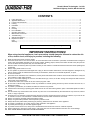
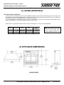
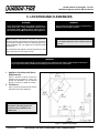
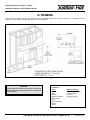
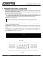
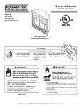
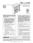
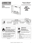
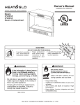
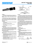
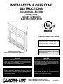
INSTALLATION & OPERATING INSTRUCTIONS VILLAGE COLLECTION QV32E (120V) QV32EV (208V/240V) ELECTRIC FIREPLACES SAVE THESE INSTRUCTIONS Note: Read these instructions completely before beginning installation. Failure to follow them could cause an appliance malfunction resulting in serious injury and/or property damage. CAUTION: (Shown with door front.) Do not expose the appliance to the elements (such as rain, etc.). (Door front not shipped with appliance.) WARNING! WARNING! All electric heaters have hot and arcing or sparking parts inside. Do not use it in areas where gasoline, paint or flammable liquids are or stored. Do not use where the appliance may be exposed to flammable vapors. This appliance is tested and listed for use only with the optional accessories listed in these instructions. Use of optional accessories not specifically tested for this appliance could void the appliance warranty and/ or result in a safety hazard. WARNING! WARNING! Improper installation, adjustment, alteration, service or maintenance can cause injury or property damage. Refer to this manual. For assistance or additional information, consult a qualified installer. Do not modify this appliance. Use it only as described in this manual. Any other use not recommended by the manufacturer may result in fire, electric shock or personal injury and void the warranty. Hearth & Home Technologies - Colville 1445 North Highway, Colville, WA 99114-2124 4030-240 Rev F Hearth & Home Technologies - Colville 1445 North Highway, Colville, WA 99114-2124 CONTENTS A. B. C. D. E. F. G. H. I. J. K. L. M. Listing Approvals ........................................................................................................................................................... 3 Appliance Dimensions ................................................................................................................................................... 3 Location and Clearances ............................................................................................................................................... 4 Framing .......................................................................................................................................................................... 5 Installation ...................................................................................................................................................................... 6 Wiring ............................................................................................................................................................................ 7 Finishing ........................................................................................................................................................................ 9 Final Installation ........................................................................................................................................................... 10 Operating Instructions ................................................................................................................................................. 13 Maintenance Instructions ............................................................................................................................................. 16 Troubleshooting ........................................................................................................................................................... 18 Optional Components .................................................................................................................................................. 19 Replacement Parts ...................................................................................................................................................... 20 Index ............................................................................................................................................................................ 23 Warranty ...................................................................................................................................................................... 24 Note: An arrow (Æ) found in the text and in the index signifies change in content. IMPORTANT INSTRUCTIONS! When using electrical appliances, basic precautions should always be followed to reduce the risk of fire, electric shock, and injury to persons, including the following: 1. 2. 3. 4. 5. 6. 7. 8. 9. 10. 11. 12. 13. 14. 15. 16. 17. 18. 19. 20. 21. 22. Read all instructions before using this heater. This heater is hot when in use. To avoid burns, do not let bare skin touch hot surfaces. If provided, use handles when moving this heater. Keep combustible materials, such as furniture, pillows, bedding, papers, clothes, and curtains at least 3 feet (.9m) from the front of the heater and keep them away from the sides and rear. Extreme caution is necessary when any heater is used by or near children or invalids and whenever the heater is left operating and unattended. Always unplug heater when not in use. Do not operate any heater with a damaged cord or plug or after the heater malfunctions, has been dropped or damaged in any manner. Return heater to authorized service facility for examination, electrical or mechanical adjustment, or repair. Do not use outdoors. This heater is not intended for use in bathrooms, laundry areas and similar indoor locations. Never locate heater where it may fall into a bathtub or other water container. Do not run cord under carpeting. Do not cover cord with throw rugs, runners, or the like. Arrange cord away from traffic area and where it will not be tripped over. To disconnect heater, turn controls to off, then remove plug from outlet. Do not insert or allow foreign objects to enter any ventilation or exhaust opening as this may cause an electric shock or fire, or damage the heater. To prevent a possible fire, do not block air intakes or exhaust in any manner. A heater has hot and arcing or sparking parts inside. Do not use it in areas where gasoline, paint, or flammable liquids are used or stored. Use this heater only as described in this manual. Any other use not recommended by the manufacturer may cause fire, electric shock, or injury to persons. Avoid the use of an extension cord because the extension cord may overheat and cause a risk of fire. However, if you have to use an extension cord, the cord shall be No. 16 AWG minimum size and rated not less than 1875 watts. Always use properly grounded fused and polarized outlets. Always use ground fault protection where required by electrical code. Always disconnect power before performing any cleaning, maintenance or relocation of the appliance. To prevent a possible fire, do not burn wood or other materials in this appliance. To prevent personal injury, do not strike appliance glass. To prevent electric shock or fire, always use a certified electrician should new circuits or outlets be required. When transporting or storing the heater, keep in a dry place free from excessive vibration and store as to avoid damage. SAVE THESE INSTRUCTIONS FOR FUTURE REFERENCE 09/03 4030-240 Rev F VILLAGE COLLECTION ELECTRIC FIREPLACE 2 Hearth & Home Technologies - Colville 1445 North Highway, Colville, WA 99114-2124 A. LISTING APPROVALS U.S. And Canada Certification The QV32E has been tested in accordance with the UL2021 Standards for fixed and location-dedicated electric room heaters in the United States, the current CSA C22.2 NO. 46 in Canada and has been listed by Underwriters Laboratories Inc. for installation as described in this manual. All components are UL or CSA safety certified. If you need assistance during installation, please contact your local dealer or Quadra-Fire Technical Services Department, Hearth & Home Technologies Inc., 1445 North Highway, Colville, WA 99114-2124. Quadra-Fire® is a registered trademark of Hearth & Home Technologies Inc., Division, HON INDUSTRIES. Description QV32E 31" fireplace 120/208/240 1400/2000/2600 12.5/10.8/12.5 QV32EV 31" fireplace Voltage 208/240 Watts Amps (120/208/240) MODEL 2000/2600 10.8/12.5 Note: This equipment has been tested and found to comply with the limits for a Class B digital device, pursuant to Part 15 of the FCC rules. B. APPLIANCE DIMENSIONS QV32E/QV32EV 3 VILLAGE COLLECTION ELECTRIC FIREPLACE 09/03 4030-240 Rev F Hearth & Home Technologies - Colville 1445 North Highway, Colville, WA 99114-2124 C. LOCATION AND CLEARANCES WARNING! WARNING! Due to high temperatures, this appliance should be located out of traffic. Keep combustible materials such as furniture, pillows, bedding, papers, clothes and curtains at least 3 feet (.9M) from the front of the appliance. Never locate this appliance where it may fall into a bathtub or other water container. Note: Minimum and maximum clearances must be main- CAUTION: tained at all times. Illustrations throughout these instructions reflect typical installations and are for design purposes only. Actual installation may vary slightly due to individual design preferences. Do not expose appliance to the elements (such as rain, etc.). The illustrations and diagrams used throughout these installation instructions are not drawn to scale. WARNING! To prevent contact with sagging or loose insulation, the appliance must not be installed against vapor barriers or exposed insulation. Localized overheating could occur and a fire could result. 1. Appliance Locations and Space Requirements Figure 1 illustrates a variety of ways the appliance may be located in a room. The QV32E and QVE32EV may be installed directly on the floor or raised on a hearth. 2. Clearances Figure 1 shows all clearances that must be maintained around the appliance. CAUTION: Wear gloves and safety glasses for protection during installation and maintenance. Figure 1 - Appliance Locations 09/03 4030-240 Rev F VILLAGE COLLECTION ELECTRIC FIREPLACE 4 Hearth & Home Technologies - Colville 1445 North Highway, Colville, WA 99114-2124 D. FRAMING Figure 2 shows a typical framing of this appliance using combustible materials. All required clearances to combustibles must be adhered to. Header height is measured from the base of the appliance. Figure 2 - Framing CAUTION: Provide adequate clearances around the air openings and adequate accessibility clearances for servicing and proper operation. 5 Tools and building supplies normally required for installation: Tools: Saw Pliers Hammer Phillips screwdriver Tape measure Level Electric drill/bits Square Gloves Building Supplies: Wall-finishing materials Framing material Surround Caulking material VILLAGE COLLECTION ELECTRIC FIREPLACE 09/03 4030-240 Rev F Hearth & Home Technologies - Colville 1445 North Highway, Colville, WA 99114-2124 E. INSTALLATION Select a suitable location that is not susceptible to moisture and is away from drapes, furniture and high traffic areas. If installing the appliance on/over carpeting, the appliance must be installed on a wood or metal panel extending the full width and depth of the appliance. Note: Follow all national and local electrical codes. 1. Wall Cabinet Kit, Corner Cabinet Kit or Custom Cabinet Installation *If the power cord is to be used, the Cabinet must provide access to the wall outlet.* a. b. c. d. e. For ease of electrical hookup, you may wish to install the appliance near an existing outlet. A 15 amp, 120 volt circuit is required. A dedicated circuit is preferred but not essential in all cases. A dedicated circuit will be required if, after installation, the circuit trips or fuse blows on a regular basis while the appliance is operating. Additional appliances on the same circuit may exceed the current rating of the circuit breaker. If using a listed wall cabinet or corner cabinet, refer to the installation instructions supplied with the kit. For custom cabinets, frame and construct with the opening and depth dimensions listed in Figures 1 and 2. Before plugging the appliance into the wall outlet, make sure all control switches are in the OFF position. Open the lower grille panel to gain access to the controls. Before finishing the cabinet, the appliance must be set into the cabinet and the power cord routed to the electrical outlet. If the power cord is not being used, refer to Section F. Wiring for hard wiring instructions. If the power cord does not reach the outlet, a No. 16-AWG minimum wire size extension cord rated for a minimum of 1875 watts may be used. To complete the appliance installation, refer to Section H. Final Installation. 2. Non-Cabinet or Chase Installation a. b. c. d. e. Follow recommended framing dimensions in Figures 1 and 2. Set the appliance into the framed opening. Secure the appliance in place by bending out the two nailing flanges on both sides of the appliance and nail to the framing. The nailing flanges have been positioned 5/8 back from the front of the appliance to allow for the addition of drywall. Wiring instructions for 120/208/240V can be found in Section F. Wiring. The power cord must be removed and appliance be hardwired in all non-cabinet or chase installations. Use recommended power supply wire size in accordance to national and local codes. It is recommended to have the appliance on a dedicated service. Remove the protective cover before finishing the front of the appliance. To finish out the appliance, follow the instructions found in Section G. Finishing. To complete appliance installation, see Section H. Final Installation. WARNING - RISK OF FIRE! WARNING - RISK OF FIRE! The power cord must not be pinched or against a sharp edge. Secure cord to avoid tripping or snagging to reduce the risk of fire, electric shock or personal injury. To prevent a possible fire, do not block air intake or exhaust in any manner. Do not use on soft surfaces (like a bed) where openings may become blocked. Do not run cord under carpeting. Do not cover cord with throw rugs, runners or the like. Arrange cord away from traffic areas and where it will not be tripped over. CAUTION: When transporting or storing this appliance and cord, keep in a dry place that is free from excessive vibration. Store so as to avoid damage. 09/03 4030-240 Rev F VILLAGE COLLECTION ELECTRIC FIREPLACE 6 Hearth & Home Technologies - Colville 1445 North Highway, Colville, WA 99114-2124 F. WIRING Note: This appliance must be electrically wired and grounded in accordance with local codes or, in the absence of local codes, with National Electric Code ANSI/NFPA 70-latest edition or the Canadian Electric Code, CSA C2.1 as appropriate. All wiring to be done by a qualified electrician. Use appropriate wire to meet local and national codes for rated power consumption. Note: Optional Accessories Requirements: Wiring for optional accessories should be done now to avoid reconstruction. CAUTION: Label all wires prior to disconnection when servicing controls. Wiring errors can cause improper and dangerous operation. Verify proper operation after servicing. 1. Power Supply Wiring a. b. c. 110/120VAC Wall Outlet Installation 1) The appliance is wired from factory with a polarized plug. 2) For ease of electrical hook up, you may wish to install the appliance near an existing outlet. A 15 amp, 120 volt circuit is required. A dedicated circuit is preferred but not essential in all cases. A dedicated circuit will be required if, after installation, the circuit trips or fuse blows on a regular basis when the appliance is operated. Additional appliances on the same circuit may exceed the current rating of the circuit breaker. 3) Before plugging appliance into wall outlet, make sure all control switches are in the OFF position. To access the controls, lift up on the lower grille panel and rotate it forward. 4) If the power cord is not being used, go to Step 1b below. If the cord does not reach the outlet, a No. 16-AWG minimum wire size extension cord rated for a minimum of 1875 watts may be used. 110/120VAC Hardwire Installation (Minimum 14 gauge two conductor wire, non-metallic sheathing with ground.) 1) Turn off circuit breaker. 2) Remove cover plate located on the right side of appliance. 3) Disconnect black (L1) and white (L2) wires between the appliance and plug. Remove the power cord from the cover plate. Remove the electrical knockout and install the cable clamp (not provided) onto the cover plate. Remove the connectors on the wires from the appliance and strip them back ½. 4) Feed 8 of service wire through cable clamp and secure. 5) Connect black (L1) and white (L2) wires of the appliance to the black and white wires from the service. Connect green (ground) wire from appliance to the ground of the service. See Figure 3. 6) Wall switch wiring (see below) is to be done at this time. 7) Replace the cover plate onto the appliance. 8) Remove the protective cover by cutting the tape located on the outer perimeter and follow Section H. Final Installation on setting up the appliance. HT240V Heater Kit and 208/220/240VAC Hardwire Installation (Minimum 14 gauge three conductor wire, non-metallic sheathing with ground.) 1) Turn off circuit breaker. 2) Remove cover plate located on the right side of appliance. 3) For HT240V installation only, disconnect black (L1) and white (L2) wires between the appliance and plug. Remove the power cord (HT240V only) from the cover plate. 4) Remove the electrical knockout and install the cable clamp onto the cover plate. Remove the connectors on the wires from the appliance and strip them back ½. 5) Feed 8 of service wire through cable clamp (not provided) and secure. 6) Connect black (L1), white (L2) and red (L3) wires of the appliance to the black, white and red wires from the service. Connect green (ground) wire from appliance to the ground of the service. See Figure 4. 7) Wall switch wiring (see below) is to be done at this time. 8) Replace the cover plate onto the appliance. 9) Remove the protective cover by cutting the tape located on the outer perimeter and follow Section H. Final Installation on setting up the appliance. 2. Wall Switch Wiring (24VAC) (hardwired appliances only) a. b. c. 7 *Do not connect wires to 120/208/240VAC* Turn off circuit breaker. Remove cover plate located on the right side of appliance. Feed 8 of wire for the wall switch through the cable clamp and secure. Low voltage wire can be used for the wall switch connection. It is recommended to only go 10 from the appliance to the wall switch. VILLAGE COLLECTION ELECTRIC FIREPLACE 09/03 4030-240 Rev F Hearth & Home Technologies - Colville 1445 North Highway, Colville, WA 99114-2124 d. e. f. Locate the light blue (wall switch) wires in the appliance. Connect one wall switch (blue) wire to wire for switch and connect the other wall switch (blue) wire to the other wire for switch. Replace the cover plate onto the appliance. Run the wall switch wire to the wall box and connect to a wall switch (WSK-21-HTI & WSK-21-W-HTI). WARNING! Always use properly grounded, fused and polarized outlets. Always use ground fault protection where required by electrical code. Figure 3 - 110V/120V Wiring Diagram Figure 4 - 208V/240V Wiring Diagram 09/03 4030-240 Rev F VILLAGE COLLECTION ELECTRIC FIREPLACE 8 Hearth & Home Technologies - Colville 1445 North Highway, Colville, WA 99114-2124 G. FINISHING Combustible Finishing Material Materials made of or surfaced with wood, compressed paper, plant fibers, plastics or any material capable of igniting and burning, whether flame proofed or not, plastered or unplastered (this includes drywall). Noncombustible Finishing Material Materials which will not ignite and burn. Such materials are those consisting entirely of steel, iron, brick, tile, concrete, slate, glass or plasters or combinations thereof, or have a UL Fire rating of Zero (0). WARNING! Grilles on this appliance cannot, in any way, be covered as it may create a fire hazard. Figure 5 - Finishing Materials Note: The remote wall switch (hard wired appliances only) must be wired prior to applying the finishing material in order to avoid reconstruction. Finishing Checklist 1. 2. 3. 4. Power supply service must be either completed or placed within the appliance prior to finishing to avoid reconstruction. Wall switch wires (hardwired appliances only) must also be completed to avoid reconstruction. See Section F. Wiring. Combustible material may cover the black outer surface by ½ on the 110/120v appliances only. See Figures 5-6. Combustible material may not cover the black outer surface on 208/220/240V appliances. See Figure 7. Grilles and air openings cannot be covered in any circumstances. Noncombustible material may cover all black outer surfaces. Grilles and air openings may not be covered. Protective cover may stay on during framing, but removed before final finishing. Once final finishing has been completed, the protective cover can be used to protect appliance until final installation is complete. Figure 6 - Combustible Finishing Material (for 110/120V appliances) 9 Figure 7 - Combustible Finishing Material (for 208/220/240V appliances) VILLAGE COLLECTION ELECTRIC FIREPLACE 09/03 4030-240 Rev F Hearth & Home Technologies - Colville 1445 North Highway, Colville, WA 99114-2124 H. FINAL INSTALLATION Remove the protective cover to access the final installation items. Remove the lava rock and white rock from the inside of the appliance. 1. Remove the Log Assembly Logs are attached to the grate by two zip-ties. Carefully cut both ties by using a utility knife or side cutters. Discard ties and packaging material. Lift the log set straight up and place in a safe place. 2. Remove the Grate Remove the two screws from the grate (one on each side), lift up the grate and set it aside. 3. Install the Side Refractory a. b. c. d. e. f. Remove the refractory and fasteners from the carton. Take the refractory support bracket and bend it until it is L shaped. Install the bracket to the underside of the firebox top using the screws provided. Keep the bracket loose to allow the refractory to slide in behind it. Tilt the side refractory into the appliance and slide it behind the bracket. See Figure 8. Tighten the bracket when the refractory is resting on the hearth and is up against the back glass. Repeat for the other side. Figure 8 Sliding the Side Refractory Behind the Bracket (right side shown) 4. Reinstall the Grate a. b. Put the grate back into the appliance, making sure the middle grate bar is sitting in the back bracket. Replace the screws removed in Step 2. 5. Install the Hearth Refractory a. b. c. d. Place the right hearth refractory into the appliance so the outer edge fits up against the side refractory. See Figure 9. Loosen (if needed) the side refractory bracket to allow the hearth refractory to sit correctly (tight against the side of the firebox). The side refractory will rest upon the hearth refractory. See Figure 10. Tighten the side refractory bracket. Repeat for the other side. Figure 9 - Hearth Refractory Going In (right side shown) Figure 10 - Hearth Refractory In (right side shown) 09/03 4030-240 Rev F VILLAGE COLLECTION ELECTRIC FIREPLACE 10 Hearth & Home Technologies - Colville 1445 North Highway, Colville, WA 99114-2124 6. Install the Andirons a. b. c. d. e. 11 Bend the inner tabs of the andiron clips 90 degrees with a pair of pliers. See Figure 11. Using the bent tab as an anchor, wrap the clip around the front grate bar so the open ends face out of the appliance. See Figure 12. Slide the andiron into the clip. See Figure 13. Repeat for the other side. Position the andirons against the inner grate bar. See Figure 14. Figure 11 Preparing the Andiron Clip Figure 13 Andiron Installed Figure 12 Wrapping the Clip Around the Grate Figure 14 Positioning the Andirons VILLAGE COLLECTION ELECTRIC FIREPLACE 09/03 4030-240 Rev F Hearth & Home Technologies - Colville 1445 North Highway, Colville, WA 99114-2124 7. Place the White Rock Open the bag of white rock and spread it over the ember bed glass and hearth refractory (if desired). This will create the effect of burning embers. Not all of the white rock needs to be used. See Figure 15. 8. Place the Lava Rock Open the bag of lava rock (black) and spread it sparingly on top of the white rock and hearth refractory. This will create the effect of an ash bed. Not all of the lava rock needs to be used. See Figure 16. 9. Replace the Log Assembly Set the logs back onto the grate assembly. Some of the rock may have to be rearranged. This will allow the logs to set correctly on the grate. See Figure 17. 10. Install the Door Front a. b. Remove the door front and hood from the packaging. Using pliers (or your hands), bend out the tabs on the columns to attach the front to the appliance. See Figure 18. Follow the installation instructions included in the door front kit. Figure 16 - Placing Lava Rock The appliance is now ready to operate. See section I. Operating Instructions. Note: When placing the white rock and lava rock, you may want to periodically turn on the appliance to check the appearance and customize to the desired effect. Figure 17 - Replace Log Assembly Figure 15 - Placing White Rock Figure 18 - Bending Out Tabs 09/03 4030-240 Rev F VILLAGE COLLECTION ELECTRIC FIREPLACE 12 Hearth & Home Technologies - Colville 1445 North Highway, Colville, WA 99114-2124 I. OPERATING INSTRUCTIONS WARNING! All electric heaters have hot and arcing or sparking parts inside. Do not use it in areas where gasoline, paint or flammable liquids are or stored. Do not use where the appliance may be exposed to flammable vapors. 1. Manual Controls a. Access Controls Controls are located behind the lower grille panel. To access the controls, lift up on the lower grille panel and rotate it forward. b. Function of Manual Controls 1) Main Power Switch a) Main power switch is used to provide power to all controls. When the main power switch is on, the appliance can be turned on by one of three methods: by the manual control on the appliance, the remote control (optional) and/or the wall switch (optional). Also, when the main power switch in the ON position, you will be able to operate the auxiliary switch. b) When the main power switch is off, the manual switches, remote control and wall switch will not work. c) It is recommended that during long periods of non-usage that the main power switch is turned to the OFF position. 2) Flame Switch a) When the flame switch is in the ON position, the lights and flame will come on. b) The flame switch must also be in the ON position before the heater system will turn on. c) When the flame switch is in the OFF position, the remote control or the wall switch can be used to turn the appliance on and off. Note: If you lose power during operation or by turning the main power switch to OFF, the appliance will need to be reset. To reset the appliance, make sure that you have power to the appliance and the main power switch is in the ON position. Turn the flame switch off and on to reset the appliance. 3) 4) 5) 6) 7) 13 Flame/Ember Bed Intensity Control To change the intensity of the flame and ember bed, turn the control knob clockwise to increase the intensity. Turn the control knob counter-clockwise to reduce the intensity. Flame/Ember Bed Motion Control To change the motion of the flame and ember bed, turn the control knob clockwise to increase the motion. Turn the control knob counter-clockwise to reduce the motion. Heater Switch a) The heater will only operate if the flame switch is in the ON position. With the flame switch on, the heater system is supplied with power and is able to be turned on. b) When the heater is in the OFF position, the appliance can operate with flame but no heat. Thermostat Control a) With the heater system on, the thermostat control will allow you to adjust the temperature to the desired setting. b) To adjust the thermostat to the desired temperature setting, turn the control knob clockwise all the way. Then turn counter-clockwise until you hear a click. c) If this is not the desired temperature setting, turn the control knob clockwise slightly. You should hear a click and the heater should be on. You may have to adjust the thermostat once the desired room temperature is reached and the heater system is still on. d) To increase the desired temperature setting, turn the control knob clockwise until you hear a click and the heater system will turn on. Auxiliary Switch (not used) VILLAGE COLLECTION ELECTRIC FIREPLACE 09/03 4030-240 Rev F Hearth & Home Technologies - Colville 1445 North Highway, Colville, WA 99114-2124 2. Hand Held Remote Control Transmitter - RCE-QUAD (Optional) a. b. c. d. The RCE-QUAD is an optional accessory listed with the QV32E and QV32EV. The transmitter is a radio frequency remote control. The frequency can be found on the back side of the transmitter. The range of the transmitter is approximately 20 from appliance. When the remote LED light is RED, the appliance has been turned on/off by the remote transmitter. The manual controls located on the dashboard will override any other external controls (remote control/wall switch) used to operate the appliance. Hand Held Remote Transmitter/Appliance Initialization 1) The transmitter operates on a 12V battery (included) made specifically for remote controls and electronic lighters. Install the 12V battery supplied with the appliance into the battery compartment of the hand held remote transmitter. It is recommended that alkaline batteries always be used for longer battery life and maximum operational performance. If the signal light does not illuminate (when it normally would), check the position of the transmitters battery. 2) Initialization only has to be done once. Note: If you lose power during operation or by turning the main power switch to OFF, the appliance will need to be reset. To reset the appliance, make sure that you have power to the appliance and the main power switch is in the ON position. Turn the flame switch off and on to reset the appliance. 3) 4) 5) 6) 7) 8) Turn the main power switch on and then turn the flame switch on. Locate the LEARN button on the dashboard. The LEARN button is located behind the lower grille/panel. To push the button, use a blunt object (such as a pencil). Push the button in and release. The remote LED light should blink green. The remote LED light is located above the main power switch. Push and hold either the on or off button on the hand held remote transmitter. The remote LED light should begin to blink rapidly. Release the button on the hand held remote transmitter and the remote LED light should stop blinking green and go out. This indicates that the transmitter and appliance are initialized. If the remote LED light turns red, the hand held remote transmitter is active. The hand held remote transmitter is ready to be used. WARNING! Changes or modifications to this device not expressly approved by the party responsible for compliance could void the users authority to operate the equipment. 09/03 4030-240 Rev F VILLAGE COLLECTION ELECTRIC FIREPLACE 14 Hearth & Home Technologies - Colville 1445 North Highway, Colville, WA 99114-2124 e. Remote Transmitter Function 1) The hand held remote transmitter is only an on/off control. When the transmitter is active, the remote LED light will be RED. Upon initial use, there may be a delay of three seconds before the remote receiver will respond to the transmitter. This is part of the systems design. 2) With the main power switch (located on the appliance) in the ON position, press the on button on the hand held remote transmitter to turn on the appliance. The transmitter does not control/change the other switches or controls located on the appliance. Features of the appliance (flame motion and heater) will remain in their last set position. If you would like to change the setting you will have to access the manual controls (located on the appliance) to set the desired position. 3) To turn off the appliance, press the OFF button on the hand held remote transmitter. 4) With the appliance turned on by the hand held remote transmitter, you can override it by turning the manual flame switch on the appliance to OFF or by turning the optional wall switch off. 5) Operation of the switches on the dashboard will override all other switches within the appliance system and be operated by the dashboard switches. 3. Wall Switch Control (hardwired appliances only) (WSK-21-HTI & WSK-21-W-HTI) a. b. c. d. The wall switch wiring can be found in the Section F. Wiring. The wall switch has an operating voltage of 24VAC, do not hook up to 120/208/240VAC. For installations you can use 24AWG thermostat wire connected to a standard wall switch. It is recommended not to exceed 15 of wire from appliance. With the main power switch (located on the appliance) in the ON position, the wall switch can turn the appliance on and off. The wall switch does not control the other switches or controls located on the appliance. Features of the appliance (flame motion and heater) will remain in their last set position. If you would like to change the setting, you will have to access the manual controls (located on the appliance) to set the desired position. With the appliance turned on by the wall switch, you can override it by turning the manual flame switch on the appliance to OFF or by pressing the OFF button on the remote transmitter. 4. FCC Requirements If this equipment does cause harmful interference to radio or television reception, which can be determined by turning the equipment off and on, the user is encouraged to try to correct the interference by one or more of the following measures: Reorient or relocate the receiving antenna. Increase the separation between the equipment and the receiver. Connect the equipment into an outlet on a circuit different from that to which the receiver is connected. Consult the dealer or an experienced radio or TV technician for help. CANADIAN EQUIPMENT REQUIREMENTS This digital apparatus does not exceed the Class A/Class B limits for radio noise emissions from digital apparatus set out in the Radio Interference Regulations of the Canadian Department of Communications. This device complies with RSS-210 of Industry and Science Canada. Operation is subject to the following two conditions: 1) This device may not cause interference, and 2) this device must accept any interference, including interference that may cause undesired operation of the device. Note: This equipment has been tested and found to comply with the limits for a Class B digital device, pursuant to Part 15 of the FCC rules. These limits are designed to provide reasonable protection against harmful interference in a residential installation. This equipment generates, uses and can radiate radio frequency energy, and, if not installed and used in accordance with the instructions, may cause harmful interference to radio communications. However, there is no guarantee that interference will not occur in a particular installation. 15 VILLAGE COLLECTION ELECTRIC FIREPLACE 09/03 4030-240 Rev F Hearth & Home Technologies - Colville 1445 North Highway, Colville, WA 99114-2124 J. MAINTENANCE INSTRUCTIONS WARNING! Always disconnect power and allow the appliance to cool before performing any cleaning, maintenance or relocation of this appliance. Turn controls to OFF and remove the plug from the outlet or turn off the circuit breaker to the appliance. 1. Cleaning the Firebox and Control Compartment Keep the firebox, control compartment and heater system clean. Clean by brushing and vacuuming at least once a year. To access the control compartment, follow the instructions for replacing the light bulbs. Follow the heater maintenance instructions to access the heater system. Failure to do this may shorten the fans life. Always disconnect power before performing any cleaning or maintenance. 2. Cleaning the Glass Doors & Back Glass The glass is cleaned in the factory during the assembly process. During shipment, installation, handling, etc., the glass surface may collect dust particles. These can be removed by buffing lightly with a clean dry cloth. To remove fingerprints or other marks, the glass can be cleaned with a damp cloth using a good quality household glass cleaner. The glass should be completely dried with a lint free cloth or paper towel. In the event of glass breakage, vacuum all remaining glass pieces with a shop vac. DO NOT VACUUM IF PIECES ARE HOT! Replace glass only with a glass panel ordered direct or through your local distributor. Never use substitute material. Only fully tempered soda lime safety glass may be used on this appliance. Safety Note: 3. Replacing the Light Bulbs The light bulbs will need to be replaced when the flame and/or ember bed is dark on one side. Replace the bulbs with 75 watt halogen bulbs with minicandelabra base. Do not exceed 75 watts per bulb. Light bulbs can be purchased at local hardware, lighting stores, online or by phone. To order online, log onto www.lite-house.com or call 1-800-838-0977. Sylvania model 75Q/CL/MC/RP or Satco model S3157 are recommended. Handle glass with care to avoid striking, scratching or slamming shut. NEVER clean glass when hot. Keep children and pets a safe distance away. WARNING! To avoid accidental burning of the skin, allow at least five minutes for the light bulbs to cool before touching them. a. Figure 19 Replacing the Bulbs 09/03 4030-240 Rev F Turn off the circuit breaker or unplug the appliance before replacing the light bulbs. b. Open the lower grille panel to view the dashboard on the appliance (the lower grille may need to be removed). c. Remove the four outer screws. See Figure 19. d. Pull dashboard towards you to expose the light compartment (the light compartment does not need to be pulled all of the way out of the appliance). e. Carefully remove burned out bulb from light socket. Place new bulb in socket. Follow directions on light bulb package for handling requirements. f. Slide dashboard back into appliance and make sure all wires are inside appliance. g. Reinstall the four screws removed earlier. h. Turn ON circuit breaker or plug appliance back into wall outlet. VILLAGE COLLECTION ELECTRIC FIREPLACE 16 Hearth & Home Technologies - Colville 1445 North Highway, Colville, WA 99114-2124 CAUTION: Although the glass is safety glass, it may break if dropped, bumped or struck. Care must be taken when handling the glass. 4. Heater System Maintenance a. b. c. d. e. f. g. h. i. j. k. Turn off the circuit breaker/unplug the appliance before servicing the heater system. Allow appliance to cool before removing. Remove the hood by pulling it straight out. Remove the upper panel/door front by lifting it up and out. Remove the four outer screws. See Figure 20. Pull the heater system out of appliance. With the heater system out of the appliance, reach into the back of the appliance and unplug wire harness from connector. To remove plug squeeze both sides and pull. Slide the heater system back into the appliance, making sure that the wires do not touch the heater housing. If the heater system is not locked on the clip the front will not be flush. Once the front of the heater system is flush with appliance, reinstall the four screws removed earlier. Replace the upper panel and hood. Turn on circuit breaker when heater installation is complete. Follow the operating instructions found in section I. Operating Instructions. 2019 Installing the Heater 17 VILLAGE COLLECTION ELECTRIC FIREPLACE 09/03 4030-240 Rev F Hearth & Home Technologies - Colville 1445 North Highway, Colville, WA 99114-2124 K. TROUBLESHOOTING Issues Possible Causes Solutions: Appliance doesn't turn on with flame switch, remote transmitter or wall switch. 1. 2. Main power switch is off. Circuit breaker tripped. 1. 2. 3. 4. Unplugged from wall outlet. Loose wiring. 3. 4. Appliance is on but no flame or low flame intensity. 1. 2. The bulbs are burned out. Loose wiring. 1. 2. Replace the bulbs. Check all wiring for loose connections. Flames are frozen. 1. 2. 3. Loose wiring. Flame element is not attached to motor. Motor is defective. 1. 2. 3. Check all wiring for loose connections. Reattach the flame element to the motor. Replace the motor. Excessive noise in lower portion of the appliance. 1. 2. Flame element isn't seated properly. Motor is defective. 1. 2. Reinstall the flame element. Replace the motor. Turn the heater switch on or off and the appliance shuts off. Heater doesn't come on. Operating the heater's system defaults to the flame switch setting. 1. 2. 3. Heater switch is off. Thermostat is set too low. Heater system is overheated. Loose wiring. 4. Turn the main power switch to the "ON" position. May need to put the appliance on a dedicated service or reduce the number of appliances on the ciruit. Plug cord into outlet. Check all wiring for loose connections. Turn the flame switch, remote transmitter or wall switch to the "ON" position. 1. 2. 3. 4. Turn heater switch on. Turn the thermostat knob clockwise until you hear a "click". The heater is protected by a thermal cutout switch. Shut OFF all appliance switches on the dashboard, including the main power switch. Wait 5 minutes, then turn the appliance ON. Check all wiring for loose connections. Fan runs but no heat is put out. 1. 2. Loose wiring. Bad heating element. 1. 2. Check all wiring for loose connections. Replace the heating system. Heater element is on but fan doesn't run. 1. 2. Loose wiring. Fan is defective. 1. 2. Check all wiring for loose connections. Replace the heating system. The heater doesn't turn off. Thermostat is set too high. Turn the thermostat knob counter-clockwise until you hear a "click". Excessive noise in upper portion of the appliance. 1. 2. Build up of dirt on the fans. Heater fan is defective. 1. 2. Clean all fans. Replace the heater system. Remote control doesn't work. 1. 2. 3. 4. Main power switch is off. Remote is out of range. Low batteries. Lost initialization. 1. 2. 3. 4. Turn the main power switch on. Move remote closer to the appliance. Replace the batteries. Reinitialize remote. Wall switch doesn't work. 1. 2. 3. Main power switch is off. Loose wiring. Wall switch is defective. 1. 2. 3. Turn the main power switch on. Check all wiring for loose connections. Replace the wall switch. Odor 09/03 4030-240 Rev F The heater may emit a slight, harmless odor when first used. This is a normal condition caused by initial heating of the internal parts and will not occur again. VILLAGE COLLECTION ELECTRIC FIREPLACE 18 Hearth & Home Technologies - Colville 1445 North Highway, Colville, WA 99114-2124 L. OPTIONAL COMPONENTS Front Faces Part # Description Finish Part # Description Finish DF-32RA-HP Remi ngton Avenue Hammered Pewter DF-32CH-HP Chapel Hi ll Hammered Pewter DF-32RA-BK Remi ngton Avenue Black DF-32CH-BK Chapel Hi ll Black DF-32TS-HP Town Square Hammered Pewter DF-32HH-BK Harmony Hall Black DF-32TS-BK Town Square Black DF-32SPO-BK Sun Prai ri e Operable Door Black DF-32SP-HP Sun Prari e Hammered Pewter DF-32SPO-HP Sun Prai ri e Operable Door Hammered Pewter DF-32SP-BK Sun Prari e Black DF-32CH-HP DF-32CH-BK Front Face Cabinets RCE - QUAD Remote Control Wall Cabinets QV32E Depth (moulding not included) Suffix Corner Cabinets ROA44DB * A MVA44DB * 18" * O = Unstained Oak * P = Primed P LA 44D B * ROC44SB * MVC44SB * WSK-21-HTI WSK-21-W-HTI Wall Switch Kit SB P LC 44S B * (258mm) HT240V 240V Heater Kit * O = Unstained Oak * P = Primed (QV32E only) Surrounds & Trim Flush Surrounds (chase installations only) ROF44SB * MVF44SB * P LF 44S B * * O = Unstained Oak * P = Primed 19 VTS-550 (Polished Brass Finish) VTS-550-BK (Black Finish) Quick Tile Black and Brass Surround PBT-550 (Polished Brass Finish) BKT-550 (Black Finish) Cabinet Trim VILLAGE COLLECTION ELECTRIC FIREPLACE 09/03 4030-240 Rev F Hearth & Home Technologies - Colville 1445 North Highway, Colville, WA 99114-2124 M. REPLACEMENT PARTS Replacement parts are available from your distributor/dealer. (Hood supplied with door front kit.) 09/03 4030-240 Rev F VILLAGE COLLECTION ELECTRIC FIREPLACE 20 Hearth & Home Technologies - Colville 1445 North Highway, Colville, WA 99114-2124 1 - Log Set Refractories Item # Part # Description Qty. 1 4030-055 Log Assembly 1 2 4030-803 Ember Bed Glass 1 3 4030-817 Back Glass 1 4 4030-811 Ember Rock (not shown) 1 5 23509 Lava Rock (not shown) 1 6 Æ 21 Halogen Bulbs (see Maintenance instructions) 2 7 4030-043 4030-049 Heater Assembly - 120VAC Heater Assembly - 240VAC (not shown) 1 8 4030-046 Screen Assembly (not shown) 1 9 4030-150 Dashboard Assembly 1 10 4030-060 Motor - 12VDC 1 11 4030-840 Flame 1 12 047-805 13 4030-802 Power Cord - QV32E 1 14 4035-107 Flame Element 1 15 4030-029 Grate 1 16 4030-831 Herringbone Side Refractory - left 1 17 4030-832 Herringbone Side Refractory - right 1 18 4030-833 Herringbone Hearth Refractory - left 1 19 4030-834 Herringbone Hearth Refractory - right 1 20 80784 Andiron 2 21 4030-810 22 31120 23 4030-884 Hood Clip (not shown) (not shown) Heat Shrink 2 1 Guide Pin Sleeve (for motor) (not shown) 2 #5x¾" PPH SMS (not shown) 2 VILLAGE COLLECTION ELECTRIC FIREPLACE 09/03 4030-240 Rev F Hearth & Home Technologies - Colville 1445 North Highway, Colville, WA 99114-2124 Home Owners Notes 09/03 4030-240 Rev F VILLAGE COLLECTION ELECTRIC FIREPLACE 22 Hearth & Home Technologies - Colville 1445 North Highway, Colville, WA 99114-2124 Index Symbols L 110/120VAC Wiring 7 110V/120V Wiring Diagram 8 208/220/240VAC Wiring 7 208V/240V Wiring Diagram 8 Lava Rock 12 Light Bulbs 16 Locations 4 Log Set 21 Logs 10, 21 A M Access Controls 7, 13 Appliance Locations 4 Auxiliary Switch 13 Mantel 5 Manual Controls 13 Motion Control 13 B N Back Glass 16 Non-Cabinet Installation 6 Noncombustible Finishing Material 9 C Cabinet Installation Corner Kit 6 Custom 6 Wall Kit 6 Cabinets 19 Certification 3 Chase Installation 6 Cleaning 16 Clearances 2, 4 Codes Electric 3, 7 Combustible Finishing Material 9 Controls 13 Access 7, 13 Functions 13 D Dimensions 3 Doors 16 E Electric Codes 3, 7 Extension Cord 2, 6, 7 F FCC 3, 15 Finishing Checklist 9 Finishing Materials 9 Flame Switch 13 Framing 5 Front Faces 19 G Glass Doors 16 H Hardwiring 7 Heater 13, 17, 19 Heater Switch 13 I Installation Corner Cabinet Kit 6 Custom Cabinet 6 In a Chase 6 Non-Cabinet 6 Wall Cabinet Kit 6 Intensity Control 13 23 O Optional Accessories 1 Optional Components 19 P Power Supply 7 Power Switch 13 R Æ Refractories 21 Refractory 10, 21 Remote Control 14, 19 Remove the Log Assembly 10 Replace the Log Assembly 12 Replacement Parts 20, 21 Replacing the Light Bulbs 16 S Space Requirements 4 Surrounds & Trim 19 T Thermostat 13 Thermostat Control 13 Troubleshooting 18 U UL2021 3 W Wall Cabinet Kit Installation 6 Wall Outlet 7 Wall Switch 7, 15, 19 White Rock 12 Wiring 7 120VAC 7 208VAC 7 240VAC 7 Power Supply 7 Wall Switch 7 Wiring Diagram 120V 8 240V 8 VILLAGE COLLECTION ELECTRIC FIREPLACE 09/03 4030-240 Rev F WARRANTY Hearth & Home Technologies Inc. (HHT) Electric Fireplaces are tested and inspected prior to shipment and are guaranteed from defect to the purchaser of each new product. Any part which proves to be defective in material or workmanship under normal use within one year will be repaired or replaced without charge.* The Company will not be responsible for any expense incurred for installation, removal from service, or transportation costs. Any such defect should be brought to the attention of the Dealer where the product was purchased and is authorized to repair or replace within the terms of this warranty. The Companys only obligation under this warranty will be at its sole option to repair or replace any part proving defective or to refund the purchase price thereof. The owner/user assumes all other risks, if any, including the risk of any direct, indirect or consequential loss or damage arising out of the use of or inability to use the product. The warranty will not apply if, in the sole judgement of the Company, damage or failure has resulted from accident, alteration, misuse, abuse, incorrect installation, or operation on an incorrect power source. The foregoing is in lieu of all other warranties expressed, implied, or statutory, and the Company neither assumes, nor authorizes any person to assume for it any other obligation, or liability in connection with said product. *Light bulbs are not covered in the warranty. How to Obtain Service. To obtain service under this warranty you must: 1. Send written notice of the claimed condition to Quadra-Fire Technical Services Department, Hearth & Home Technologies 2. 3. 4. Inc., 1445 North Highway, Colville, WA 99114-2124. Provide proof of purchase, model number, serial number, and manufacturing date code to HHT. Provide HHT reasonable opportunity to investigate the claim, including reasonable opportunity to inspect the Appliance prior to any repair or replacement work and before the Appliance or any component of the Appliance has been removed from the place of original installation. Obtain HHTs consent to any warranty work before the work is done. ADDITIONAL INFORMATION. If you would like information on current Quadra-Fire products or want to locate a dealer in your area, call 1-800-234-2508. ã2003 Quadra-Fire® is a registered trademark of Hearth & Home Technologies Inc., Division, HON INDUSTRIES. 09/03 4030-240 Rev F VILLAGE COLLECTION ELECTRIC FIREPLACE 24