1
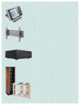
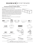
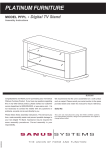
Assembly Instructions for Model: CFAR47
Thank you for choosing the Component Furniture line from Sanus Systems! Use
this manual to configure the CFAR47 as shown on the right. The CFAR47 is designed to hold a LCD, Plasma or DLP TV.
Safety Warning: If you do not understand these directions, or have any doubts
about the safety of the installation, please call a qualified contractor or contact Sanus at 800.359.5520 or www.sanus.com. Check carefully to make sure that there
are no missing or defective parts. Our customer service representatives can quickly
assist you with installation questions and missing or damaged parts. Replacement
parts for products purchased through authorized dealers will be shipped directly to
you. Never use defective parts. Improper installation may cause damage or serious
injury. Do not use this product for any purpose that is not explicitly specified by
Sanus Systems. Sanus Systems can not be liable for damage or injury caused by
incorrect assembly, or incorrect use. Please call Sanus Systems before returning
products to the point of purchase.
Required Tools: Drill, 3/16” drill bit, phillips screw driver, flat head screw driver, crescent wrench, tape measure.
Supplied Parts and Hardware: Hardware shown at actual size. Some
parts may come pre-assembled**
(4) Carpet Spike - a
(12) Cam Pin - b
(8) Spacer - c
(2) Phillips Pan Head Bolt - e
(4) Dowel - f
(4) Glass Shelf Pin - g
(8) Wood Shelf Pin - h (8) Hinge Plate Screw - k**
(16) Hinge Screw - l
(4) Wood Screw - i
(4) Knob Bolt - j**
(2) Tip Protector Bolt - m
(2) Stop Nut - n
(2) Lag Bolt - p
(2) Lag Bolt Washer - q
(8) Back Panel Bolt - d
(8) Hinge Car Bolt - o
(1) Allen Key - r
Sanus Systems 2221 Hwy 36 West. St. Paul, MN 55113 10.10.05
Customer Service: 800.359.5520. See complementary Sanus products at www.sanus.com
Parts: Not all parts shown at the same scale
(4) Foot - s
(4) Door Knob - t**
(4) Hinge Plate - x** (4) Bi-fold Hinge - y
(1) Shelf Retainer - u
(4) Hinge Car - z
(3) Front Rail - cc
(1) Shelf Bracket - v
(4) Small Door Hinge - w
(2) Furniture Bracket - aa
(2) Wall Bracket - bb
(3) Back Rail - dd
(2) Bi-fold Door - gg
(2) Side Panel - ee
(2) Back Panel - ff
(1) Top - ii
(1) Glass Shelf - jj
(2) Wood Shelf - kk
(2) Door - hh
Step 1: Add Wood Shelf Pins and Feet to Side Panels
Insert a Wood Shelf Pin (h) into the holes adjacent to the two lower sets of cams in each Side Panel (ee). See Detailed View A of Diagram
1 for assistance.
Add a Foot (s) to each pillar of the Side Panel (ee). If you wish to install the Carpet Spikes (a), thread each Carpet Spike into the Foot.
You can adjust the height of the Carpet Spikes with the Nut. See Detailed View B of Diagram 1 for assistance.
Warning: The ends of the carpet spikes are very sharp and may scratch floors or furniture. All sharp objects can be
hazardous to children. For this reason we provide the carpet spikes as an option. Sanus Systems will not be liable
for damage or injury.
Detailed View A
ee
h
Detailed View B
s
a
Diagram 1
Step 2: Add Front and Back Rails
Add Front Rails - Attach the Front Rail (cc) to the Side Panel Assembly (ee) by sliding the clamp down the groove in each Side Panel
pillar as shown in the Top View of Diagram 2. Make sure the smooth side of the Front Rail is facing outward and the open channel faces
down as seen in the Detailed View below on the right. Once the Front Rail is positioned at the bottom of the groove and resting on the
Foot (s), tighten the allen bolt on the back side of the Front Rail so the clamp widens to hold the Front Rail firmly in place. Repeat process for the second Front Rail, making sure it is below the upper Wood Shelf Pins (h).
Add Back Rails - To attach the Cam Pins (b) to the Back Rail (dd), make sure the arrow on each Cam is facing the hole in the outside
of the Back Rail and add two Cam Pins to each end of the Back Rail as shown in Diagram 2. Make sure there is a small space between
the head of the pin and the Back Rail as seen in the Detailed View on the right.
Attach the Back Rail by sliding the cam pins down the groove on the Side Panel pillar as shown in the Top View of Diagram 2. Make
sure the Back Rails are oriented so the threaded holes in the center are on the top, and the Cams face inside the cabinet. Once the bottom
Back Rail is resting on the Foot (s), tighten the cams labeled in Diagram 2 to hold it in place. Slide the other Back Rail down the groove
in the pillar in the same manner until it just below the upper Wood Shelf Pins (h). Tighten the cams in a clockwise direction to hold the
back rail in place.
Note: The second Front and Back Rails will need to be adjusted once the upper Wood Shelf is in place.
Detailed View
Top View (Back Rail)
Back Left Corner Diagram 2
b
dd
cams
Detailed View
Top View (Front Rail)
Front Left Corner
allen bolt
clamp
cc
b
clamp
open
channel
Step 3: Prepare TV Shelf
Insert two Wood Screws (i) through the Shelf Bracket (v) and into the underside of the Wood Shelf (kk). Tighten each Wood Screw with
a phillips screw driver. See Diagram 3 for assistance.
Diagram 3
i
kk
v
Step 4: Add Wood Shelves
Press fit the Wood Shelves (kk) so they lock into the Wood Shelf Pins (h).
Once each shelf is secured, loosen the allen bolts on the backside of the upper Front Rail (cc) and raise it until it is level with the upper
Wood Shelf. Tighten each allen bolt on the backside of the Front Rail until secure. Loosen the cams on the Back Rail (dd) and raise it
until it is level with the upper Wood Shelf. Retighten the cams to secure the Back Rail. See Diagram 4 for assistance.
Diagram 4
Detailed View
kk
h
Step 5: Secure upper Wood Shelf
Secure the Shelf Retainer (u) to the upper Wood Shelf (kk) by inserting a Wood Screw (i) through the Shelf Retainer and thread it into
the Wood Shelf. Secure the Shelf Bracket (v) to the upper Back Rail (dd) by threading a Phillips Pan Head Bolt (e) through the Shelf
Bracket and into the Back Rail (dd). See Diagram 5 for assistance.
Detailed View A
Diagram 5
v
dd
e
Detailed View B
u
i
Step 6: Add Hinge Cars
Add the Hinge Cars (z) by sliding them down the groove in the pillar of the Side Panel (ee). Make sure the widest part of the Hinge Cars
is facing the outside of the assembly. See Diagram 6 for assistance.
Diagram 6
Detailed View
z
ee
Step 7: Add Front and Back Rail
Add Front Rail - Attach the Front Rail (cc) to the Side Panel (ee) by sliding the clamp down the groove in each Side Panel pillar as
shown in the Top View of Diagram 7. Make sure the smooth side of the Front Rail is facing outward and the open channel faces down.
Once the Top of the Front Rail is level with the Side Panel, tighten the allen bolt on the back side of the Front Rail so the clamp widens
to hold the Front Rail firmly in place.
Add Back Rail - To attach the Cam Pins (b) to the Back Rail (dd), make sure the arrow on each Cam is facing the hole in the outside
of the Back Rail and add two Cam Pins to each end of the Back Rail as shown in Diagram 7. Make sure there is a small space between
the head of the pin and the Back Rail.
Attach the Back Rail by sliding the cam pins down the groove in the pillar of the Side Panel (ee) as shown in the Top View of Diagram
7. Make sure the Back Rail is oriented so the threaded holes in the center are on the bottom, (Note: this is upside down from the previous
2 Back Rails) and the Cams face inside the cabinet. Once the top of the Back Rail is level with the Side Panel, tighten the cams labeled
in Diagram 7 to hold it in place. Detailed View
Diagram 7
Top View (Back Rail)
Back Left Corner cams
b
Detailed View
dd
Top View (Front Rail)
Front Left Corner
b
allen bolt
clamp
cc
clamp
open
channel
Step 8: Add Back Panels
Add Back Panels (ff) to the assembly by inserting a Back Panel Bolt (d) through each hole in the Back Panels, a Spacer (c) and thread it
into the inserts in the Back Rail (dd). Before tightening the Back Panel Bolts, insert the Furniture Bracket (aa) under the Back Rail. Once
the Back Panels are secured, the Furniture Brackets will be held in place. See Diagram 8 for assistance.
Diagram 8
d
ff
dd
c
aa
Sanus recommends installing the Furniture and Wall Brackets in all applications. Find the location of a stud behind
where the armoire will sit so you can place the Furniture Bracket in the appropriate place.
Step 9: Add Top
Insert a Dowel (f) into each hole in the bottom side of the Top (ii). Add Top so each Dowel is secured in the corner pillar in the Side Assembly (ee). See Diagram 9 for assistance.
Diagram 9
Detailed View
ii
f
Step 10: Add Glass Shelf
Add Glass Shelf Pins (g) to the desired locations into the Side Panel (ee) in the lower portion of the armoire. Insert the Glass Shelf (jj)
into the assembly so it rests on the Glass Shelf Pins. See Diagram 10 for assistance.
Warning: Do not use the Glass Shelf to support a television!
Detailed View
ee
jj
g
Diagram 10
Step 11: Add Hinges and Knobs
Add Hinges (w,y) to the Doors (gg,hh) by inserting a Hinge Screw (l) through the Hinge and into the Door. Tighten each with a phillips
screw driver.
Attach the Door Knobs (t) by inserting a Knob Bolt (j) through the Door (gg,hh) and into the Door Knob. Tighten each with a phillips
screw driver. Repeat process until all Hinges and Door Knobs are secured. See the Detailed Views of Diagram 11 below for assistance.
Detailed View A
Detailed View B
gg
gg
j
y
Diagram 11
l
Detailed View C
t
Detailed View D
hh
hh
j
w
l
t
Step 12: Add Hinge Plates and Small Doors
Add the Hinge Plates (x) by inserting a Hinge Plate Screw (k) through the Hinge Plate, and into the holes in the Side Panel (ee). Tighten
each with a phillips screw driver. Repeat the process for all four Hinge Plates. See Diagram 12 for assistance.
To attach each Hinge (w) to its Hinge Plate (x), the bolt along the back center of the Hinge Plate must be loose during installation. The
slot on the end of the Hinge will fit around the bolt on the Hinge Plate. The top and bottom Hinges should engage at the same time.
Once the two parts of the Hinge are mated, tighten the bolt on the Hinge Plate firmly with a phillips screw driver. See Diagram 12 for
assistance.
Detailed View
Diagram 12
w
ee
x
k
Step 13: Add Bi-fold Doors
Insert a Hinge Car Bolt (o) through each hole in the Bi-fold Hinge (y) and thread it into the Hinge Car (z). Tighten each Hinge Car Bolt
with a phillips screw driver. Repeat Process until each Hinge is secured to the Hinge Car.
Note: The Pillar is shown transparent in the Detailed View of Diagram 13 so you can see the Hinge Car.
Hint: This step will require 2 people.
Detailed View
z
o
y
Diagram 13
Step 14: Secure Wall Bracket to wall
Locate two wood studs using a stud finder. It is a good idea to verify where the stud is with a awl or a thin nail. Mark the location of each
stud. To find the height, measure 54 inches up from the floor. Mark the location on the stud. Drill a 2.5” deep hole with a 3/16” drill bit
at each marked location. Insert a Lag Bolt (p) through a Lag Bolt Washer (q), a Wall Bracket and drive it into the pre-drilled hole until
secured into the stud. The Wall Brackets can be positioned either as shown on the left or the right in Diagram 14 to help account for slight
measurement discrepancies. See Diagram 14 for assistance.
Diagram 14
q
p
wall stud
bb
Step 15: Secure Assembly to wall
Secure the Furniture Brackets (aa) to the Wall Brackets (bb) by inserting a Tip Protector Bolt (m) through both Brackets and into a Stop
Nut (n). Tighten the Stop Nut with a crescent wrench until secure. See the Detailed View of Diagram 15 for assistance.
Note: Diagram 15 is a cutaway view.
Detailed View
aa
n
m
bb
Diagram 15
Step 16: Hinge Adjustment for small Door
Each hinge Assembly is adjustable in multiple directions. See Diagram 16 for assistance.
Diagram 16
Side Adjustment
Depth Adjustment
Height Adjustment
Step 17: Hinge Adjustment for Bi-fold Door
To adjust the Bi-fold Hinges (y), loosen the screws labeled in the Diagrams below for the specified movement.
Note: For height adjustment, loosen the Hinge Car Bolts (o) and slide the Hinge Cars (z) in the track until desired
adjustment is complete.
Side Adjustment
adjustment
point
Depth Adjustment
adjustment
point
Height Adjustment
adjustment
point
Sanus Systems 2221 Hwy 36 West. St. Paul, MN 55113 10.10.05
Customer Service: 800.359.5520. See complementary Sanus products at www.sanus.com