1
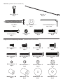
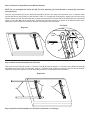
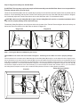
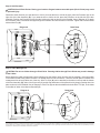
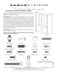
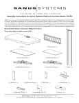
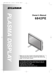
Assembly Instructions for Model: VMAA26
Thank you for choosing a Sanus Systems VisionMount™ wall mount. The VMAA26 is designed to mount up to 50” Flat panel televisions
weighing up to 130 lb. to a vertical wall. It allows you to tilt the television from +5° to -15°. It will also extend 25.75” away from the wall,
swivel up to 180°, and roll ± 6°.
CAUTION: The size and weight of your television must not exceed 50” [1270 mm] diagonally and 130 Lbs [59 Kg]. The wall
must be capable of supporting five times the weight of the television plus the wall mount. Never use defective parts. Improper
installation may cause property damage or personal injury. Do not use this product for any purpose that is not explicitly
specified by Sanus Systems.
If you do not understand these directions, or have any doubts about the safety of the installation, please call a qualified contractor
or contact Sanus at 800.359.5520 or www.sanus.com. Our customer service representatives can quickly assist you with installation
questions and missing or damaged parts. Replacement parts for products purchased through authorized dealers will be shipped directly
to you. Check carefully to make sure that there are no missing or defective parts. Sanus Systems can not be liable for damage or injury
caused by incorrect mounting, incorrect assembly, or incorrect use. Please call Sanus Systems before returning products to the point of
purchase.
NOTE: This mount is not intended for use on brick, concrete block, concrete, or steel wall studs. Typical wall anchors do not
have sufficient holding power to support this mount. It is up to the installer to verify the safety of any installation method or
hardware that is not provided by or recommended by Sanus Systems. Sanus Systems makes every effort to assure all necessary
television mounting hardware is included. If the television mounting hardware you need is not included please consult your
local hardware store or call Sanus Systems
Required Tools: 3/16” drill bit, drill, adjustable or crescent wrench, Phillips screwdriver.
Supplied Parts: (Some parts are not shown at same scale)
Wall Plate - A
Qty. 1
I” Diameter Tube - D
Qty. 2
Arm Assembly - B
Qty. 1
Monitor Bracket - E
Qty. 2
Preventor - C
Qty. 1
Vise Assembly - F
Qty. 4
Sanus Systems 2221 Hwy 36 West, Saint Paul, MN 55113 09.26.06 (6901-100017)
Customer Service: 800.359.5520. See complementary Sanus products at www.sanus.com
Hardware: (Hardware shown is actual size)
Wire Tie - H
Qty. 10
Wire Tie Clip - G
Qty. 7
Lag Bolt - I
Qty. 4
2” Carriage Bolt - L
Qty. 4
Lag Bolt Washer - J
Qty. 4
1/4-20 Nut - M
Qty. 4
Safety Bolt - N
Qty. 3
7/32 & 3/16 Allen Keys - K
Qty. 1 Each
Preventor Bolt - O
Qty. 2
Supplied Television Mounting Hardware: (Hardware shown is actual size)
M4 x 12 mm Bolt - P
Qty. 4
M5 x 12 mm Bolt - Q
Qty. 4
M6 x 12 mm Bolt - R
Qty. 4
M8 x 16 mm Bolt - S
Qty. 4
M4 x 30 mm Bolt - T
Qty. 4
M5 x 30 mm Bolt - U
Qty. 4
M6 x 35 mm Bolt - V
Qty. 4
LM8 x 30 mm Bolt - W
Qty. 4
M4 Lock Washer - X
Qty. 4
M5 Lock Washer - Y
Qty. 4
M6 Lock Washer - Z
Qty. 4
M8 Lock Washer - AA
Qty. 4
M4/M5 Spacer - BB
Qty. 4
M/M8 Spacer - CC
Qty. 4
M4/M5 Washer - DD
Qty. 8
M6/M8 Washer - EE
Qty. 4
Step 1: Mounting Monitor Brackets to a Televisions with a flat back
NOTE: For TVs with a curved back or any other obstruction See Step 2. After completing this step, proceed to Step 3.
Determine the diameter of the Bolt (P,Q,R,S) your TV requires by hand threading them into the threaded insert on the back of the
TV. If you encounter any resistance stop immediately. Once you have determined the correct diameter, refer to the appropriate
Diagram below. Thread the Bolt through the appropriate Lock Washer (X,Y,Z,AA), a Washer (DD,EE), the Monitor Bracket (E) and
finally into the TV. Make sure the Monitor Brackets are vertically centered and level with each other. Repeat this process until each
Monitor Bracket is secured to the TV with two bolts.
M4 Diameter Bolt
M6 Diameter Bolt
E
E
P
Z
X
R
EE
DD
Diagram 1
M8 Diameter Bolt
M5 Diameter Bolt
E
E
S
Q
DD
Y
EE
AA
Step 2: Mounting the Monitor Brackets to Televisions with a curved back or other obstruction.
Determine the diameter of the Bolt (T,U,V,W) your TV requires, by hand threading them into the threaded insert on the back of the
TV. If you encounter any resistance stop immediately. Once you have determined the correct diameter, refer to the appropriate
Diagram below. Thread the Bolt through the appropriate Lock Washer (X,Y,Z,AA), a Washer (DD,EE), the Monitor Bracket (E),
a second Washer (DD - M4/M5 diameter only), a Spacer (BB,CC), and finally into the TV. Make sure the Monitor Brackets are
vertically centered and level with each other. Repeat the process until each Monitor Bracket is secured to the TV with two bolts.
M4 Diameter Bolt
M6 Diameter Bolt
T
DD
V
X
DD
BB
Z
EE
E
E
CC
Diagram 2
M8 Diameter Bolt
M5 Diameter Bolt
DD
W
U
AA
Y
EE
DD
E
E
BB
CC
Step 3: Add the Vise Assemblies to the Monitor Brackets:
NOTE: Do not overtighten the 1/4-20 Nut (M). The Vise Assembly (F) should be able to rotate freely around the
Carriage Bolt (L).
Place the Vise Assembly (F) into the Monitor Bracket (E) so that the two Jaws point toward the set of 1” diameter holes
and the Allen Bolt is facing away from the television. Place a 2” Carriage Bolt (L) through the square hole in the side of the
Monitor Bracket, and the Vise Assembly; then, through the square hole in the other side of the Monitor Bracket. Thread and
tighten a 1/4-20 Nut (M) onto the end of the 2” Carriage bolt. Repeat this step for the bottom of the Monitor Bracket; then,
repeat this process for the second Monitor Bracket. See Diagram 3 and Vise Detail.
Vise Detail
Diagram 3
Jaws
1” Dia.
Hole
F
Allen
Bolt
L M
E
Step 4: Attach the Arm Assembly to the Television
Align each Vise Assembly (F) so that a 1” Diameter Tube (D) will pass through the 1” round hole in the Monitor Bracket (E)
and between the jaws of the Vise Assembly. Insert a 1” Diameter Tube through the top hole in the first Monitor Bracket.
Repeat this step for the Bottom hole in the same Monitor Bracket. See Diagram 4a for assistance.
Diagram 4a
D
F
E
F
Step 4: Attach the Arm Assembly to the Television (Continued on next page.)
E
Step 4: Attach the Arm Assembly to the Television (Continued)
CAUTION: The 1” Diameter Tubes (D) must extend beyond the outside edges of both Monitor Brackets (E) and
the Allen Bolts in all 6 Vise Assemblies (F) must be tightened. Failure to do this will result in an installation that
unstable and may result in property damage and/or personal injury.
Position the Arm Assembly (B) so the hook shaped tab shown in Detail View of Diagram 4b is on the top. Line up the two
1” diameter holes in the Monitor Bracket (E) at the other end of the Arm Assembly with the with the 1” Diameter Tubes
(D). Push the 1” Diameter Tubes through the bracket on the Arm Assembly; then, through the other Monitor Bracket.
Make sure the Vise Assemblies (F) on both the Arm Assembly and the second Monitor Bracket are aligned so that the
1” Diameter Tubes will pass between the jaws.
NOTE: Do not over-tighten the Vise Assembly (F), or the Vise Assemblies in the Arm Assembly (B). When tightening
the Vise Assemblies, turn the Allen Bolt in until resistance is felt; then, tighten the Allen Bolt approximately 1 & 1/2
turns or until the head of the Allen Bolt is slightly above the surface of the Vise Assembly. The 1” Diameter Tubes
(D) must not be able to move from side-to-side when the Vise Assembly is properly tightened.
Once the 1” Diameter Tubes are in place, tighten the allen bolts on the 4 Vise Assemblies in the two Monitor Brackets with
the 3/16 Allen Key (K) to lock the television to the mount. Slide the Arm Assembly into the desired position between the
two Monitor Brackets (Sanus recommends Arm Assembly be centered between the Monitor Brackets) and tighten the two
remaining Allen Bolts in the Vise Assemblies inside the Arm Assembly.
Detail View
F
Diagram 4b
Tab
D
E
D
B
E
F
Step 5: Attach the Wall Plate: Wood Stud installation only.
CAUTION: Do not overtighten the Lag Bolts. Tighten Lag Bolts (I) only until the Lag Bolt Washer (J) is pulled
firmly against the Wall Plate (A). If there is a layer of drywall or other material, this drywall or other material may not
exceed 5/8 inch [15.8 mm] in thickness. Failure to heed this caution may result in property damage and/or personal
injury.
The Wall Plate (A) must be mounted to two wood studs at
least 12” apart. Use a high quality stud sensor to locate two
adjacent studs. Verify where the studs are located with an A
awl or thin nail. Pre-drill a 2.5” deep hole in each stud at
the desired height using a 3/16” drill bit. Make sure these
holes are in the center area of the studs and level with I
each other. Use the Wall Plate as a template to mark the
location of the second hole in each stud. Drill 2.5” deep
holes using the 3/16” drill bit in the marked location. Attach
the Wall Plate to the wall using four Lag Bolts (I) and four
Lag Bolt Washers (J). Make sure the Wall Plate is oriented
so the flat surface in the center of the plate is against the
wall. See Diagram 5 for assistance.
Diagram 5
Stud
J
Drywall cut away
to show studs.
Step 6: Hang the assembly onto the Wall Plate
CAUTION: This step may require two people to lift the assembly onto the Wall Plate. Sanus is not responsible for
property damage and/or personal injury.
Orient the Arm Assembly (B) so the arm extends directly away from the television and the Transfer Plate is parallel with the
television. Lift the assembly and hook the Transfer Plate onto the tab on the top of the Wall Plate (A) as shown in Diagram
6a. Horizontally adjust the Transfer Plate side to side on the Wall Plate until it is in the desired location.
CAUTION: make sure the Saftey Bolt (N) is tight. A loose Safety Bolt will result in an unstable installation which
may result in property damage and/or personal injury.
Thread each Safety Bolt (N) into one of the three holes in the bottom of the Transfer Plate and tighten them so that they are
behind the Tab on the bottom of the Wall Plate as shown in Diagram 6b.
Diagram 6a
Diagram 6b
B
A
Tab
N
Transfer Plate
Step 7: Leveling the Monitor and Adjusting the Tension
CAUTION: Do not remove the Tension Nuts in Diagram 7. Removing Tension Nuts will result in property damage.
Once the television is mounted onto the Wall Plate (A), and the Safety Bolts (N) are tight, it can be adjusted to level. Slightly loosen
the two Allen Bolts on the back of the Arm Assembly (B). Once the Allen Bolts are loosened, the television can be adjusted ±6º until
level. When the television is level retighten the two Allen Bolts. The tilt can be adjusted by setting the tension of the Tension Knobs
and tilting the television. The Tension Nuts labeled in Diagram 7 can be slightly loosened or tightened using the 7/32 Allen Key (K)
and wrench to adjust the tension of the Arm Assembly. If you need to adjust the Tension Nut closest to the TV, you must remove
the Safety Bracket, adjust the tension and re-install the Safety Bracket as shown in Safety Bracket Installation.
Safety Bracket Installation
Diagram 7
Tension
Nut
B
A
Tension
Knob
Allen
Bolt
Tension
Nut
N
Safety
Bracket
Step 8: Add Preventor
CAUTION: Avoid Pinch Points. Placing your hands or fingers between moveable parts (Pinch Points) may result
in personal injury
Determine which direction you want the Arm to fold. If you want the Arm to fold to the right, place the Preventor (C) on the
right side of the Arm Assembly (B). If you want the Arm to fold to the left, place the Preventor on the left side of the Arm
Assembly. Position the Preventor so the flat side is facing the Idler as shown in the Detailed View of Diagram 8. To attach
the Preventor, place a Preventor Bolt (O) through the Preventor and into the holes in the Idler. Tighten the Preventor Bolts
with an Allen Key (K).
Diagram 8 Detail View
C
O
Idler
Step 9: Cable Management
CAUTION: Do not run Cables through a Pinch Point. Running Cables through Pinch Points may result in damage
to the Cables.
Before beginning cable management pull the television into the position as far from the wall as possible. Leave some slack
in the cables so that during motion so there is no added tension on the connectors. There are several places to attach Wire
management ties to keep cables out of the way. Wire Tie Clips (G) can be attached to the holes in the top and the bottom
of the Arm Assembly (B), sides of the Preventor (C) and the top and bottom of the pillow block by simply pressing them into
place as shown in the Detailed View of Diagram 9. Wire Ties (H) can then be added to both the Wire Tie Clips, or the holes
in the sides of either of the Monitor Brackets (E).
Diagram 9
Detail view
G
B
C
G
CSAV, Inc. and its affiliated corporations and subsidiaries (collectively, “CSAV”), intend to make this manual accurate and complete. However, CSAV makes no claim that the information contained herein
covers all details, conditions, or variations. Nor does it provide for every possible contingency in connection with the installation or use of this product. The information contained in this document is subject to
change without notice or obligation of any kind. CSAV makes no representation of warranty, expressed or implied, regarding the information contained herein. CSAV assumes no responsibility for accuracy,
completeness or sufficiency of the information contained in this document.