1
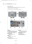
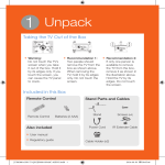
01-BN68-00633F-02Eng.qxd
5/23/04 1:13 PM
Page 5
Viewing the Connection Panel
< LW17M24C >
< LW15M23C / LW20M21C / LW20M22C >
Power Input
Power Input
Option
SCART
Whenever you connect an audio or video system to your set,
ensure that all elements are switched off.
Refer to the documentation supplied with your equipment for
detailed connection instructions and associated safety precautions.
English-1
01-BN68-00633C-00Eng.qxd
4/18/04 7:35 AM
Page 6
Viewing the Connection Panel
Connecting an Aerial or Cable Television Network (depending on the model)
To view television channels correctly, a signal must be received by the set from one of the
following sources:
- An outdoor aerial
- A cable television network
- A satellite network
Connecting a Set-Top Box, VCR or DVD
- Connect the VCR, or DVD SCART cable to the SCART connector of the VCR, or DVD.
- If you wish to connect both the Set-Top Box and VCR (or DVD), you should connect the
Set-Top Box to the VCR (or DVD) and connect the VCR (or DVD) to your set.
Connecting a Computer
- Connect the 15 Pin D-SUB connector to the PC video connector.
- Connect the stereo audio cable to the “Audio (ST)” jack on the rear of your set and the other end to
the “Audio Out” jack of the sound card on your computer.
➣ 15 Pin D-SUB connector
English-2
Pin
Separate H/V
Composite H/V
1
2
3
4
5
6
7
8
9
10
11
12
13
14
15
Red (R)
Green (G)
Blue (B)
Grounding
Grounding (DDC return)
Grounding - Red (R)
Grounding - Green (G)
Grounding - Blue (B)
No connection
Grounding - Sync. / Self test
Grounding
DDC - SDA (Data)
Horizontal Sync.
Vertical Sync.
DDC - SCL (Clock)
Red (R)
Green (G)
Blue (B)
Grounding
Grounding (DDC return)
Grounding - Red (R)
Grounding - Green (G)
Grounding - Blue (B)
No connection
Grounding - Sync. / Self test
Grounding
DDC - SDA (Data)
Horizontal/Vertical Sync.
Not used
DDC - SCL (Clock)
01-BN68-00633F-02Eng.qxd
5/14/04 9:02 AM
Page 7
Viewing the Connection Panel
Connecting External A/V Devices
- Connect RCA or S-VIDEO cables to an appropriate external A/V device such as a VCR, DVD
or Camcorder.
- Connect RCA audio cables to “(MONO)L-AUDIO-R” on the rear of your set and the other ends to
corresponding audio out connectors on the A/V device.
Connecting Headphones
- Plug a set of headphones into the 3.5mm mini-jack socket on the right-side of the set.
- Headphones may be connected to the headphone output on the right-side of the set.
While the headphones are connected, the sound from the built-in speakers will be disabled.
Kensington Slot
- This television has been designed to apply a burglarproof lock.(See next page.)
Retractable Stand
Note: The maximum tilt angle is 13 degrees in the backward direction.
Please do not tilt the TV outside the specified range. Using excessive force
to tilt the TV may cause permanent damage to the mechanical part of the stand.
< LW20M21C / LW20M22C > model swivels left and right.
< LW15M23C / LW17M24C >
< LW20M21C / LW20M22C >
English-3
04-BN68-00633F-02Eng.qxd
5/13/04 5:17 PM
Page 51
Using the Anti-Theft Kensington Lock
The Kensington lock is a device used to
physically fix the system when using it in
a public place. The locking device has to
be purchased separately.
The appearance and locking method may
differ from the illustration depending on
the manufacturer. Please refer to the
manual provided with the Kensington
lock for proper use.
Cable
Figure 2
Figure 1
<Optional>
1.
Insert the locking device into the Kensington slot on the LCD TV (Figure 1),
and turn it in the locking direction (Figure 2).
2.
Connect the Kensington lock cable.
3.
Fix the Kensington lock to a desk or a heavy stationary object.
Installing VESA compliant mounting devices
SC
T
AR
SC
T
AR
T
AR
SC
Mounting pad
< LW15M23C / LW17M24C >
< LW20M21C / LW20M22C >
Align the mounting interface pad with the holes in the rear cover mounting pad and secure it with the four
screws that come with the arm-type base, wall mount hanger or other bases.
English-4
04-BN68-00633F-02Eng.qxd
5/13/04 5:17 PM
Page 52
Installing the Wall Mount Kit
Note : This installation is to be used when attaching the wall mount to a concrete wall.
When attaching to other building materials, please contact your nearest dealer.
Components
Please use provided components or parts to install the Wall Mount Kit.
Bracket
Anchors : 3EA
Screws : 3EA
How to assemble the Wall Mount Kit
Mark the location of hole on the wall using installation guide.
1
Make over 35mm- depth- hole on the marked location using
5.0-diameter drill.
Fix anchors on each hole on the wall.
Connect bracket to the wall with screws after fitting anchors
into the bracket holes.
Note : If the bracket is not firmly fixed to the wall, LCD TV can fall off.
2
After placing LCD TV on cushion or other soft material, turn over
LCD TV in the direction of arrow while grabbing bottom of the
stand.
English-5
Installation Guide
04-BN68-00633F-02Eng.qxd
5/14/04 12:58 PM
Page 53
Installing the Wall Mount Kit
3
Adjust LCD TV to the hook on the bracket and move in the direction of the arrow(Left) so that LCD TV can be
completely fixed to the bracket.
When bracket is assembled on the wall
How to hang LCD TV up on a hook
When installation is completed
4
Remove Installation Guide after completing setup of monitor on the wall.
5
Push the LCD TV up and shift to the right to detach it from bracket.
When moving or transferring to other areas, reverse No. 3 procedure so as to disconnect LCD TV with ease.
How to assemble the Wall Mount Kit
(1) Angle adjustment section of
(2) Angle abjustment section
general stand-besd LCD TV
while converting the form
(1->3, 3->1)
(3) Angle adjustment section of
wall-mounted LCD TV
Picture(1) shows the adjustment angle(0°~ 13°)when you use LCD TV in its general form(stand-based LCD TV).
Excessive tilting can turn LCD TV over which might cause damage to LCD TV.
Picture(2) shows the adjustment angle(13°~ 80°)when you convert stand-based LCD TV into wall-mounted one.
Picture(3) shows the adjustment angle(0°~ 10°)when you use wall-mounted LCD TV after fixing it to wall.
Note : Picture (2) shows the angle adjustment section while LCD TV is being converted from stand-based one to
wall-mounted one or vice versa.
- Click" sound indicates section change from 1 to 2 or 3 to 2(1->2, 3->2).
English-6
04-BN68-00633F-02Eng.qxd
5/14/04 12:58 PM
Page 54
Installing the Wall Mount Kit
Note : This installation is to be used when attaching the wall mount to a concrete wall.
When attaching to other building materials, please contact your nearest dealer.
Components
Please use provided components or parts to install the Wall Mount Kit.
Bracket
Anchors : 4EA
Screws : 4EA
How to assemble the Wall Mount Kit
1
Mark the location of hole on the wall using installation guide.
Make over 35mm- depth- hole on the marked location using
5.0-diameter drill.
Fix anchors on each hole on the wall.
Connect bracket to the wall with screws after fitting anchors
into the bracket holes.
Note : If the bracket is not firmly fixed to the wall, LCD TV can fall off.
2
You may use LCD TV right after fixing it to the wall since stand is
wrapped already turned over as shown in the picture
3
When using LCD TV in stand-based form, place the product
on a cushion or other soft materials. Then turn over
stand following the arrow direction below only after pressing button on
the connected part where LCD TV is attached to stand.
(Turn over stand in the opposite direction after pressing button when
using LCD TV in wall-mounted form as well.)
English-7
Installation Guide
04-BN68-00633F-02Eng.qxd
5/14/04 12:58 PM
Page 55
Installing the Wall Mount Kit
4
Adjust LCD TV to the hook on the bracket and move in the direction of the arrow(Left) so that LCD TV can be
completely fixed to the bracket.
When bracket is assembled on the wall
How to hang monitor up on a hook
When installation is completed
5
Remove Installation Guide after completing setup of LCD TV on the wall.
6
Push the LCD TV up and shift to the right to detach it from bracket.
When moving or transferring to other areas, reverse No. 4 procedure so as to disconnect LCD TV with ease.
How to adjust an angle
(1) Angle adjustment section of
(2) Angle abjustment section
general stand-besd LCD TV
while converting the form
(1->3, 3->1)
(3) Angle adjustment section of
wall-mounted LCD TV
Picture(1) shows the adjustment angle(0°~ 13°)when you use LCD TV in its general form(stand-based LCD TV).
Excessive tilting can turn LCD TV over which might cause damage to LCD TV.
Picture(2) shows the adjustment angle(13°~ 80°)when you convert stand-based LCD TV into wall-mounted one.
Picture(3) shows the adjustment angle(0°~ 10°)when you use wall-mounted LCD TV after fixing it to wall.
Note : Picture (2) shows the angle adjustment section while LCD TV is being converted from stand-based one to wallmounted one or vice versa.
English-8