1
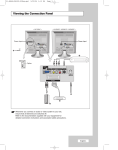
01 BN68-00816A-00.qxd
2/1/05 4:14 PM
Page 3
Y O U R N E W TV
Rear Panel Jacks
Use the rear panel jacks to connect an A/V component that will be connected
continuously, such as a VCR or a DVD player.
For more information on connecting equipment, see pages 6~12.
<LN15S51B>
<LN20S51B>
PC IN
AV IN
Connect to the video output port on your PC.
Video and audio inputs for external
devices, such as a camcorder or VCR.
COMPONENT IN (480i/480p)
Connect a component video/audio.
KENSINGTON LOCK
(See page 56)
S-VIDEO IN
Connect an S-Video signal from a
camcorder or VCR.
ANT IN
Connect to an antenna or to a cable
TV system.
PC AUDIO IN
Connect to the audio output jack on your PC.
English-1
POWER INPUT
Connect the supplied power cord.
01 BN68-00816A-00.qxd
2/1/05 4:14 PM
Page 6
C h a p t e r Tw o
I N S TA L L AT I O N
Connecting VHF and UHF Antennas
If your antenna has a set of leads that
look like this, see “Antennas with
300-ohm Flat Twin Leads” below.
If your antenna has one lead that looks
like this, see “Antennas with 75-ohm
Round Leads” on page 7.
If you have two antennas, see “Separate
VHF and UHF Antennas” on page 7.
Antennas with 300-ohm Flat Twin Leads
If you are using an off-air antenna (such as a roof antenna or “rabbit ears”) that has
300-ohm twin flat leads, follow the directions below.
1
Place the wires from the
twin leads under the
screws on a 300-75 ohm
adaptor (not supplied).
Use a screwdriver to
tighten the screws.
2
Plug the adaptor into
the ANT IN terminal on
the back of the TV.
English-2
01 BN68-00816A-00.qxd
2/1/05 4:14 PM
Page 7
I N S TA L L AT I O N
Antennas with 75-ohm Round Leads
1
Plug the antenna lead
into the ANT IN terminal
on the back of the TV.
Separate VHF and UHF Antennas
If you have two separate antennas for your TV (one VHF and one UHF), you must combine
the two antenna signals before connecting the antennas to the TV.
This procedure requires an optional combiner-adaptor (available at most electronics shops).
1
Connect both antenna
leads to the combiner.
VHF
UHF
2
Plug the combiner into
the ANT IN terminal on
the back of the TV.
ANT IN
VHF
UHF
Connecting Cable TV
To connect to a cable TV system, follow the instructions below.
Cable without a Cable Box
Because this TV is cable-ready,
you do not need a cable box to
view unscrambled cable channels.
1
Plug the incoming
cable into the ANT IN
terminal on the back
of the TV.
English-3
01 BN68-00816A-00.qxd
2/1/05 4:14 PM
Page 8
I N S TA L L AT I O N
Connecting to a Cable Box that Descrambles All Channels
This terminal might be labeled
“ANT OUT”, “VHF OUT”, or
simply, “OUT”.
1
Find the cable that is
connected to the
ANT OUT terminal on
your cable box.
ANT IN
ANT OUT
2
Connect the other end
of this cable to the
ANT IN terminal on the
back of the TV.
Connecting to a Cable Box that Descrambles Some Channels
If your cable box descrambles only some channels (such as premium channels), follow the
instructions below. You will need a two-way splitter, an RF (A/B) switch, and four lengths
of RF cable. (These items are available at most electronics stores.)
This terminal might be labeled
“ANT IN”, “VHF IN”, or simply,
“IN”.
1
Find and disconnect
the cable that is
connected to the
ANT IN terminal on
your cable box.
ANT IN
2
Connect this cable to a
two-way splitter.
Incoming
cable
Splitter
3
Connect a RF cable
between an OUTPUT
terminal on the splitter
and the IN terminal on
the cable box.
Incoming
cable
Splitter
Cable Box
English-4
01 BN68-00816A-00.qxd
2/1/05 4:14 PM
Page 9
I N S TA L L AT I O N
4
Connect an RF cable
between the ANT OUT
terminal on the cable
box and the B–IN
terminal on the A/B
switch.
Incoming
cable
Splitter
RF (A/B)
Switch
Cable Box
5
Connect another cable
between the other
OUT terminal on the
splitter and the A–IN
terminal on the RF
(A/B) switch.
Incoming
cable
Splitter
RF (A/B)
Switch
Cable Box
6
Connect the last
RF cable between the
OUT terminal on the
RF (A/B) switch and
the ANT IN terminal on
the rear of the TV.
ANT IN
Incoming
cable
TV Rear
Splitter
Cable Box
RF (A/B)
Switch
After you’ve made this connection, set the A/B switch to the “A” position for normal
viewing. Set the A/B switch to the “B” position to view scrambled channels.
(When you set the A/B switch to “B”, you will need to tune your TV to the cable box’s
output channel, which is usually channel 3 or 4.)
English-5
01 BN68-00816A-00.qxd
2/1/05 4:14 PM
Page 10
I N S TA L L AT I O N
Connecting a VCR
These instructions assume that you have already connected your TV to an antenna or a
cable TV system (according to the instructions on pages 6-9).
Skip step 1 if you have not yet connected to an antenna or a cable system.
1
Unplug the cable or
antenna from the
back of the TV.
2
Connect the cable or
antenna to the ANT IN
terminal on the back of
the VCR.
VCR Rear Panel
Incoming Cable
or Antenna
3
Connect an RF cable
between the ANT OUT
terminal on the VCR
and the ANT IN
terminal on the TV.
TV Rear Panel
VCR Rear Panel
RF Cable <Optional>
An RF cable is usually included with a VCR. (If not, check your local electronics store).
4
Connect an audio cable
between the AUDIO OUT
jacks on the VCR and
the AV IN [L-AUDIO-R]
jacks on the TV.
TV Rear Panel
VCR Rear Panel
Audio Cable <Optional>
If you have a “mono” (non-stereo) VCR, use the Y-connector (not supplied) to hook up to the left
and right audio input jacks of the TV.
English-6
01 BN68-00816A-00.qxd
2/1/05 4:14 PM
Page 11
I N S TA L L AT I O N
5
Connect a video cable
between the
VIDEO OUT jack on the
VCR and the AV IN
[VIDEO] jack on the TV.
TV Rear Panel
VCR Rear Panel
Video Cable <Optional>
Follow the instructions in “Viewing a VCR or Camcorder Tape” to view your VCR tape.
* Each external input source device has a different back panel configuration.
Connecting an S-VHS VCR
Your Samsung TV can be connected to an S-Video signal from an S-VHS VCR.
(This connection delivers a better picture as compared to a standard VHS VCR.)
1
To begin, follow steps
1–3 in the previous
section to connect the
antenna or cable to
your VCR and your TV.
TV Rear Panel
VCR Rear Panel
RF Cable <Optional>
An RF cable is usually included with a VCR. (If not, check your local electronics store).
2
Connect an audio cable
between the AUDIO
OUT jacks on the VCR
and the AV IN
[L-AUDIO-R] jacks on
the TV.
TV Rear Panel
VCR Rear Panel
Audio Cable <Optional>
English-7
01 BN68-00816A-00.qxd
2/1/05 4:14 PM
Page 12
I N S TA L L AT I O N
3
Connect an S-Video
cable between the
S-VIDEO OUT jack on
the VCR and the
S-VIDEO IN jack on the
TV.
TV Rear Panel
VCR Rear Panel
S-Video Cable <Optional>
An S-video cable is usually included with an S-VHS VCR.
(If not, check your local electronics store.)
* Each external input source device has a different back panel configuration.
Connecting a DVD Player
The rear panel jacks on your TV make it easy to connect a DVD player to your TV.
1
Connect an audio cable
between the
COMPONENT IN
[L-AUDIO-R] jacks on
the TV and the AUDIO
OUT jacks on the DVD
player.
TV Rear Panel
DVD Player Rear Panel
Audio Cable <Optional>
2
Connect a component
cable between the
COMPONENT IN
[Y, PB, PR] jacks on the
TV and the
COMPONENT
[Y, PB, PR] jacks on
the DVD player.
TV Rear Panel
DVD Player Rear Panel
Component Cable <Optional>
Note : For an explanation of Component video, see your DVD player owner's manual.
The component terminal of this set only supports 480i/480p resolution.
* Each external input source device has a different back panel configuration.
English-8
04 BN68-00816A-00.qxd
2/1/05 4:21 PM
Page 57
APPENDIX
Retractable Stand
Note: The maximum tilt angle is 13 degrees in the backward direction.
Please do not tilt the TV outside the specified range. Using excessive force
to tilt the TV may cause permanent damage to the mechanical part of the stand.
English-9
04 BN68-00816A-00.qxd
2/1/05 4:21 PM
Page 58
APPENDIX
Installing VESA compliant mounting devices
Mounting pad
<1>
<2>
<1> Fold the stand pressing the button on the back of the stand.
<2> Align the mounting interface pad with the holes in the stand bottom and secure it with the four
screws that come with the arm-type base, wall mount hanger or other bases.
Wall Mount Instructions
The following instructions apply to a hollow sheet-rock wall only. Tools/Hardware needed - Philips
screwdriver, four toggle bolts, 5/8in dia. Drill bit and drill. Contact Ergotron at (800) 888-8458 to
purchase the triple pivot direct mount adapter and wall mount bracket kit.
• LN-R1550 (15") : No.
No.
• LN-R2050 (20") : No.
No.
47
97
47
97
-
007
101
007
101
-
099
003
099
003
(Pivot direct mount adapter)
(Wall mount bracket kit)
(Pivot direct mount adapter)
(Wall mount bracket kit)
Align the wall mount bracket on the wall at the desired height, making sure that the bracket will be
mounted between the wall studs. Mark the four corner openings and drill four 5/8-diameter holes.
Assemble the wall mount kit according to the instructions provided with it. Securely attach Ergotron’s
flat panel, triple pivot direct mount adapter to the back of the TV using the four 4mm,
0.7 pitch x 10mm screws provided with the arm. Secure the assembly to the wall using four 3/16 by
3-inch long toggle bolts.
English-10
04 BN68-00816A-00.qxd
2/1/05 4:21 PM
Page 59
APPENDIX
Installing the Wall Mount Kit
Note : This installation is to be used when attaching the wall mount to a concrete wall.
When attaching to other building materials, please contact your nearest dealer.
Components
Please use provided components or parts to install the Wall Mount Kit.
Bracket
Anchors : 3EA
Screws : 3EA
How to assemble the Wall Mount Kit
1
Mark the location of hole on the wall using installation guide.
Make over 35mm- depth- hole on the marked location using
5.0-diameter drill.
Fix anchors on each hole on the wall.
Connect bracket to the wall with screws after fitting anchors
into the bracket holes.
Note : If the bracket is not firmly fixed to the wall, LCD TV can fall off.
2
You may use LCD TV right after fixing it to the wall since stand is
wrapped already turned over as shown in the picture below.
3
When using LCD TV in stand-based form, place the product on a
cushion or other soft materials. Then turn over stand following the
arrow direction below only after pressing button on the connected
part where LCD TV is attached to stand.
(Turn over stand in the opposite direction after pressing button when
using LCD TV in wall-mounted form as well.)
English-11
Installation Guide
04 BN68-00816A-00.qxd
2/1/05 4:21 PM
Page 60
APPENDIX
Installing the Wall Mount Kit
4
Adjust LCD TV to the hook on the bracket and move in the direction of the arrow(Left) so that LCD TV can be completely fixed to the bracket.
When bracket is assembled on the wall
How to hang monitor up on a hook
When installation is completed
5
Remove Installation Guide after completing setup of LCD TV on the wall.
6
Push the LCD TV up and shift to the right to detach it from bracket.
When moving or transferring to other areas, reverse No. 4 procedure so as to disconnect LCD TV with ease.
How to adjust an angle
(1) Angle adjustment section of
general stand-besd LCD TV
(2) Angle abjustment section
while converting the form
(1->3, 3->1)
(3) Angle adjustment section of
wall-mounted LCD TV
Picture (1) shows the adjustment angle (0°~ 13°) when you use LCD TV in its general form (stand-based
LCD TV).
Excessive tilting can turn LCD TV over which might cause damage to LCD TV.
Picture (2) shows the adjustment angle (13°~ 80°) when you convert stand-based LCD TV into wall-mounted
one.
Picture (3) shows the adjustment angle (0°~ 10°) when you use wall-mounted LCD TV after fixing it to wall.
Note : Picture (2) shows the angle adjustment section while LCD TV is being converted from stand-based
one to wall-mounted one or vice versa.
- Click" sound indicates section change from 1 to 2 or 3 to 2 (1->2, 3->2).
English-12