1
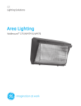
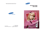
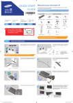
QUICK START
GUIDE
Welcome to your new Smart TV!
The following instructions cover assembling, connecting, and setting up your new TV. Make sure
you have the accessories listed below.
1
2
1-1
1-2
Included in this box
Object
wall
TV
BN68-05629A-00
1-2
1-1
wall
TV
One Connect Accessories:
One connect, one connect cable
R
L
Object
31mm
1-1.If the wall is not flat, a gap may form
after the installation is completed and
this may result in a poor finish.
1-2.The TV cannot be mounted on the wall
if there is an object between the TV and
the wall that is 31 mm or thicker.
Check the wall’s type, thickness, and flatness.
Smart Touch Control &
Batteries (AAA x 2)
3
Check the L and R markings on the front sides of the wall mount brackets.
4
Also included: User manual, regulatory guide, IR extender,
component adapter, RCA adapter x 2, power cord, Ferrite core
F
3D Glasses Accessories:
3D Active glasses, USB charge cable
Step 1
Installing the
Wall Mount
Connect
Audio Devices
Connect
devices
Step
Step
Step
1
2
3
Using the
Smart Touch
Control
Power on and
start the initial
setup
Step
Step
4
5
B
Drive the level adjustment screw into the hole to get it prepared for use.
5
Attach the length adjustment bars to the two wall mount brackets using screws.
6
Installing the Wall Mount
Installation Precautions
E
]] Check the type of the wall before installing.
•• Use the provided accessories and parts to install the wall mount.
•• Install the product onto a flat wall surface only.
Installation requirements for each wall type
•• Avoid the following areas to ensure the best product performance and prevent malfunctions:
•• Can only be mounted on a concrete or interior wall of sufficient thickness. Refer to the diagrams
below.
-- Areas that are susceptible to vibration and impact: The TV might come loose from the mount
and be damaged.
D
Min. 50 mm
-- Next to fire sprinklers: Heat generated by the TV could activate the sprinkler.
With MDF
or plywood
reinforcement
-- Near high-voltage cables: Electronic interference from the high-voltage cables may disrupt
the screen display.
-- Near a heating appliance: The product may overheat and malfunction.
Min.
25 mm
Min. 30 mm
Min.
50 mm
MDF or PW
(Excluding
drywall thickness)
MDF or PW
-- Check the stability of the wall surface.
Art Wall
-- If the wall is too weak, reinforce it before installing the mount.
•• Do not remove a section of the wall and install the mount there.
•• Plug all the cables into the correct ports and connectors before installing the wall mount.
Min. 10 mm
Min. 10 mm
MDF or PW
MDF or PW
MDF = Medium Density
Fiberboard
•• Once installed, the gap between the wall surface and the TV should be at least 31 mm.
PW = Plywood
•• For the types of walls the TV can be mounted on, check the model of your TV and then the
corresponding installation guide on the back of the product.
Min.
25 mm
Requirements
Min. 30 mm
•• Verify the location of the studs first and use wall screws.
Composite
Concrete Wall
(Excluding
drywall thickness)
Concrete
Art Wall
Min. 10 mm
15mm
Insert the anchors and screws where marked.
7
•• Minimum Stud Size: 51x102mm or 2x4 in (Drill 3mm holes before inserting wall screws).
•• Drill the holes along the central axis of the stud.
•• Inserting the screws without pre-drilling the holes can split the stud.
MDF or PW
•• Installation is not possible on a drywall or on a wall with no internal reinforcement.
✎✎ Use only the provided accessories and parts to install the wall mount.
Place the assembly against the wall you wish to mount it on, and then mark the anchor insertion
points on the wall.
✎✎ NOTE
•• If attempting to install the product onto a non-concrete wall, consult an installation specialist
first.
Wall Mount Accessories
]] Installation on drywall with studs.
]] The manufacturer will not be held liable for any issue arising from failure
to comply with the instructions and requirements contained in this
installation guide.
MDF, PW, or Concrete
A (4)
Mounting Piece
B (8)
M4 X 8
C (4)
M4 X 47
Art Wall
0~24 mm
Wall Mount Brackets Length Adjustment
Left: 1, Right: 1
Bars
Ø25 : 2
[UN85S9VF_QSG]BN68-05629A-00ENG.indb 2
D (24)
M5 X 65
E (24)
Anchor
F (2)
M6 X 30
No internal
reinforcement
Drywall
D
Cannot install directly on drywall.
Remove the screws that hold the wall mount brackets in place.
2013-10-29 �� 1:25:40
Step 3
9
8
Connect devices
We suggest using HDMI connections whenever possible for the best picture quality. Use the included AV adapter to connect older devices.
✎✎ Please check the shape of the plugs to avoid inserting them upside down.
✎✎ The appearance of your TV may differ from the images below, depending on the model.
Best Connection : HDMI
C
A
C
A
Wired Ethernet
HDMI Cable
We suggest using HDMI whenever
possible.
HDMI 1 is the default port for a cable or
satellite set-top box.
Connect the cable
from the antenna or
cable TV outlet.
Assemble the mounting pieces A to the back of the TV as shown in the diagram.
]] Make sure to insert the pieces into the correct holes.
HDMI Port
USB Connections
You can connect USB storage devices
to the USB ports and enjoy personal
photos, videos, and music.
Use the other ports for Blu-ray players,
game consoles, and other devices.
Work with at least one person to lift the TV and mount it on to the bracket as shown in the
diagram.
10
11
wall
wall
wall
Take hold of the bottom of the TV and slightly pull it up to leave
space between the TV and the wall, and then flip the safety
hooks at both ends to secure the mounting pieces.
✎✎ If the TV is not horizontally level, adjust the level by turning
the screws as shown in the diagram.
Match the colors on your device's cables to the colors on the device's out ports.
Connect the device's cables to the included adapters, and then connect the adapters
to the appropriate ports on the TV as shown in the table below. Make sure the colors
match. The Component connection is shown on the top. The AV connection is shown
on the bottom.
Connect the IR extender to the
IR Out port to control external
devices connected to the TV
using the Smart Touch Control.
For more detailed information,
refer to the "Universal Remote
Control Setup" section in the
User manual.
Lift the bottom of the TV and then secure it in place as shown in the diagram. Connect the
cables.
Product Specifications
✎✎ Tilt angle may vary depending on the model.
Audio (L/R)
COMPONENT IN
Video
Audio (L/R)
Video
28.0
812.8
Step 4
6
Width (mm)
1267.2
Height (mm)
952
Depth (mm)
28
Weight (kg)
6.3
Wall Mount VESA Specifications (mm)
1000 x 800
Using the Smart Touch Control
Step 5
Information required:
Insert the tip of a credit card or similar item into the notch on the side of the Smart Touch Control,
and then twist the card to open and remove the remote's back cover.
•• Wi-Fi network password (if you use one)
✎✎ The UN85S9VF model requires you to connect a separate device in order to produce sound.
✎✎ To control the audio device using the TV’s remote control, use the Sound Share feature or connect the audio device to the TV’s HDMI (ARC) port.
✎✎ The TV must be connected to the Internet to use the Smart Features. If you have a wireless
network, confirm that your network router is working before you start the initial setup. If you
have a wired network, connect the TV to the network with a CAT 7 cable before you begin.
navigation
selection
scrolling
Make sure all cables are fully inserted, and that the remote has batteries installed.
I don’t know where to plug in <device>
Devices without HDMI may require the included A/V adapter.
I have extra parts
The TV includes some optional parts to help with wall mounting and cable routing.
To control the highlight, move
your thumb across the pad.
To select an item, press the
pad until you hear a click.
Move your thumb along the
ridges to quickly scroll through
items.
Pairing the Smart Touch Control
If you need to reestablish the connection between the TV and the Smart Touch Control, press the
pairing button at the back of the Smart Touch Control, pointing at the remote control sensor of
the TV.
Congratulations on your new Smart TV!
[UN85S9VF_QSG]BN68-05629A-00ENG.indb 3
Troubleshooting
The TV won’t turn on
You can connect home theater systems to the OPTICAL or
AUDIO OUT ports.
or
•• Zip code
•• Cable or satellite provider info
Plug in the TV. Press the power button on the remote to turn on the TV and start the initial set-up.
Using the touch pad
Connect Audio Devices
Power on and start the initial setup
Insert the batteries into the Smart Touch Control
✎✎ The notch’s location may vary depending on the type of Smart Touch Control provided.
Step 2
AV IN 1
AV IN 2
1267.2
203.2
Good Connection: Component (Y, PB, PR) or AV (Composite)
If you experience issues, please do not take the TV back
to the store.
In the United States of America, call us at
1-800-SAMSUNG (1-800-726-7864) or visit us at www.
samsung.com or www.samsung.com/spsn for support
and warranty service.
For other countries, refer to "Contact SAMSUNG
WORLDWIDE" in the user guide.
2013-10-29 �� 1:25:49