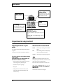
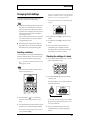
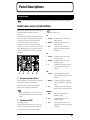
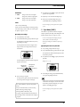
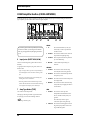
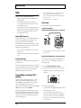
1
Owner’s Manual
Thank you, and congratulations on your choice of the Roland VGA-7 V-Guitar
Amplifier.
Before using this unit, carefully read the sections entitled:
“IMPORTANT SAFETY INSTRUCTIONS” (page 2)
“USING THE UNIT SAFELY” (page 3–4)
“IMPORTANT NOTES” (page 8–9)
These sections provide important information concerning the proper operation of the unit.
Additionally, in order to feel assured that you have gained a good grasp of every
feature provided by your new unit, this manual should be read in its entirety.
The manual should be saved and kept on hand as a convenient reference.
Conversions Used in This Manual
● Words enclosed in square brackets [ ] indicate panel buttons or knobs.
(Example)
[SYSTEM]:
SYSTEM button
[BASS]:
BASS knob
● (p. **) indicates a reference page.
Copyright © 2000 ROLAND CORPORATION
All rights reserved. No part of this publication may be reproduced in any form without the
written permission of ROLAND CORPORATION.
IMPORTANT SAFTY INSTRUCTIONS
CAUTION
RISK OF ELECTRIC SHOCK
DO NOT OPEN
ATTENTION: RISQUE DE CHOC ELECTRIQUE NE PAS OUVRIR
CAUTION: TO REDUCE THE RISK OF ELECTRIC SHOCK,
DO NOT REMOVE COVER (OR BACK).
NO USER-SERVICEABLE PARTS INSIDE.
REFER SERVICING TO QUALIFIED SERVICE PERSONNEL.
The lightning flash with arrowhead symbol, within an
equilateral triangle, is intended to alert the user to the
presence of uninsulated “dangerous voltage” within the
product’s enclosure that may be of sufficient magnitude to
constitute a risk of electric shock to persons.
The exclamation point within an equilateral triangle is
intended to alert the user to the presence of important
operating and maintenance (servicing) instructions in the
literature accompanying the product.
INSTRUCTIONS PERTAINING TO A RISK OF FIRE, ELECTRIC SHOCK, OR INJURY TO PERSONS.
IMPORTANT SAFETY INSTRUCTIONS
SAVE THESE INSTRUCTIONS
WARNING - When using electric products, basic precautions should always be followed, including the following:
1.
2.
3.
4.
5.
6.
7.
8.
9.
Read these instructions.
Keep these instructions.
Heed all warnings.
Follow all instructions.
Do not use this apparatus near water.
Clean only with a damp cloth.
Do not block any of the ventilation openings. Install in
accordance with the manufacturers instructions.
Do not install near any heat sources such as radiators,
heat registers, stoves, or other apparatus (including
amplifiers) that produce heat.
Do not defeat the safety purpose of the polarized or
grounding-type plug. A polarized plug has two blades with
one wider than the other. A grounding type plug has two
blades and a third grounding prong. The wide blade or the
third prong are provided for your safety. When the provided
plug does not fit into your outlet, consult an electrician for
replacement of the obsolete outlet.
10. Protect the power cord from being walked on or pinched
particularly at plugs, convenience receptacles, and the
point where they exit from the apparatus.
11. Only use attachments/accessories specified by the
manufacturer.
12. Never use with a cart, stand, tripod, bracket,
or table except as specified by the
manufacturer, or sold with the apparatus.
When a cart is used, use caution when
moving the cart/apparatus combination to
avoid injury from tip-over.
13. Unplug this apparatus during lightning storms or when
unused for long periods of time.
14. Refer all servicing to qualified service personnel. Servicing
is required when the apparatus has been damaged in any
way, such as power-supply cord or plug is damaged, liquid
has been spilled or objects have fallen into the apparatus,
the apparatus has been exposed to rain or moisture, does
not operate normally, or has been dropped.
For the U.K.
WARNING:
THIS APPARATUS MUST BE EARTHED
IMPORTANT: THE WIRES IN THIS MAINS LEAD ARE COLOURED IN ACCORDANCE WITH THE FOLLOWING CODE.
GREEN-AND-YELLOW: EARTH, BLUE: NEUTRAL, BROWN: LIVE
As the colours of the wires in the mains lead of this apparatus may not correspond with the coloured markings identifying
the terminals in your plug, proceed as follows:
The wire which is coloured GREEN-AND-YELLOW must be connected to the terminal in the plug which is marked by the
letter E or by the safety earth symbol or coloured GREEN or GREEN-AND-YELLOW.
The wire which is coloured BLUE must be connected to the terminal which is marked with the letter N or coloured BLACK.
The wire which is coloured BROWN must be connected to the terminal which is marked with the letter L or coloured RED.
2
USING THE UNIT SAFELY
The
symbol alerts the user to important instructions
or warnings.The specific meaning of the symbol is
determined by the design contained within the
triangle. In the case of the symbol at left, it is used for
general cautions, warnings, or alerts to danger.
Used for instructions intended to alert
the user to the risk of death or severe
injury should the unit be used
improperly.
Used for instructions intended to alert
the user to the risk of injury or material
damage should the unit be used
improperly.
* Material damage refers
other adverse effects
respect to the home
furnishings, as well
animals or pets.
The
symbol alerts the user to items that must never
be carried out (are forbidden). The specific thing that
must not be done is indicated by the design contained
within the circle. In the case of the symbol at left, it
means that the unit must never be disassembled.
to damage or
caused with
and all its
to domestic
The ● symbol alerts the user to things that must be
carried out. The specific thing that must be done is
indicated by the design contained within the circle. In
the case of the symbol at left, it means that the powercord plug must be unplugged from the outlet.
001
009
• Before using this unit, make sure to read the
instructions below, and the Owner’s Manual.
• Do not excessively twist or bend the power cord,
nor place heavy objects on it. Doing so can
damage the cord, producing severed elements and
short circuits. Damaged cords are fire and shock
hazards!
..........................................................................................................
..........................................................................................................
002a
• Do not open or perform any internal modifications on the unit.
..........................................................................................................
003
• Do not attempt to repair the unit, or replace parts
within it (except when this manual provides
specific instructions directing you to do so). Refer
all servicing to your retailer, the nearest Roland
Service Center, or an authorized Roland
distributor, as listed on the "Information" page.
..........................................................................................................
004
• Never use or store the unit in places that are:
• Subject to temperature extremes (e.g., direct
sunlight in an enclosed vehicle, near a heating
duct, on top of heat-generating equipment); or
are
• Damp (e.g., baths, washrooms, on wet floors);
or are
• Humid; or are
• Exposed to rain; or are
• Dusty; or are
• Subject to high levels of vibration.
..........................................................................................................
007
• Make sure you always have the unit placed so it is
level and sure to remain stable. Never place it on
stands that could wobble, or on inclined surfaces.
..........................................................................................................
008a
• The unit should be connected to a power supply
only of the type described in the operating instructions, or as marked on the unit.
..........................................................................................................
010
• This unit, either alone or in combination with an
amplifier and headphones or speakers, may be
capable of producing sound levels that could
cause permanent hearing loss. Do not operate for
a long period of time at a high volume level, or at
a level that is uncomfortable. If you experience
any hearing loss or ringing in the ears, you should
immediately stop using the unit, and consult an
audiologist.
..........................................................................................................
011
• Do not allow any objects (e.g., flammable material,
coins, pins); or liquids of any kind (water, soft
drinks, etc.) to penetrate the unit.
..........................................................................................................
013
• In households with small children, an adult
should provide supervision until the child is
capable of following all the rules essential for the
safe operation of the unit.
..........................................................................................................
014
• Protect the unit from strong impact.
(Do not drop it!)
..........................................................................................................
015
• Do not force the unit’s power-supply cord to share
an outlet with an unreasonable number of other
devices. Be especially careful when using
extension cords—the total power used by all
devices you have connected to the extension
cord’s outlet must never exceed the power rating
(watts/amperes) for the extension cord. Excessive
loads can cause the insulation on the cord to heat
up and eventually melt through.
..........................................................................................................
3
016
• Before using the unit in a foreign country, consult
with your retailer, the nearest Roland Service
Center, or an authorized Roland distributor, as
listed on the "Information" page.
..........................................................................................................
101a
• The unit should be located so that its location or
position does not interfere with its proper ventilation.
..........................................................................................................
102a
• Always grasp only the plug on the power-supply
cord when plugging into, or unplugging from an
outlet.
..........................................................................................................
104
• Try to prevent cords and cables from becoming
entangled. Also, all cords and cables should be
placed so they are out of the reach of children.
..........................................................................................................
105b
• If the unit could become a hazard if it moves, all
caster wheels should be removed once the unit has
been placed at the place of installation, or has been
loaded onto a vehicle.
..........................................................................................................
106
• Never climb on top of, nor place heavy objects on
the unit.
..........................................................................................................
107a
• Never handle the power cord or its plug with wet
hands when plugging into, or unplugging from,
an outlet.
..........................................................................................................
108a
• Before moving the unit, disconnect the power
plug from the outlet, and pull out all cords from
external devices.
..........................................................................................................
109a
• Before cleaning the unit, turn off the power and
unplug the power cord from the outlet.
..........................................................................................................
110a
• Whenever you suspect the possibility of lightning
in your area, pull the plug on the power cord out
of the outlet.
..........................................................................................................
4
Contents
IMPORTANT SAFTY INSTRUCTIONS ......2
USING THE UNIT SAFELY ........................3
Changing Patch Settings ....................................... 23
Selecting variations............................................ 23
Checking the settings of a knob ....................... 23
Main Features ............................................6
Saving your modifications in a patch
(Write) ....................................................................... 24
Manual Mode .......................................................... 24
IMPORTANT NOTES..................................8
Attaching and Removing the Casters ....................9
Basic Opration .........................................10
Preparations for using the VGA-7........................12
Attaching the GK-2A to your guitar ................12
About the GK-2A select switch.........................12
About the SYNTH VOL knob
of the GK-2A........................................................12
Panel Descriptions.................................. 25
Front Panel ............................................................... 25
COSM Guitar Section (COSM GUITAR) ........ 25
COSM Amplifier Section
(COSM AMPLIFIER) ......................................... 28
Effects Section (EFFECTS) ................................ 30
Master Section .................................................... 34
Rear Panel ................................................................ 35
Making Connections ...............................13
System setting ........................................ 38
Turning the Power On and Off ............................13
Procedure.................................................................. 38
Make settings for the divided pickup ....14
Specify the pickup type
(1 GK TYPE)..............................................................15
Specify the direction in which the
pickup is attached (2 DIRECTION) .....................15
TUNER...................................................................... 38
NOISE SUPRESSOR.............................................. 38
Foot Switch (FOOT SW)........................................ 39
Expression Pedal (EXP PEDAL) ........................... 39
Specify the scale length
(3 SCALE) ..................................................................16
MIDI.......................................................................... 40
Transmitting/receiving VGA-7 settings......... 40
MIDI OUT ........................................................... 42
Set the length from the pickup
to the bridge (4 PICKUP-BRIDGE)......................16
Operating the VGA-7 with the FC-200 ...... 43
Adjusting the Pickup Sensitivity
for Each String (5 SENS) ........................................17
Initializing the FC-200 from the VGA-7............. 43
Matching the phase of the divided pickup
and the guitar pickup (6 PHASE) .........................18
Functions That Can Be Controlled
with the FC-200 ....................................................... 44
In Program Change Mode ................................ 44
In Control Change Mode .................................. 44
Specify the function
of the S1/S2 switch (7 S1/S2)..................................19
Setting the Output Level
of the COSM Guitar (8 LEVEL) ............................19
TUNER ......................................................20
Setting the Tuner .....................................................20
Specify the standard pitch (1 PITCH) ..............20
Setting the output level
of the tuning sound (2 LEVEL) .........................20
Tuning your guitar ..................................................21
Connecting the VGA-7 and the FC-200 .............. 43
Appendices.............................................. 46
If You Think There Might Be a Problem
(Troubleshooting)................................................... 46
Restoring the Factory Settings ............................. 47
Changing the MIDI Settings ................................ 48
Effect connection order.......................................... 49
Block diagram.......................................................... 49
MIDI Implementation Chart ................................ 50
About Patch .............................................22
Specifications .......................................................... 51
Switching the Patches.............................................22
Direct Number Button........................................22
Index......................................................... 53
5
Main Features
The VGA-7, a V-guitar amplifier with a GK input, affords a new dimension in sound-creation potential, through its
combination of COSM guitars, COSM amplifiers, and effects. Additionally, if offers a memory storage feature, and
stereo output (65 + 65 W).
The two-way speaker system provides 12-inch speakers and horn tweeters in a bass-reflex cabinet, producing richly
expressive sound over a broad range, from powerful lows to sparkling highs.
COSM Guitar
Effects
●
The pitch and envelope data that the divided pickup
extracts from the guitar’s vibrations are used to create 26
types of realistic tones, ranging from standard electric
guitar to acoustic guitar, and on–to even completely new
dimensions in sound.
●
Four kinds of effects are offered onboard: EFX, delay,
chorus, and reverb. All four can be used simultaneously.
You can also use a foot switch to switch each effect on/
off.
●
●
You can switch pickups and pickup position as
appropriate for the type of guitar. For acoustic guitars,
you can select piezo pickup or mic’ed sound.
As the EFX, one of the following six can be selected: wah,
slow gear, compressor, tremolo, phaser, or flanger.
●
The delay supports tap input, making it easy to set the
delay time. The Delay Hold function lets you repeatedly
play back a recorded phrase.
●
Chorus features the richly spacious air-mixed chorus
made famous by the Roland JC series.
●
●
The Tuning function (six-string independent) provided
by the VGA-7 allows you to play in open tunings or
Nashville tuning without changing the actual tuning of
your guitar. You can also switch instantly to 12-string
guitar tuning.
Each individual string can also be tuned freely.
Digital Capo function lets you use hitherto-impossible
“negative” fret settings.
COSM Amplifier
●
In addition to classic, solid-state and vacuum tube units,
full-range amps ideal for acoustic instruments are also
provided, giving you a total of twenty different guitar
amp sound simulations.
●
Gain/volume/3-band equalizer/presence controls let
you fine-tune your sound even more. All of these
functions are adjusted according to the unique
characteristics of each amp type.
●
Speaker Modeling function simulates the characteristics
of different cabinets. You can use simulations of classic
models of speaker cabinets, or combine speakers and
cabinets in new and creative ways.
Memory Storage Feature
A whole string of settings, calling for things such as a change
in guitar, in the tuning, in the amp, or a different choice of
effects can be stored as “patches” in memory. Then, during
performance, simply call up the patch, and you’ve instantly
selected just the settings you need.
In addition to eighty pre-programmed “preset” patches,
another eighty “user” patches can be programmed with your
own settings, for a total of 160 patches at your fingertips.
Easy Operation
Buttons and knobs are located for easy operation, making
everything from patch changes to sound editing quick and
intuitive.
6
Main Features
Broad Expandability
●
Stereo external input jacks are provided, allowing you to
mix the sound of the VGA-7 with an external sound
source, such as a guitar synthesizer. Stereo line out jacks
convenient for recording are also provided.
●
The foot control jack lets you use your feet to select
patches or turn effects on/off. You can also connect an
expression pedal to control volume or wah.
●
MIDI connectors allow VGA-7 patch changes and other
operations to be controlled from an external MIDI
device. You can also transmit VGA-7 settings to an
external MIDI device to be saved.
■ COSM
The new Composite Object Sound Modeling (COSM)
advanced by Roland combines a number of sound modeling
technologies to create even newer sounds.
COSM is able to combine optimized sound models for
various objects to simulate anything from existing musical
instruments to sound-producing structures that could not
physically exist in the real world.
COSM GUITAR/COSM AMPLIFIER
COSM guitar/COSM amplifier are modeling technologies
that can reproduce the sounds of any existing guitar. This
includes the following.
• Electronic Modeling, which simulates all characteristics
which can be attributed to the use of vacuum tubes,
transistors, and all other electronic circuitry.
■ Sound Modeling
Roland believes that the final evaluation of an electric
guitar’s sound should not be based only on sound output
from the guitar itself, but should also include the sound that
passes through the guitar amps, speakers, and other
equipment.
To achieve this, it’s necessary to simulate all the steps along
the way — from the moment a guitar string is plucked, until
the time the sound reaches the ears — thereby re-creating the
sound. Roland has made it possible to re-create these steps
with this latest sound modeling technology — in other
words, other means are used to make a virtual model of the
physical structures and materials that actually exist.
• Magnetic Modeling, which simulates all the
characteristics which can be produced as a result of
using pickups, transformers, speakers, and other
electromagnetic parts.
• Physical Modeling, which simulates all the
characteristics that are produced as a result of the use of
certain types of materials to make a guitar, including the
kind of wood, metal parts, or finish that are used.
In addition, COSM guitar is able to produce completely new
sounds that never existed before. The numerous harmonics
contained in the sound from the vibrating strings (the sound
source) can be radically emphasized, added to, or removed,
in order to create totally new guitar sounds.
A guitarist conveys musical expression through string
vibration. Vibrating strings carry a great deal of information
about the dynamics of a performance, including that which
expresses the way in which strings have been pressed, the
location at which they’ve been picked, the position of the
pick, and the kind of vibrato that's been used. The V-Guitar
system uses the string vibration itself (which contains all of
this performance information) as the sound source, and can
create not only previously existing guitar sounds, but also
completely new sounds. One great advantage of this system
is that it preserves the playing dynamics of the guitarist, as
they are conveyed by the vibration of the string.
7
IMPORTANT NOTES
291b
In addition to the items listed under “IMPORTANT SAFETY INSTRUCTIONS” and “USING THE UNIT SAFELY” on pages 2
and 3–4, please read and observe the following:
Power Supply
Maintenance
301
401a
• Do not use this unit on the same power circuit with any
device that will generate line noise (such as an electric
motor or variable lighting system).
• For everyday cleaning wipe the unit with a soft, dry cloth
or one that has been slightly dampened with water. To
remove stubborn dirt, use a cloth impregnated with a
mild, non-abrasive detergent. Afterwards, be sure to wipe
the unit thoroughly with a soft, dry cloth.
307
• Before connecting this unit to other devices, turn off the
power to all units. This will help prevent malfunctions
and/or damage to speakers or other devices.
Placement
351
• Using the unit near power amplifiers (or other equipment
containing large power transformers) may induce hum.
To alleviate the problem, change the orientation of this
unit; or move it farther away from the source of interference.
352
• This device may interfere with radio and television
reception. Do not use this device in the vicinity of such
receivers.
354a
• Do not expose the unit to direct sunlight, place it near
devices that radiate heat, leave it inside an enclosed
vehicle, or otherwise subject it to temperature extremes.
Excessive heat can deform or discolor the unit.
355
• To avoid possible breakdown, do not use the unit in a wet
area, such as an area exposed to rain or other moisture.
356
• Do not allow rubber, vinyl, or similar materials to remain
on the piano for long periods of time. Such objects can
discolor or otherwise harmfully affect the finish.
357
• Do not put anything that contains water (e.g., flower
vases) on the piano. Also, avoid the use of insecticides,
perfumes, alcohol, nail polish, spray cans, etc., near the
unit. Swiftly wipe away any liquid that spills on the unit
using a dry, soft cloth.
402
• Never use benzine, thinners, alcohol or solvents of any
kind, to avoid the possibility of discoloration and/or
deformation.
Repairs and Data
452
• Please be aware that all data contained in the unit’s
memory may be lost when the unit is sent for repairs.
Important data should always be backed up in another
MIDI device (e.g., a sequencer), or written down on paper
(when possible). During repairs, due care is taken to avoid
the loss of data. However, in certain cases (such as when
circuitry related to memory itself is out of order), we
regret that it may not be possible to restore the data, and
Roland assumes no liability concerning such loss of data.
Memory Backup
501b
• This unit contains a battery which powers the unit’s
memory circuits while the main power is off. When this
battery becomes weak, the message shown below will
appear in the display. Once you see this message, have the
battery replaced with a fresh one as soon as possible to
avoid the loss of all data in memory. To have the battery
replaced, consult with your retailer, the nearest Roland
Service Center, or an authorized Roland distributor, as
listed on the “Information” page.
• During operation, this device must be placed at a distance
of no less than 50 cm from any walls.
• Do not allow objects to remain on top of the unit while it is
in operation.
• If you cover the heat-dissipation fins, their function is
defeated, and their temperature can rise to overly high
levels, which could cause burns if they are accidentally
touched.
• Placing heavy objects on this unit may result in injury
if it overturns or falls.
Additional Precautions
551
• Please be aware that the contents of memory can be
irretrievably lost as a result of a malfunction, or the
improper operation of the unit. To protect yourself against
the risk of loosing important data, we recommend that
you periodically save a backup copy of important data
you have stored in the unit’s memory in another MIDI
device (e.g., a sequencer).
552
•
Unfortunately, it may be impossible to restore the
contents of data that was stored in the unit’s memory
once it has been lost. Roland Corporation assumes no
liability concerning such loss of data.
8
IMPORTANT NOTES
553
• Use a reasonable amount of care when using the unit’s
buttons, sliders, or other controls; and when using its jacks
and connectors. Rough handling can lead to malfunctions.
554
• Never strike or apply strong pressure to the display.
556
• When connecting / disconnecting all cables, grasp the
connector itself—never pull on the cable. This way you
will avoid causing shorts, or damage to the cable’s
internal elements.
Attaching and Removing the
Casters
Attaching all of the casters can make it easier to move the
amplifier.
fig.casters
557
• A small amount of heat will radiate from the unit during
normal operation.
558a
• To avoid disturbing your neighbors, try to keep the unit’s
volume at reasonable levels. You may prefer to use
headphones, so you do not need to be concerned about
those around you (especially when it is late at night).
559a
• When you need to transport the unit, package it in the box
(including padding) that it came in, if possible. Otherwise,
you will need to use equivalent packaging materials.
• This is a heavy device. To prevent injury caused by the
unit overturning or being dropped, use two or more
people to carry the unit whenever possible.
561
• Use only the specified expression pedal (EV-5, FV-300L;
sold separately). By connecting any other expression
pedals, you risk causing malfunction and/or damage to
the unit.
When using casters, take care not to allow fingers or other
parts of the hand or body to get pinched or injured.
562
• Use a cable from Roland to make the connection. If using
some other make of connection cable, please note the
following precautions.
• Some connection cables contain resistors. Do not use
cables that incorporate resistors for connecting to this
unit. The use of such cables can cause the sound level
to be extremely low, or impossible to hear. For information on cable specifications, contact the manufacturer of the cable.
Be sure to remove all casters when accidental movement may
be dangerous such as when setting up the VGA-7 on stage or
when transporting it in a vehicle.
If casters have been attached to the amp, make sure it is used
only on a stable, level surface.
• To avoid injury, avoid placing hands at points indicated
by the arrows in the following figure.
• When this device is in operation, the cooling fins located
on the rear panel will become hot. Take care not to touch
them with your hands.
9
Basic Opration
* For details on each function, refer to p. 14 and following.
fig.01-1
Manual Button
By pressing the Manual button,
you can play using the sound of
the current knob settings, as on a
conventional guitar amplifier.
Power Switch
Turns the power on/off.
GK IN
INPUT Jacks
Use the special cable to connect the
GK-2A-compatible guitar (or the
guitar in which the GK-2A is
installed).
Connect a conventional guitar.
You can use the functions of the
COSM amplifier and EFFECTS.
When the GK cable is connected or
disconnected, the indicators of the
COSM guitar section will blink.
You can use all functions of the
COSM guitar, COSM amplifier,
and EFFECTS.
Effect On/Off Buttons
Switch the effects on/off.
When on, the button indicator will light.
Function select buttons
Press a button to select the desired function.
10
Basic Opration
VARIATION Function
In addition to the settings, there are several other choices of COSM guitar type and tuning, COSM amplifier and speaker, and
EFFECTS delay, chorus and reverb.
*
is printed top or under buttons (that the arrow in the picture below should indicate) for which variation settings (types) are
provided.
fig.01-2
The plate on the upper left of the cabinet provides a list of variations.
fig.02
Selecting variations
1. Press the button that “
” is printed, then
preselect the variation setting to which you want to
change.
4. Once you’ve selected a variation number, press
[VARIATION] again, extinguishing its indicator.
The indicator of the currently selected type will light,
thus finalizing your selection of a variation.
2. Press [VARIATION/EDIT], getting its indicator to light.
The indicator of the currently selected type will blink.
fig.107
If you want to save the selected variation, carry out the Write
operation. (p. 24)
2,4
2
3
* You can switch the variation setting to the one you want by
pressing [PARAMETER ▼/▲].
3. Press [SELECT/VALUE ▼/▲] to select the variation
number.
11
Basic Opration
fig.01-3
System setting
Allows settings for tuner, noise
suppressor, foot switch, expression
pedal, and MIDI to be made.
TUNER Function
Allows you to tune your
guitar.
WRITE
Use this to store settings.
GK setting
These settings are made for a guitar
on which the GK-2A is installed, or
for a GK-2A-compatible guitar that is
to be connected to GK IN.
PROGRAM Function
The VGA-7 contains 80 preset patches and 80 user
patches.
Use [BANK ▼/▲] and [NUMBER ▼/▲] to select the
desired patch.
Preparations for using the VGA-7
Attaching the GK-2A to your
guitar
First, attach the GK-2A divided pickup (sold separately) to
your guitar.
About the GK-2A select switch
SYNTH:
Select this if you are using a GK-2A divided
pickup
MIX:
When combining the GK-2A divided pickup
with the normal pickup of the guitar
GUITAR:
When using the normal pickup of the guitar
To learn how, refer to the owner’s manual for the GK-2A.
The GK-2A cannot be used with the following
types of guitar.
(When attached to one of these guitars, the
GK-2A will not function correctly.)
• Guitars with unconventional string structures, such as
twelve-string guitars or pedal steel guitars
• Guitars that use nylon or gut strings
• Bass guitars
• Other guitars that, for structural reasons, have no
location where the GK-2A divided pickup can be
attached correctly
12
If you won’t be connecting the jack of the guitar to the
normal guitar input jack of the GK-2A, make sure to set the
GK-2A select switch to the SYNTH position.
If this is set to MIX or GUITAR, noise or hum may occur.
About the SYNTH VOL knob of
the GK-2A
This controls the volume of the COSM guitar.
Making Connections
You will need a guitar on which the GK-2A has been
installed, or a GK compatible guitar.
* Use only the specified expression pedal (EV-5 or BOSS FV300L; sold separately). By connecting any other expression
pedals, you risk causing malfunction and/or damage to the unit.
The following equipment will add additional functionality to
your VGA-7 system.
* Use an FS-5U (momentary type) foot switch to change
program numbers.
• MIDI Foot Controller (sold separately: Roland FC-200)
• Expression Pedal (sold separately: Roland EV-5, BOSS
FV-300L)
After you have prepared your guitar — by installing the GK2A — connect your equipment as shown in the following
diagram.
• Foot Switch (sold separately: BOSS FS-5U/FS-5L)
* To prevent malfunction and/or damage to speakers or other
devices, always turn down the volume, and turn off the power
on all devices before making any connections.
fig.03
External Sound Module
(Guitar synthesizer etc.)
Guitar with
GK-2A
or
other GK-2A
compatible guitar
Mixer
Stereo
Headphones
Conventional
Guitar
DOW
N/
S1
SYNTH
UP/
S2
VOL
MIDI Sequencer etc.
Expression Pedal
(Roland EV-5,
BOSS FV-300L etc.)
MIDI Foot Controller
(FC-200 etc.)
Foot Switch (BOSS FS-5U/FS-5L etc.)
* When using the FS-5L, only effect on/off can be controlled. (p. 36)
Turning the Power On and Off
Once the connections have been completed, turn on power to
your various devices in the order specified. By turning on
devices in the wrong order, you risk causing malfunction
and/or damage to speakers and other devices.
External devices (except for output devices) →VGA-7→
output devices
* When the power is turned on, the last-selected patch number
or Manual mode (p. 24) will be selected.
* When this device is in operation, the cooling fins located on the
rear panel will become hot. Take care not to touch them with
your hands.
* This unit is equipped with a protection circuit. A brief interval
after power up is required before the unit will operate normally.
* Turn the volume down before you turn the power on or off.
Even if the volume is turned down, some extraneous sound
may be heard when turning the power on/off, but this is not a
malfunction.
13
Make settings for the divided pickup
The sound quality of the VGA-7 is dramatically affected by how the divided pickup is installed. In order to minimize tonal
irregularity due to variations in installation, you must input the manner in which the divided pickup is installed (divided pickup
settings).
When playing the VGA-7, divided pickup settings are extremely important to the final sound quality.
You must be sure to set these parameters correctly.
Redo the settings when you change the guitar you are using.
◆
To make settings for the divided pickup, press [GK],
getting the indicator to light, and then make the
necessary settings.
fig.04-1
When you press [GK], the VGA-7 will be set as follows, so
that the sound will be most appropriate for the divided
pickup settings.
* Although you will still be able to adjust the volume—using
either [VOLUME] on the COSM guitar or [MASTER]—all
other buttons and knobs on the panel will be disabled.
COSM GUITAR
When you are finished, press [GK] once again,
extinguishing its indicator.
* Once you have made the correct settings, they will be saved
even when the power is turned off.
You do not need to redo these settings each time you play.
TYPE:
ST (Variation 1)
PICKUP:
C
TUNING:
NORMAL
CAPO:
Off
COSM AMPLIFIER
TYPE:
CLEAN (Variation 1)
GAIN:
50
EQUALIZER
(BASS/MIDDLE/TREBLE): 50
PRESENCE:
50
SPEAKER:
ORIGINAL
EFFECTS
EFX:
Off
DELAY:
Off
CHORUS:
Off
REVERB:
Off
A list of divided pickup settings is provided on the plate located on the upper right of the cabinet.
fig.80
14
Make settings for the divided pickup
Specify the pickup type
(1 GK TYPE)
* With the factory settings, this is set to “1 GK-2A.”
1. Press [PARAMETER ▼/▲] until “1” is shown (blink) at
the left side of the display.
Specify the direction in which the
pickup is attached (2 DIRECTION)
* With the factory settings, this is set to “1 NORMAL.”
1. Press [PARAMETER ▼/▲] until “2” is shown (blink) at
the left of the display.
This selects “1 GK TYPE.”
This selects “2 DIRECTION.”
fig.04-2
fig.05
1
2
2. Press [SELECT/VALUE ▼/▲] to select the desired
pickup type.
1
2. Press [SELECT/VALUE ▼/▲] to select the direction in
which the divided pickup is installed.
The corresponding number will appear in the right of
the display.
* The example display shows that “1 GK-2A” has been selected.
Display
2
The corresponding number will appear in the right of
the display.
* The example display shows that “1 NORMAL” has been
selected.
Setting
1
GK-2A:
Make this setting if you are
using a GK-2A.
2
GK-2:
Make this setting if you are
using a GK-2.
3
PIEZO:
Make this setting if you are
using a piezo divided pickup.
Display
Setting
1
NORMAL:
In this direction, the cable
exits on the side of string 6.
2
REVERSE:
In this direction, the cable
exits on the side of string 1.
fig.86
* A piezo-type pickup uses a piezo-electric sensor attached to the
bridge of the guitar to detect the vibrations of the strings.
NORMAL
string 6
string 1
REVERSE
15
Make settings for the divided pickup
Specify the scale length
(3 SCALE)
* With the factory settings, this is set to “
.”
When playing the VGA-7, the scale length setting is
extremely important to the final sound quality.
You must be sure to set this parameter correctly.
Set the length from the pickup
to the bridge (4 PICKUP-BRIDGE)
* This setting is unnecessary if a piezo pickup has been selected.
Use a ruler or tape measure to actually measure along each
string from the center of the divided pickup to the bridge.
Specify the result as the length in millimeters for each string.
fig.87
1. Press [PARAMETER ▼/▲] until “3” is shown (blink) at
the left of the display.
This selects “3 SCALE.”
fig.06
string 6
string 1
String
Pickup
Bridge
* The factory settings are shown in the following.
1
2
2. Press [SELECT/VALUE ▼/▲] to set the scale length.
In the display, select the scale length (the length from the
bridge to the nut) that is closest to your guitar.
Display
String
1
2
3
4
5
6
Length (mm)
18
19
20
19
20
21
1. Press [PARAMETER ▼/▲] until “4” is shown (blink) at
the left of the display.
This selects “4 PICKUP-BRIDGE.”
fig.07
Setting
ST type guitars (648 mm)
LP type guitars (628 mm)
20–60
620 mm–660 mm
1
2. Play any string on your guitar.
The string that you played will be detected
automatically, and the string number will be shown in
the display.
16
Make settings for the divided pickup
You can press [STRING] to specify the string number
directly.
Each press of the button takes you to the next string
number, from string 1 through string 6.
(The string number is indicated by a dot.)
If you play a string other than the one indicated by the
dot, the display switches to the number of the string that
was played.
3. Use [SELECT/VALUE ▼/▲] to specify the distance for
the selected string number.
Adjusting the Pickup Sensitivity
for Each String (5 SENS)
Adjust the pickup sensitivity for each string according to
how the GK-2A divided pickup was installed.
* With the factory settings, this is set to “65.”
Make sure to set the divided pickup select switch to the
“SYNTH” position.
1. Press [PARAMETER ▼/▲] until “5” is shown (blink) at
the left of the display.
This selects “5 SENS.”
Display
10–30
Setting
fig.10
10–30 mm
* The example display shows that the 6th string is at a distance
of 10 mm.
fig.08
1
2. Play any string on your guitar.
The string you played will be detected automatically,
and the string number will appear in the display.
At the same time, the TUNER indicator will show the
level. The indicators will light from left to right,
corresponding to the strength with which you played the
string.
3
4. Repeat steps 2–3 for each of the remaining strings.
* If you play the string too week or the pickup sensitivity is set
too low, the string number may not appear in the display.
fig.11-1
17
Make settings for the divided pickup
You can press [STRING] to specify the string number
directly. Each press of the button takes you to the next
string number, from string 1 through string 6.
(The string number is indicated by a dot.)
If you play a string other than the one indicated by the
dot, the display switches to the number of the string that
was played.
Matching the phase of the divided
pickup and the guitar pickup
(6 PHASE)
Unless the phase of the divided pickup and the pickup of the
guitar are matched, they will partially cancel each other out
when they are mixed, adversely affecting the tone or volume.
* With the factory settings, this is set to “1 NORMAL.”
3. Press [SELECT/VALUE ▼/▲] to adjust the sensitivity.
Play the guitar, using what is likely to be the most
forceful playing that you will use in actual performance.
At the same time, adjust the value until the green
indicator in the center is lighted. Then, adjust further
until you get it to the highest value possible without
causing the indicator to the right of that to light.
Higher values will increase the sensitivity.
Make sure to set the divided pickup select switch to the
“MIX” position.
1. Press [PARAMETER ▼/▲] until “6” is shown (blink) at
the left of the display.
This selects “6 PHASE.”
fig.12
* The example display shows that the sensitivity for the 6th
string is set at 10.
Display
0–99
Setting
0–99
fig.11-2
1
2
2. While playing String 6, press [SELECT/VALUE ▼/▲]
and select the position that does not cause the volume of
the low-frequency range to diminish significantly.
Get the corresponding number to appear at the right of
the display.
3
* Depending on the guitar that you use, the level may reach the
maximum even if you set sensitivity to the minimum setting.
If this occurs, increase the distance between the divided pickup
and the string so that it is greater than specified.
4. Repeat steps 2–3 for each of the remaining strings.
5. Play Strings 6–1 as softly as possible.
If any string produces a particularly loud sound, lower
the sensitivity for that string in order to minimize
volume differences between strings.
18
* The example display shows that the 6th string is set to
“1 NORMAL.”
Display
Setting
1
NORMAL:
The phase will remain
unchanged.
2
INVERSE:
The phase will be inverted.
Make settings for the divided pickup
Specify the function of the
S1/S2 switch (7 S1/S2)
* With the factory settings, this is set to “1 PICKUP SEL.”
1. Press [PARAMETER ▼/▲] until “7” is shown (blink) at
the left of the display.
Setting the Output Level of
the COSM Guitar (8 LEVEL)
You can adjust the balance between the output level of the
divided pickup and the output level of the guitar pickup.
* With the factory settings, this is set to “0.”
This selects “7 S1/S2.”
fig.13
Make sure to set the divided pickup select switch to the
“SYNTH” position.
1. Press [PARAMETER ▼/▲] until “8” is shown (blink) at
the left of the display.
This selects “8 LEVEL.”
fig.14
1
2
2. Use [SELECT/VALUE ▼/▲] to specify the function of
the S1/S2 switches.
Get the corresponding number to appear at the right of
the display.
* The S1/S2 switch is disabled while settings are being made.
* The example display shows that the S1/S2 switch is set to
“1 PICKUP SEL.”
Display
Setting
1
PICKUP SEL:
Switching the pickup of
COSM guitar
2
NUMBER:
Number up/down
3
BANK:
Bank up/down
4
TUNER:
Tuner on/off
1
2
2. Press [SELECT/VALUE ▼/▲] to adjust the balance
(– 5–5) between the COSM guitar sound and the normal
guitar sound.
Negative (–) settings will decrease the COSM guitar
sound, and positive (+) settings will increase it.
Move the select switch of the divided pickup between
“SYNTH” and “GUITAR,” and adjust the volume
balance while playing your instrument in each position.
Changing the Switching Direction of S1 and S2
when PICKUP SEL Is Selected
Normally, the COSM GUITAR pickups are switched by
pressing the S1 switch for MIC → F, and pressing the S2
switch for F → MIC, but by switching on the POWER
switch while holding down [GK] and [NUMBER ▲], you
can set this so the directions are reversed. In this case,
the COSM GUITAR PICKUP “R” indicator will blink.
To return to the ordinary state, switch on the POWER
while holding down [GK] and [NUMBER ▼].
In this case, the COSM GUITAR PICKUP “F” indicator
will blink.
19
TUNER
Here’s how to use the VGA-7’s tuner function to tune your guitar.
In order to use the tuner, you must first make tuner settings.
Setting the Tuner
Press [SYSTEM], getting the indicator to light, and then make
the following settings.
fig.15
Setting the output level of the
tuning sound (2 LEVEL)
* At the factory settings, this is set to 0 (MUTE: sound will not
be output during tuning).
1. Press [PARAMETER ▼/▲] until “2” is shown (blink) at
the left of the display.
When you have finished making settings, press [SYSTEM]
once again, extinguishing its indicator.
This selects “2 LEVEL.”
2. Press [SELECT/VALUE ▼/▲] to set the output level.
fig.17
Specify the standard pitch
(1 PITCH)
* With the factory settings, this is set to “440 Hz.”
1. Press [PARAMETER ▼/▲] until “1” is shown (blink) at
the left of the display.
This selects “1 PITCH.”
2. Press [SELECT/VALUE ▼/▲] to set the standard pitch.
1
* The example display shows that the standard pitch is set to 440
Hz.
fig.16
1
Display
35–45
20
2
Setting
435 –445 Hz
2
Display
Setting
0–10
0 (MUTE: sound will not be output during
tuning)–10
TUNER
Tuning your guitar
* While using the tuner, sound will not be output from the line
out jacks.
1. Press [TUNER], getting the indicator to light.
This turns on the Tuner function.
2. Play a single unfretted note on the string you wish to
tune.
The note name closest to the string you played will
appear in the display.
For a guitar connected to GK IN, the string number will
also be displayed.
* Cleanly play a single note only on the string that you wish to
tune.
fig.18
This symbol
indicates the “#” sign
3. Adjust the tuning until the note name of the string you
played appears in the display.
4. Tune your guitar so that only the green indicator in the
center is lit.
5. Repeat steps 2–4 to tune all the strings.
* When tuning a guitar that has a tremolo arm, tuning one
string may cause the other strings to go out of tune. In such
cases, first tune the strings to the approximate pitch (so that
the note name is displayed), and then keep tuning each string
until they are all in tune.
6. When you have finished tuning, press [TUNER],
extinguishing its indicator.
This turns off the Tuner function.
21
About Patch
When you are performing on your guitar, you will need a
variety of sounds, depending on the situation.
Switching the Patches
On the VGA-7, the settings of the panel buttons and knobs
used to create the sound can be remembered as a set, which
is called a Patch.
Patches (preset/user) are selected by specifying the bank (0–
7) and number (1–10).
fig.23
You can create several patches, and switch between patches
to use the desired tonal character whenever you need.
fig.22
1
P70.
U70.
COSM Guitar
COSM Guitar
COSM Amplifier
COSM Guitar
Effects
COSM Amplifier
U01 COSM Amplifier
COSM Guitar
Effects
COSM Amplifier
P01
2
3
4
5
6
7
8
9
0
01 02 03 04 05 06 07 08 09 00.
1
11 12 13 14 15 16 17 18 19 10.
2
21 22 23 24 25 26 27 28 29 20.
3
31 32 33 34 35 36 37 38 39 30.
4
41 42 43 44 45 46 47 48 49 40.
Effects
Effects
5
51 52 53 54 55 56 57 58 59 50.
Preset Patch
User Patch
6
61 62 63 64 65 66 67 68 69 60.
80 patches
80 patches
7
71 72 73 74 75 76 77 78 79 70.
There are two types of patches.
Preset Patches
These are 80 patches provided by the VGA-7. They contain a
wide range of sounds appropriate for various situations.
After selecting one of these patches, you can use the buttons
or knobs to temporarily modify the settings, but if you turn
off the power or select another patch, your modifications will
be lost. If you wish to keep the modified settings as a patch,
you must save the patch as a User Patch.
1. Press [PRESET/USER] to select the Preset Patches (P) or
the User Patches (U).
2. Press [BANK ▼/▲] to select the Banks (0–7).
3. Press [NUMBER ▼/▲] to select the Number (1–10).
• When the number is 10, the display will indicate “0.”.
You can use a foot switch to switch the bank/number.
(p. 36)
User Patches
These are original patches that you create. You are free to
rewrite and save the contents of the settings. Up to 80 user
patches can be created.
Direct Number Button
You can use the Direct Number button to directly access and
select numbers in the currently selected bank.
fig.24
• If you press [A/B], extinguishing the indicator,
these buttons will select numbers 1–5.
• If you press [A/B], getting the indicator to light,
these buttons will select numbers 6–10.
22
10
About Patch
Changing Patch Settings
Use the buttons and knobs to modify the settings of the
selected patch. This operation is called “Editing.”
* If the settings are turned off when either CAPO, EFX, DELAY,
CHORUS, or REVERB is selected, the display indication
flashes. (You can turn this on by pressing the button.)
* If a setting with no variation is selected, the display will show
as follows.
fig.21
●
●
Immediately after changing patches, the settings stored
in the patch will not match the positions of the knobs.
When you turn the knob, the setting value stored in the
patch will be shown in the display. Once the position of
the knob matches the displayed value, the displayed
value will begin to change.
When you change the setting of a knob, it is a good idea
to rotate the knob all the way to the right or left before
you begin adjusting the value.
When you modify the settings stored in a patch, the
direct number button for the current patch will blink.
This indicates that the current patch is being edited.
3. Press [SELECT/VALUE ▼/▲] to select the variation
number.
4. Press [SELECT/VALUE ▼/▲] to select the variation
number.
5. Once you’ve selected a variation number, press
[VARIATION] again, extinguishing its indicator.
The indicator of the currently selected type will light,
thus finalizing your selection of a variation.
Selecting variations
For the COSM guitar type and tuning, COSM amplifier type
and speaker, and EFFECTS delay, chorus and reverb, there
are several variations in addition to the settings (types).
*
is printed top or under buttons for which variation
settings (types) are provided.
Checking the settings of a knob
1. Press and hold [VARIATION/EDIT] for two seconds or
longer, until the indicator to lights.
fig.44
1,3
A list of variations is provided on the plate located on
the top left of the cabinet. (p. 11)
fig.20
2
2. Press [PARAMETER ▼/▲] to select the setting and
confirm the value.
The position number (1–9, A–C) assigned to each knob
and its value will be shown.
fig.45
1,4
2
3
1. Press the button that “
” is printed, then
preselect the variation setting to which you want to
change.
2. Press [VARIATION/EDIT], getting its indicator to light.
The indicator of the currently selected type will blink.
* You can switch the variation setting to the one you want by
pressing [PARAMETER ▼/▲].
Position number
* You can modify the value by pressing [SELECT/VALUE ▼/
▲] when the setting is shown in the display. However, this is
not possible in Manual mode.
3. When you are finished checking the values, press
[VARIATION/EDIT] once again, extinguishing its
indicator.
23
About Patch
Saving your modifications in
a patch (Write)
If you wish to save the modifications you have made, you
must store them in a user patch. This operation is called
“Write.”
Manual Mode
If you wish to play the sound specified by the current
settings of the knobs (rather than the sound memorized in
the patch), switch to Manual mode.
◆
All settings except for the MASTER knob can be saved.
* If you used the foot switch to turn the effect on/off (p. 36), that
setting will also be remembered.
To select Manual mode, press [MANUAL], lighting its
indicator.
In Manual mode, the display will show the following.
fig.19
1. When you finish modifying (editing) the settings, press
[WRITE], getting its indicator to blink.
fig.46
After this, when one of the buttons or knobs is used, the
settings for that control appear in the display.
1,3
2
2
* When the settings for CAPO (p. 27) or DELAY TIME (p. 32)
are showing in the display, you can change the settings value
directly by pressing the [SELECT/VALUE ▼/▲].
2. Use [BANK ▼/▲] and [NUNBER ▼/▲] to select the
user patch in which your settings will be stored.
* Patch numbers can also be selected using the direct number
buttons.
3. To write the settings, press [WRITE].
While Write is being executed, the indicator flashes
rapidly.
When the data has been written, the indicator will go
out, and the writing destination user patch will be
displayed.
If You Want to Cancel a Write Operation
in Progress
Press either [TUNER], [VARIATION/EDIT], [GK],
[SYSTEM], or [PRESET/USER].
The values are left as is, and the Write operation is
cancelled.
24
Press [A/B] to exit Manual mode and return to the
settings of the selected patch.
* The [MANUAL] indicator will also go out, and Manual mode
will be exited if you press one of the [PRESET/USER],
[BANK ▼/▲], [NUMBER ▼/▲] or Direct Number buttons.
◆
If you once again enter Manual mode, the previous
settings used in Manual mode are called up (except for
knob settings).
◆
If you hold down the Direct Number button that is lit
and press [MANUAL] to select Manual mode, settings
from the previous patch settings (other than the knob
settings) will remain active.
Panel Descriptions
Front Panel
Front Panel
In some cases, odd sounds may occur when operating the button or a knob, but this does not indicate a malfunction.
COSM Guitar Section (COSM GUITAR)
This analyzes the principal components of an electric guitar,
and precisely simulates the function of each of the
components.
The number and type of pickups, the number of strings, the
tuning of each string, and each element that plays a part in
creating the tone of a guitar is digitally added to the
vibration produced by the strings of your guitar.
In addition, the VGA-7 detects each string’s pitch and
enveloping — the “shape” of the sound. These characteristics
are then digitally applied to the current patch’s waveform,
causing it to sound with all of the nuances of your guitar
performance.
1
2
3
4
5
1
CLASSIC
A solid-body guitar with three passive
single-coil pickups.
2
MODERN
A solid-body guitar with three active
single-coil pickups.
3
S-S-H
A solid-body guitar with three active
pickups; from the front, single/single/
humbucking.
1
CLASSIC
A solid-body guitar with two vintage
humbucking pickups.
2
MODERN
A solid-body guitar with two passive
humbucking pickups.
3
Jr
A solid-body guitar with two single-coil
pickups familiarly called “dog ear” or
“soap bar.”
TEL:
1
CLASSIC
A typical solid-body guitar with two
single-coil pickups, suitable for country or
rock’n’roll.
2
MODERN
A solid-body guitar with two single-coil
pickups, and a distinctive-sounding high
range.
3
H-S
A solid-body guitar with a humbucking
pickup in front and a single-coil in the rear.
GK Input Connector (GK IN)
Use the special cable to connect the GK-2A-compatible guitar
(or the guitar in which the GK-2A is installed).
When the GK cable is connected or disconnected, the
indicators of the COSM guitar section will blink.
Setting the divided pickup switch to “SYNTH” allows
you to hear the different effects obtained with different
settings.
2
ST:
LP:
fig.100
1
Selecting variations (p. 23)
HOLLOW:
1
SEMI
Semi-hollow-body guitar with two
humbucking pickups.
2
FULL
Full hollow-body guitar with two
humbucking pickups.
3
RICK
A distinctive guitar beloved by vocal
groups in the 60’s, with two unique singlecoil pickups.
Type Button [TYPE]
Selects the type of guitar.
Each press of the button selects the next type in the series,
either ST, LP, TEL, HOLLOW, ACOUSTIC, or SPECIAL.
For each type you can select the following variations.
25
Panel Descriptions
ACOUSTIC:
MIC: (type: ACOUSTIC)
1
STANDARD
The acoustic guitar with a flat top and back
2
ROUND
The flat top acoustic guitar with a round
back made of resin
3
METAL
NYLON STR
Guitars using nylon or gut strings
5
BANJO
A plucked string instrument with a skincovered body.
6
UKULELE
A plucked string instrument with a small
body and nylon strings.
SPECIAL:
BOWED
2
PIPE
This sound represents stringed musical
instruments played with a bow.
This sound is like a soft woodwind lead
instrument.
3
ORGAN
Sustained organ-like sound.
4
BRASS
Soft brass-like sound.
5
SOLO
Soft lead sound.
6
SYNTH 1
Synth sound with filter sweep.
7
SYNTH 2
Synth sound with modulation.
8
FILTER BASS A sound reminiscent of a bass with filter
applied.
When ACOUSTIC or SPECIAL is selected, setting the
AMP TYPE (p. 28) in the COSM AMP section to “FULL
RANGE” is very effective.
3
* If either ST, LP, TEL, or HOLLOW is selected, you can select
a setting in which two pickups are used simultaneously.
A metal body guitar with one cone
resonator, suitable for bottle-neck (slide)
playing techniques.
4
1
Use a hypothetical mike ideal for picking up the sound of an
acoustic guitar.
F+C:
When ST is selected
F+R:
When either LP, TEL, or HOLLOW is selected
C+R:
When ST is selected
You can use the S1/S2 switch to switch pickups. (p. 19)
4
Tuning Button [TUNING]
You can perform using various tunings that are set on the
VGA-7, without actually retuning the guitar.
Each time you press the button, the tuning type will
alternate.
* If the COSM guitar type is SPECIAL, tunings other than
NORMAL cannot be selected.
You can select variations for 12 STRING, OPEN TYPE, and
NASHVILLE types.
Selecting variations (p. 23)
NORMAL:
This is the conventional tuning in which the strings are
pitched starting from the 6th string as E/A/D/G/B/E.
12 STRING:
This tuning simulates the sound of a 12-string guitar.
1
REGULAR
A higher octave is added to strings 6–3,
and strings 2 and 1 are doubled at the same
pitch.
2
OCTAVE
A higher octave is added to strings 6–1.
3
DETUNE
Adds a slight off-pitch sound to the
original sounds of strings 6–1.
Pickup Button [PICKUP]
Depending on the type (variation) of COSM guitar, you can
select the pickup or mic.
* If the COSM guitar type is SPECIAL, the pickup selection is
ignored.
F:
OPEN TYPE:
Use the front pickup.
A tuning indispensable for blues, effective when played with
a slide bar.
C:
1
OPEN D
Starting from the 6th string, the strings will
be pitched D, A, D, F#, A, D.
2
OPEN G
Starting from the 6th string, the strings will
be pitched D, G, D, G, B, D.
3
DROPPED D Only string 6 is lowered a whole step.
Starting from the 6th string, the strings will
be pitched D, A, D, G, B, E.
Use the center pickup.
R:
Use the rear pickup.
PIEZO: (type: ACOUSTIC)
Use the piezo pickup.
26
Panel Descriptions
NASHVILLE:
1
TYPE 1
2
TYPE 2
Strings 6–3 will be one octave higher.
Strings 2 and 1 will be the original pitch.
Strings 6–4 will be one octave higher.
Strings 3–1 will be the original pitch.
4. Press [SELECT/VALUE ▼/▲] to specify the note name
(pitch) for the string number.
5. Repeat steps 3–4 for each of the remaining strings.
6. When you have finished making settings, press
[VARIATION/EDIT], extinguishing its indicator.
USER:
This is a user-specified tuning.
Relative to the conventional tuning for each string (starting
from the 6th string, E/A/D/G/B/E), you can freely specify
the pitch in a range of ± 1 octave.
* To save the changes, you must perform a write operation.
(p. 24)
5
Capo Button [CAPO]
This simulates a capo attached to the neck of the guitar.
The pitch specified by the tuning of the COSM guitar can be
shifted in semitone steps over a range of ± 1 octave.
■ Creating user settings
1. Press [TUNING] to select USER.
2. Press [VARIATION/EDIT], getting its indicator to light.
The USER indicator will blink to indicate that you may
begin making user settings.
The string number and note name will appear in the
display, and the octave setting will be shown by the
tuner indicator.
* You can turn the Capo function on/off by pressing the
[CAPO]. When on, the indicator will light.
* If the type of COSM guitar is SPECIAL, Capo setting is
ignored.
■ Adjusting the amount of pitch shift
1. Press [CAPO], getting the indicator to light.
fig.27
2. Press [VARIATION/EDIT], getting its indicator to light.
The capo indicator will blink, and the display will show
the amount of pitch shift.
3. Press [SELECT/VALUE ▼/▲] to specify the amount of
pitch shift.
The relationship between the tuner indicator lights and
the pitch is shown below.
Range: -12– -1, 1 – 12
fig.28
fig.27a
Pitch lower than
standard pitch
Pitch one octave down
Pitch higher than
standard pitch
Pitch one octave up
In tune with the standard pitch
3. Play any string of your guitar.
The string that you played will be detected automatically,
and the string number will appear in the display.
You can press [STRING] to specify the string number
directly.
Each press of the button takes you to the next string
number, from string 1 through string 6.
(The string number is indicated by a dot.)
4. After making the setting, press [VARIATION/EDIT]
once again, extinguishing its indicator.
When you press [CAPO], the current pitch shift amount
will be shown in the display for several seconds. When
the amount of pitch shift is displayed, you can press
[SELECT/VALUE ▼/▲] to change it.
* To save the changes, you must perform a write operation.
(p. 24)
If you play a string other than the one indicated by the
dot, the display switches to the number of the string that
was played.
27
Panel Descriptions
COSM Amplifier Section (COSM AMPLIFIER)
By selecting the amp type, using the equalizer to adjust the tone, and specifying the type of cabinet (including the number and
type of speakers), you can create the basic sound of the guitar amplifier.
fig.101
6
7
8
9
10
11
12
CLEAN:
If you wish to play the sound as specified by the current
locations of the knobs, you should get into the Manual
mode, by pressing [MANUAL] and lighting its indicator.
(p. 24)
6
JC
The sound of the Roland “JC-120” (Jazz
Chorus 120), a favorite of pro musicians
around the world.
2
CLASSIC 1
The sound of a standard, classic American
amp noted for its bright high range.
3
CLASSIC 2
The Liverpool sound of the 60’s produced
by a classic British amp.
4
MELLOW
A small combo amp favored by jazz
musicians.
Input Jacks (INPUT HIGH/LOW)
Connect a conventional guitar (a guitar without a GK-2A
installed).
As appropriate for the output of your guitar, connect it to
HIGH or LOW.
* If you are using the GK IN, you can use the functionality of
the COSM amplifier section even without connecting to this
jack.
* When using a conventional guitar, the functionality of the
COSM guitar section is not available.
* When using INPUT and GK IN simultaneously, the tuner
function and EFX (EFFECTS section) SLOW GEAR settings
are not applied to sounds input from the INPUT jack.
7
1
Amp Type Button [TYPE]
You can select various amp sounds.
CRUNCH:
1
CLASSIC 1
The sound of a classic American amp
favored by blues and country guitarists.
2
CLASSIC 2
The sound of a classic British amp ideal for
Liverpool-style rock.
3
CLASSIC 3
The sound of a classic American amp noted
for its bright sound.
4
MODERN
The sound of a modern vacuum tube amp
widely used in styles ranging from blues to
rock and fusion.
LEAD
CLASSIC I
2
CLASSIC I+II The sound of connecting inputs I and II of
the guitar amp in parallel, so that the low
range is added by input II.
The amp type will change each time you press the button.
For each type you can select the following variations.
Selecting variations (p. 23)
28
The sound of a classic amp stack
indispensable to the British hard rock of
the 70’s, and still favored by many rock
guitarists.
This is the trebly sound of a guitar
connected to input I of the guitar amp.
1
Panel Descriptions
3
MODERN 1
The sound of a tube amp typical of the late
‘70s to 80s, characterized by a distinctive
mid-range.
FULL RANGE:
1
FLAT
This amp has a flat response that is ideal
for use with COSM guitar types SPECIAL
or ACOUSTIC.
4
MODERN 2
A tube amp sound with versatile
distortion, usable in a wide range of styles.
2
SHAPED
5
METAL 1
The sound of a vacuum tube amp stack for
heavy metal.
A transparent sound, ideal for chording on
an electric-acoustic guitar.
3
FAT
A sound with a distinctively rich mid- and
low-range.
6
METAL2
A high gain and powerful metal sound.
SPECIAL:
1
2
LAYER 1
LAYER 2
The layered sound of two different amps
used simultaneously, produced by a
combination of a clean tone (line) and a
drive tone.
When the GK input is used, the sound of
the COSM guitar section will be the clean
tone, and the sound of the normal guitar
will be the drive tone. If using the divided
pickup, set the select switch to the “MIX”
position.
The layered sound of two different amps
used simultaneously, produced by a
combination of a clean tone (guitar amp)
and drive tone.
When the GK input is used, the sound of
the COSM guitar section will be the clean
tone, and the sound of the normal guitar
will be the drive tone. If using the divided
pickup, set the select switch to the “MIX”
position.
3
FUZZ
The fuzz sound of a transistor amp, with
unique harmonic content quite unlike the
distortion of a vacuum tube amp.
* When LAYER 1 or LAYER 2 is selected, the WAH, SLOW
GEAR, and COMPRESSOR effects are not operational with
the GK-2A switch set to “SYNTH.”
You can use LAYER to get performances with a layered
sound, for example, with one guitar using an acoustic
guitar (in the COSM GUITAR settings) with a drive tone
(normal guitar sound setting in COSM AMPLIFIER).
* Control the volume balance between the COSM guitar and the
normal guitar by adjusting the COSM guitar setting
“8 LEVEL.” (p. 19)
8
Gain Knob [GAIN]
Adjusts the input gain of the amp.
Range: 0–99
9
Volume Knob [VOLUME]
Adjusts the volume. It is convenient to use the volume knob
when adjusting the volume between patches.
Range: 0–99
10 Equalizer (EQUALIZER)
This is a three-band type equalizer. The tone of each range
will be adjusted according to the amp type.
Bass Knob [BASS]
Adjusts the low frequency range tone.
Range: 0–99
Middle Knob [MIDDLE]
Adjusts the tone for the middle frequency range.
Range: 0–99
Treble Knob [TREBLE]
Adjusts the high frequency range tone.
Range: 0–99
* Depending on the amp type, there may be no sound if you set
[BASS], [MIDDLE], and [TREBLE] all to values of 0.
11 Presence Knob [PRESENCE]
Adjusts the definition of the sound.
Range: 0–99
12 Speaker Type Button [TYPE]
You can select the speaker size and cabinet shape.
The type will change each time you press the button.
You can select a variation for each type other than
ORIGINAL.
Selecting variations (p. 23)
29
Panel Descriptions
ORIGINAL:
4-12” CLOSED:
The speaker best matched for the selected amp type (p. 28).
A large, sealed cabinet with four 12-inch speakers.
1-12” OPEN:
1
CLASSIC
Classic speaker units with relatively low
input power capacity, which produce a
warm sound with a smooth mid- and highfrequency range.
2
MODERN
Modern speaker units with relatively high
input power capacity and a powerful midand high-frequency range.
3
CLASSIC STACK Two large, sealed cabinets with
“CLASSIC” type speaker units.
4
MODERN STACK Two large, sealed cabinets with
“MODERN” type speaker units.
An open-back cabinet with one 12-inch speaker.
2-12” OPEN:
An open-back cabinet with two 12-inch speakers.
4-10” OPEN:
An open-backed cabinet with four 10-inch speakers.
◆
With 1-12” OPEN, 2-12” OPEN, and 4-10” OPEN,
you can select the following variations.
1
CLASSIC
Classic speaker units with relatively low
input power capacity, which produce a
warm sound with a smooth mid- and highfrequency range.
2
MODERN
Modern speaker units with relatively high
input power capacity and a powerful midand high-frequency range.
Effects Section (EFFECTS)
You can use four effects simultaneously: insert, delay, chorus, and reverb.
fig.102
13
14
15
16
13 EFX
If you wish to play the sound as specified by the current
locations of the knobs, you should get into the Manual
mode, by pressing [MANUAL] and lighting its indicator.
(p. 24)
You can select and use one of the six effects WAH, SLOW
GEAR, COMP (compressor), TREMOLO, PHASER, or
FLANGER.
The type will change each time you press [SELECT].
* The function of the two knobs will change depending on the
selected type.
EFX Button [EFX]
Switch the EFX on/off. When on, the indicator will light.
* You can use the foot pedal to turn effects on/off. (p. 36)
30
Panel Descriptions
● WAH
Rise Time Knob [RISE TIME]
This effect creates a unique tone by changing the frequency
response of a filter. By connecting a separately available
expression pedal (e.g., Roland EV-5 or BOSS FV-300L) you
can control the wah effect in real time.
This adjusts the time needed for the volume to reach its
maximum from the moment you begin picking.
* While using WAH, the expression pedal cannot be used to
control the volume.
fig.30
Range: 0–99
● COMP (Compressor)
The compressor is an effect that attenuates loud input levels
and boosts soft input levels, thus evening out the volume to
create sustain without distortion.
fig.32
Pedal Knob [PEDAL]
This simulates the pedal position when the wah pedal is
operated.
Attack Knob [ATTACK]
Rotating the knob fully clockwise will advance the pedal all
the way. Rotating the knob fully counterclockwise will return
the pedal all the way.
Adjusts the strength of the picking attack. Larger values will
result in a sharper attack, creating a more clearly defined
sound.
Range: 0–99
Range: 0–99
● SLOW GEAR
Sustain Knob [SUSTAIN]
Slow Gear is an effect that fades-in each note (violin-style
playing) by detecting the picking of the guitar. It lowers the
volume of the attack of the input signal, and gradually raises
it.
fig.31
Adjusts the range (time) over which low-level signals are
boosted. Larger values will result in longer sustain.
Range: 0–99
● TREMOLO
Tremolo is an effect that cyclically modulates the volume.
fig.33
Sensitivity Knob [SENS]
This adjusts the sensitivity of the slow gear. When it is set to
a lower value, the effect of the slow gear can be obtained only
with stronger picking, while no effect is obtained with
weaker picking. When the value is set higher, the effect is
obtained even with weak picking.
Range: 0–99
Rate Knob [RATE]
Adjust the speed at which the volume will change.
Range: 0–99
Intensity Knob [INTENSITY]
Adjust the depth of the effect.
Range: 0–99
31
Panel Descriptions
● PHASER
14 DELAY
By adding varied-phase portions to the direct sound, the
phaser effect gives a whooshing, swirling character to the
sound.
Delay Button [DELAY]
Turns the delay on/off. When on, the indicator will light.
* You can use the foot pedal to turn effects on/off. (p. 36)
fig.34
Feedback Knob [FEEDBACK]
Adjusts the amount of delay returned to the signal.
Range: 0–99
Level Knob [LEVEL]
Adjusts the volume of the delay sound.
Range: 0–99
Rate Knob [RATE]
◆
This sets the rate of the flanging effect.
For delay you can select the following variations.
Range: 0–99
Selecting variations (p. 23)
Intensity Knob [INTENSITY]
Adjust the depth of the effect.
1
MONO
A conventional delay effect
Range: 0–99
2
PANNING
A tapped delay effect that assigns the delay
time to L and R channels
● FLANGER
3
HOLD
Your performance can be recorded, and
played back repeatedly.
The flanging effect gives a twisting, jet-airplane-like
character to the sound.
fig.35
■ Setting the Delay Time
Specify the delay time when the delay type of MONO or
PANNING is selected. There are two ways to input the delay
time.
● Tap input
Rate Knob [RATE]
This sets the rate of the flanging effect.
Range: 0–99
Intensity Knob [INTENSITY]
Adjust the depth of the effect.
Range: 0–99
Press [TAP TEMPO] two times at the tempo of the song, and
the delay time will be set to the timing you’ve used while
tapping the button, then the current delay time will be
shown in the display for several seconds.
Range: 0–999 (msec), 1.00–1.80 (sec)
* You can also use a foot switch for tap input. However, the foot
switch must use the optional PCS-31 connector cord. (p. 36)
● Numerical input
Press [TAP TEMPO], the current delay time will be shown in
the display for several seconds. When the delay time is
displayed, you can press [SELECT/VALUE ▼/▲] to change
it.
* To save the changes, you must perform a write operation.
(p. 24)
32
Panel Descriptions
■ Recording your playing
Intensity Knob [INTENSITY]
By selecting HOLD as the delay type, you can record your
playing.
Adjust the depth of the effect.
Range: 0–99
◆
With a momentary-type foot switch (BOSS FS-5U: sold
separately) connected, you can use your foot to control
the recording operations. Connect the foot switch to the
DELAY jack on the rear panel.
For chorus you can select the following variations.
Selecting variations (p. 23)
1
SPACE
Chorus with a natural spread created by
synthesized space.
2
WARM
A stereo two-stage chorus with a warm tone.
3
BRIGHT
A stereo two-stage chorus with a bright tone.
fig.85
■ Setting the Chorus Rate
Connection cable:
PCS-31 (sold separately)
1. While holding down [TAP TEMPO] and press [CHORUS].
The display will indicate the current value.
2. Press [SELECT/VALUE ▼/▲] to set the chorus rate.
(TIP) White
Delay
On/Off
Red (RING)
Range: 0–99
Shortly after the setting has been made, you will return
to the previous condition.
Recording
* To save the changes, you must perform a write operation.
(p. 24)
* If you connect only one foot switch instead of using the PCS31, you will only be able to turn delay on/off.
◆
The performance is recorded while [TAP TEMPO] is
pressed, or while the foot switch is depressed.
During recording, the [TAP TEMPO] indicator lights.
When you have finished recording, the recording time is
shown in the display, and repeat playback of the
recorded performance begins.
16 REVERB
Reverb Button [REVERB]
Switches reverb on or off. When on, the indicator will light.
* You can use the foot pedal to turn effects on/off. (p. 36)
Level Knob [LEVEL]
Adjusts the volume of the reverb sound.
The recording time is 0.0–1.8 seconds.
When the recording exceeds 1.8 seconds, it will end
automatically, and the recorded sound will be played
back repeatedly.
Range: 0–99
◆
When you press the on/off foot switch or [DELAY], the
recorded content will be erased.
* If the delay type is HOLD, [FEEDBACK] will not function.
For reverb you can select the following variations.
Selecting variations (p. 23)
1
PLATE
Simulates plate reverberation (a reverb unit
that uses the vibration of a metallic plate).
Provides a metallic sound with a distinct
upper range.
15 CHORUS
2
ROOM
Simulates the reverberation of a small room.
Chorus Button [CHORUS]
3
HALL
Simulates the reverberation of a concert hall.
* To save the changes, you must perform a write operation.
(p. 24)
Switches the chorus on/off.When on, the indicator will light.
* You can use the foot pedal to turn effects on/off. (p. 36)
* To save the changes, you must perform a write operation.
(p. 24)
33
Panel Descriptions
Master Section
fig.103
17
18
31
21
19
24
20
25
22
27
26
23 29
30
28
17 Tuner Indicator
24 Preset/User Button [PRESET/USER]
This displays the pitch during tuning, and the sensitivity for
GK settings.
Switch between preset patches and user patches.
25 Bank Button [BANK ▼/▲]
18 Display
This displays the patch number or variation number.
Use these buttons to change the patch bank.
When using [VARIATION/EDIT], these are also used as
parameter buttons ([PARAMETER ▼/▲]).
19 Tuner Button [TUNER]
Press this to use the tuner.
26 Number Button [NUMBER ▼/▲]
Use these to change the patch number.
20 Variation/Edit Button
[VARIATION/EDIT]
When using [VARIATION/EDIT], these are also used as
select/value buttons ([SELECT/VALUE ▼/▲] ).
Use this to set or change the Variation setting.
To view or change the value, hold down the button for two
seconds or more until the indicator starts blinking.
21 GK Button [GK]
Press this to make settings for the divided pickup.
22 System Button [SYSTEM]
Press this to set the System setting.
23 Write Button [WRITE]
Press this to store settings in a user patch.
34
27 Manual Button [MANUAL]
Press this button when you wish to play using the actual
settings of the knobs, rather than the sound stored in the
patch.
28 Direct Number Button
Press these to select patch numbers directly.
* The Direct Number buttons can be used with any bank.
After pressing [A/B], if the indicator is extinguished, these
buttons can be used to select numbers 1–5.
If the indicator is lighted as the result of pressing [A/B],
these buttons can be used to select numbers 6–10.
Panel Descriptions
29 Master Knob [MASTER]
31 Power Switch [POWER]
Adjust the speaker volume or headphone volume of the
VGA-7.
Turns the power on/off.
* The setting of the master knob is not memorized.
* Before turning the power switch on/off, you must set
[MASTER] to 0.
30 Headphones Jack (PHONES)
Headphones are plugged in here.
* When headphones are connected, sound will not be output
from the speaker of the VGA-7.
* Before connecting or disconnecting headphones, you must set
[MASTER] to 0.
Rear Panel
Rear Panel
fig.41
35
34
32 Line Out Jacks
(LINE OUT L (MONO)/R)
These output the sound of the pre-amp, including the effect
section.
External devices such as a mixer can be connected here.
When using mono output, make the connection to the L
(MONO) jack.
33 EXT Input Jacks
(EXT IN L (MONO)/R)
33
32
34 FOOT CONTROL
* If the plug is connected or disconnected while the power is on,
the effect on/off, patch, or manual/memory settings may change.
* When connecting the FS-5U/FS-5L (sold separately) to the
FOOT SW jack, set the polarity switch as shown below.
fig.91
Polarity switch
These are stereo external input jacks.
External devices such as a guitar synthesizer can be
connected here.
Expression Pedal Jack (EXP PEDAL)
The sound that is input will be output from the internal
speaker and from the headphones and line out jacks.
A separately available expression pedal (e.g., Roland EV-5 or
BOSS FV-300L) can be connected here.
You can use the Master knob to adjust the volume.
The expression pedal can be used as a volume pedal to adjust
the volume of the VGA-7. However if the EFFECTS section
INSERT type is set to WAH, the pedal will function as a wah
pedal.
When using mono input, make the connection to the L
(MONO) jack.
35
Panel Descriptions
■ Turning the Effects On and Off
With the FS-5L connected, you can check the indicator
on the FS-5L to see whether the effect is on or off.
The indicator is lit when the effect is on; the light goes
out when the effect is turned off.
* The VGA-7’s panel controls cannot be used to turn the effects
on and off while the FS-5L is connected.
EFX Jack (EFX)
■ Switching Manual/Memory and Patches
When the Foot Switch Type (p. 39) in the System settings
is set to “3 PROGRAM,” Manual and Memory are
switched with a foot switch connected to the EFX jack,
while you can switch Patches when the foot switch is
connected to the DELAY, CHORUS, or REVERB jack.
Connect a momentary-type foot switch (BOSS FS-5U: sold
separately).
fig.104
Separately sold foot switches (e.g., BOSS FS-5U or FS-5L) can
be connected here to turn effects on/off.
Delay Jack (DELAY)
By using a separately available connection cable (Roland
PCS-31) to connect two foot switches, you can use the foot
switches in the following ways.
fig.42
TIP
(White)
Connection cable:
PCS-31 (sold separately)
Switching numbers
RING
(Red)
Switching banks Switching
Manual/Memory
EFX Jack
TIP (White)
RING (Red)
Delay
On/Off
Tap Tempo
(Hold)
TIP (white): DELAY
Switches between Manual mode and the currently selected
Patch (Memory).
DELAY Jack
* Connect two foot switches using the optional connection cord
(Roland PCS-31).
The delay effect will be turned on/off.
TIP (white)
RING (red): TAP/HOLD
Each time the foot switch is pressed, the Patch bank number
rises to the next highest in the series of numbers.
Use for tap-input of the delay time. If the delay type is set to
HOLD, this will function as the switch to start/stop
recording.
Connect a momentary-type foot switch (BOSS FS-5U: sold
separately).
* If only one foot switch is connected, it will turn delay on/off.
Chorus Jack (CHORUS)
You can connect a separately available foot switch (BOSS FS5U or FS-5L) to turn chorus on/off.
Reverb Jack (REVERB)
You can connect a separately available foot switch (BOSS FS5U or FS-5L) to turn reverb on/off.
36
RING (red)
Each time the foot switch is pressed, the Patch bank number
decreases to the next lowest in the series of numbers.
CHORUS Jack
The Patch number decreases in sequence each time the foot
switch is pressed.
REVERB Jack
The Patch number increases in sequence each time the foot
switch is pressed.
Panel Descriptions
35 MIDI
MIDI IN Connector
By connecting a separately available MIDI foot controller
(e.g., Roland FC-200) you can use your feet to switch patches.
This connector is also used to receive data from an external
MIDI device.
MIDI OUT Connector
This connector is used to transmit VGA-7 data to an external
MIDI device.
* Depending on the system settings, this connector can also be
used as a MIDI THRU connector which re-transmits the data
received at MIDI IN without change. (p. 42)
37
System setting
Procedure
1. Press [SYSTEM], getting the indicator to light.
fig.82
1,4
2. Press [PARAMETER ▼/▲] to select the parameter
number.
3. Press [SELECT/VALUE ▼/▲] to input the value.
4. Once you’ve finished making settings, press [SYSTEM]
again, extinguishing its indicator.
2
3
The setting will be saved.
A list of system parameters is given on the plate located on the top right of the cabinet.
fig.81
TUNER
Parameter Number: 1
NOISE SUPRESSOR
PITCH
Specify the standard pitch.
Display
Setting
35–45
435 –445 Hz
* With the factory settings, this is set to “440 Hz.”
Parameter Number: 2
LEVEL
Specify the output level of the tuning sound.
Display
Setting
0–10
0 (MUTE: sound will not be output while tuning) –
10
* With the factory settings, this is set to “0.”
This effect reduces the noise and hum picked up by guitar
pickups. Since it suppresses the noise in synchronization
with the envelope of the guitar sound (the way in which the
guitar sound decays over time), it has very little effect on the
guitar sound, and does not harm the natural character of the
sound.
Parameter Number: 3
THRESHOLD
Adjust this parameter as appropriate for the volume of the
noise. If the noise level is high, a higher setting is
appropriate. If the noise level is low, a lower setting is
appropriate. Adjust this value until the decay of the guitar
sound is as natural as possible.
This can be turned off by setting the value to 0.
Display
Setting
0–10
0 (OFF)–10
* With the factory settings, this is set to “4.”
* High settings for the threshold parameter may result in there
being no sound when you play with your guitar volume
turned down.
38
System setting
Foot Switch (FOOT SW)
Expression Pedal (EXP PEDAL)
Specify the operation of the foot switches connected to the
EFX–REVERB jacks.
Specify how the expression pedal will behave when the
patch is changed.
* You cannot change the settings for each individual jack.
Parameter Number: 4
TYPE
Display
Setting
1
EFFECTS (MOMENTARY):
The effect on/off state specified by the patch
will be reversed. If the effect is on, it will be
switched off → on → off → on... when the
switch is pressed. If the effect is off, it will be
switched on → off → on → off... when the
switch is pressed.
* Connect a momentary-type foot switch
(sold separately: BOSS FS-5U).
2
Parameter Number: 5
PEDAL HOLD
Display
Setting
1
ON:
When the patch is changed, the volume will be
as specified by the position of the pedal.
2
OFF:
When the patch is changed, the volume will be
as specified by the [VOLUME] setting of the
COSM amplifier, regardless of the position of
the pedal.
* With the factory settings, this is set to “1 ON.”
EFFECTS (LATCH):
The foot switch’s current status is the one used,
regardless of the Patch’s effects status (on/off).
* When this setting is selected, the effects cannot be
turned on and off with the buttons on the front panel.
* Connect a latch-type foot switch (sold separately:
BOSS-FS-5L). Be sure to connect the FS-5U to the
DELAY jack’s RING.
3
PROGRAM:
Manual and Memory are switched using a foot
switch connected to the EFX jack, while you can
switch Patches when the foot switch is
connected to the DELAY, CHORUS, or REVERB
jack.
* Connect a momentary-type foot switch
(sold separately: BOSS FS-5U).
* With the factory settings, this is set to
“1 EFFECTS (MOMENTARY).”
39
System setting
MIDI
The VGA-7 uses the following MIDI messages.
• Program Change messages transmit commands for
switching Patches.
• “Control Change” messages, which can be used to
convey changes in various effects, control the volume,
and switch effects on/off.
• “System Exclusive” messages (carrying data specific to a
particular device), used to save patch data on an external
device, or to reload patch data saved on an external
device back into the VGA-7.
* Even if the MIDI channel is set to “Omni ON,” Exclusive
messages cannot be received if the Device ID differs.
Be sure to match the Device ID when sending and receiving
data. (refer to p. 48)
The Device ID is set to “1” at the factory.
BULK LOAD
Receives the VGA-7’s data from an external device.
Connection Examples:
Receiving settings that were stored on a sequencer
fig.48
About MIDI Channels
MIDI IN
MIDI OUT
MIDI has sixteen channels 1 – 16, and MIDI messages will be
received by the instrument (the receiving device) whose
channel matches the channel of the transmitter.
When the Omni mode setting on the receiving device is set to
ON, then MIDI messages can be received, regardless of the
MIDI channel of the sending device.
* Factory settings have the MIDI channel set to Channel 1 and
Omni mode ON.
* The MIDI channel and Omni Mode settings can be modified.
(p. 48)
Program Change
“Program Change” is a MIDI message that is generally used
to switch Patches.
The VGA-7 uses Program Change messages to select patches.
By connecting a MIDI foot controller such as an FC-200 (sold
separately), you can use your feet to transmit Program
Changes and select patches. (refer to p. 43)
Transmitting/receiving VGA-7
settings
VGA-7 user patches / divided pickup settings / system
settings can be transmitted as MIDI exclusive data to an
external MIDI device, and this data can be re-transmitted
from the external MIDI device back to the VGA-7.
The action of transmitting MIDI exclusive data is called bulk
dump, while receiving it is called bulk load.
By using a MIDI sequencer that is able to record exclusive
data, you can transmit data to the MIDI sequencer and save it
on floppy disk or other media. Alternatively, you can directly
connect two VGA-7 units via a MIDI cable, and transmit or
receive parameters directly.
40
Sequencer
* For details on sequencer operation, refer to the owner’s manual
for your sequencer.
Receiving all settings from an external device
To receive data that was transmitted via Bulk Dump (p. 41)
with the “1 ALL” or “2 PATCH (ALL)” setting, use the
following procedure.
1. Select the Parameter Number: 6 LOAD.
2. Send the data from the transmitting device (sequencer).
While the data is being received, the following display
will appear.
fig.49
blink
3. When this display disappears,
press [SELECT/VALUE ▲] (EXIT) to end the procedure.
The display will indicate “U01.”
* If you press [TUNER], [VARIATION/EDIT], [GK], or
[SYSTEM] instead of pressing [SELECT/VALUE ▲] (EXIT),
you are returned to where you were before [SYSTEM] was
pressed, and the data existing before the load will sound until
you change patches.
System setting
BULK DUMP
Receiving only one patch
* You cannot operate this procedure in Manual mode.
Sends MIDI messages to an external device.
To receive data that was transmitted via Bulk Dump (p. 41)
with the “3 PATCH (ONE)” setting, use the following
procedure.
1. Use [BANK ▼/▲], [NUMBER ▼/▲] ([PRESET/USER])
to select the user patch that you wish to receive.
* It is not possible to transmit the data being edited. Use the
Write operation to save the data before transmitting it.
Connection Examples:
Saving data on a sequencer
Prepare your sequencer to receive exclusive data.
fig.52
2. Select the Parameter Number: 6 LOAD.
* You can use the direct number buttons to change the number
of the patch to be received.
MIDI OUT
MIDI IN
3. Send the data (one patch) from the transmitted device
(sequencer).
While the data is being received, the following display
will appear.
fig.49
Sequencer
If parameter number 8 FUNCTION is set to “2 THRU,”
the MIDI OUT connector will function as a MIDI THRU
connector. However, when data is being transmitted, it
will temporarily function as a MIDI OUT connector, and
will then revert to the MIDI THRU function when
transmission is finished.
blink
4. When this display disappears,
press [SELECT/VALUE ▲] (EXIT) to end the procedure.
The user patch you selected in step 1 will be displayed.
* If you press [TUNER], [VARIATION/EDIT], [GK], or
[SYSTEM] instead of pressing [SELECT/VALUE ▲] (EXIT),
you are returned to where you were before [SYSTEM] was
pressed, and the data existing before the load will sound until
you change patches.
If Bulk Load cannot be executed correctly, an error
message appears, and the [SYSTEM] indicator flashes.
Take the appropriate action according to the message
displayed.
* For details on sequencer operation, refer to the owner’s manual
for your sequencer.
Transmitting data
1. Select the Parameter Number: 7 DUMP.
2. Press [SELECT/VALUE ▼/▲] to select the data that will
be transmitted.
Display
Setting
1
ALL:
All settings (all user patches / divided pickup
settings / system settings) will be transmitted.
2
PATCH (ALL):
Data for all user patches will be transmitted.
3
PATCH (ONE):
Data for the currently selected user patch will be
transmitted. You can use the direct number
buttons to select the number of the patch that
will be transmitted.
* Press [SYSTEM] to restore the Bulk Load to previous
status.
fig.88a
Reason:
A large amount of MIDI data was received
in a short time and could not be processed.
Action :
Check that the transmitting device is not
transmitting excessive amounts of MIDI data.
* You cannot select this setting in Manual mode.
* With the factory settings, this is set to “1 ALL.”
41
System setting
3. Press [WRITE] to send the data.
The following display will appear while the data is being
transmitted.
MIDI OUT
Parameter Number: 8
FUNCTION
Here’s how to change the function of the MIDI OUT
connector to MIDI THRU.
fig.53
* At the factory settings, this is set to “MIDI OUT.”
blink
* When ALL/PATCH (ALL) is selected, it takes approximately
40 seconds to complete transmission of the data.
4. When the transmit data selection display reappears,
press [SYSTEM] to end the procedure.
Sending Only the Divided Pickup Settings and
System Settings
1. While holding down [GK] and [SYSTEM], turn on the
power switch.
[WRITE] indicator will blink, the following will appear
in the display.
fig.98
* To cancel transmission, press either [TUNER],
[VARIATION/EDIT], [GK], or [SYSTEM].
2. Press [WRITE] to send the data.
The following display will appear while the data is being
transmitted.
fig.99
blink
When transmission is finished, the patch or manual
mode that was selected at the time the POWER switch
was turned off will be selected.
42
Display
Setting
1
OUT:
The connector will function as MIDI OUT.
2
THRU:
The connector will function as MIDI THRU.
MIDI messages received at MIDI IN will be retransmitted without change.
Operating the VGA-7 with the FC-200
With the optional FC-200 MIDI Foot Controller, you can use pedal operations to control the VGA-7.
Initializing the FC-200 from
the VGA-7
Connecting the VGA-7 and
the FC-200
Provide the FC-200 with the VGA-7’s settings by sending the
data from the VGA-7.
fig.90
At the same time that the FC-200 is initialized, the
VGA-7 will also be set to settings suitable for the FC200.
For the settings that will be changed, refer to p. 48.
MIDI IN
FC-200
1. Use a MIDI cable to connect the VGA-7’s MIDI OUT and
the FC-200’s MIDI IN connectors.
MIDI OUT
fig.84
MIDI OUT
Set the VGA-7’s MIDI channel to “OMNI ON” or to the
same channel set for the FC-200 (p. 48).
* This is set at the factory to “OMNI ON.”
FC-200
MIDI IN
With an optional FS-5U foot switch connected to the FC200’s Mode jack, you can use the setup to switch
between Program Change mode, used for switching
Patches, and Control Change mode, in which Control
Change messages are sent.
2. While Holding down [VARIATION/EDIT] and turn on
the VGA-7’s POWER switch.
* When connecting the FS-5U (sold separately) to the FOOT
SW jack, set the polarity switch as shown below.
fig.91
“FC” and “200” appear alternately in the display, and
the [WRITE] indicator flashes.
* To cancel the operation, press either [TUNER],
[VARIATION/EDIT], [GK], or [SYSTEM].
Polarity switch
3. After confirming that the FC-200’s power switch is on,
press [WRITE].
During transmission, “–” appears, moving from left to
right across the display.
When transmission is finished, the unit returns to the
status in effect before the last time the power was turned
off.
This completes initialization of the FC-200.
* Immediately after initialization, the VGA-7 will be in
Program Change mode (p. 44).
43
Operating the VGA-7 with the FC-200
Functions That Can Be
Controlled with the FC-200
In Program Change Mode
fig.95
Switching Numbers
Controlling the Volume (Wah)
When the expression pedal is used, the information
controlled with the pedal is sent from the FC-200 as a Control
Change message (Controller Number 7).
These messages can be used to control the VGA-7’s volume
level.
When EFX in the EFFECTS section is on, with the TYPE set to
“WAH,” you can use the expression pedal as a wah pedal.
Switching Banks
In Control Change Mode
In Control Change mode, the various pedals are used to send
the Control Change messages shown below.
Turning the Tuner On and Off
Controlling the
Volume (Wah)
Switching Between Preset Patches and
User Patches
These messages can be used to control the VGA-7’s different
functions.
fig.97
Switching Preset and
User Patches (#75)
Turning the Capo Function
On and Off (#70)
* Distinctions between Preset and User Patches follow the
VGA-7 settings.
Switching Banks
Each time the Bank (UP/DOWN) pedal is pressed, the bank
is switched, and the Bank is indicated on the FC-200’s
display.
Press “UP” to rise through the bank numbers in sequence;
press “DOWN” to descend through the sequence of Bank
numbers.
Switching Numbers
Press the Number pedals (1–10) to select the numbers. The
selected number indicator lights, and the program number is
switched.
When switching to a Patch of a different number within the
same Bank, reselection of the Bank is unnecessary.
Controlling the
Volume (Wah) (#7)
Turning the
Tuner On and Off (#80)
Switching Between
Manual and Memory (#76)
Delay Time Tap Input (#69);
When “HOLD” is selected as the Delay type,
this is used to start and stop recording.
Turning the Reverb On and Off (#68)
Turning the Chorus On and Off (#67)
Turning the Delay On and Off (#66)
Turning the EFX On and Off (#65)
Switching Preset and User Patches
When in Control Change mode, you can use the UP bank
pedal to switch between Preset and User Patches.
Turning the Tuner On and Off
Each time the control pedal is pressed, the information
controlled with the pedal is sent from the FC-200 as a Control
Change message (Controller Number 80).
These messages can be used to turn the VGA-7’s tuner on
and off.
Each time the UP Bank pedal is pressed, the information
controlled with the pedal is sent from the FC-200 as a Control
Change message (Controller Number 75).
These messages can be used to switch between Preset and
User Patches.
Turning the Capo Function On and Off
Each time Number pedal 6 is pressed, the information
controlled with the pedal is sent from the FC-200 as a Control
Change message (Controller Number 70).
These messages can be used to turn the Capo function on and
off.
44
Operating the VGA-7 with the FC-200
Turning the Effects On and Off
Each time one of the Number pedals 1–4 is pressed, the
information controlled with the pedal is sent from the FC-200
as a Control Change message.
These messages can be used to turn the EFX, DELAY,
CHORUS, and REVERB effects on and off.
Number Pedal 1:
EFX (Controller Number 65)
When the FC-200 is supplemented with an additional
external expression pedal (sold separately: Roland EV-5,
BOSS FV-300L ), and EFX in the EFFECTS section is ON, with
the type set to “WAH,” it is then possible to control the wah
effect and the volume level independently with separate
pedals.
fig.108
Number Pedal 2:
Delay (Controller Number 66)
Number Pedal 3:
Chorus (Controller Number 67)
Number Pedal 4:
Reverb (Controller Number 68)
Delay Time Tap Input
Each time Number pedal 5 is pressed, the information
controlled with the pedal is sent from the FC-200 as a Control
Change message (Controller Number 69).
These messages can be used for tap input of Delay Time.
When “HOLD” is selected as the Delay type, this is used to
start and stop recording.
Switching Between Manual and Memory
Each time the DOWN Bank pedal is pressed, the information
controlled with the pedal is sent from the FC-200 as a Control
Change message (Controller Number 76).
These messages can be used to switch between Manual and
Memory.
Volume
Wah
With an expression pedal connected to the FC-200’s FOOT
SW or EXP jack (either may be used), set the jack’s Control
Number and the Control Number for the VGA-7’s “5 WAH”
MIDI parameter to a number not otherwise being used.
With these settings, the FC-200’s expression pedal can then
function exclusively as a volume pedal, with the external
expression pedal used only as a wah pedal.
You have complete freedom to choose the controller
numbers assigned for the VGA-7’s various functions and
the FC-200’s pedals and jacks.
For more detailed information and instructions, refer to
“Changing the MIDI Settings” in the VGA-7 Owner’s
Manual (p. 48) as well as the FC-200 Owner’s Manual.
Turning the Tuner On and Off
Each time the control pedal is pressed, the information
controlled with the pedal is sent from the FC-200 as a Control
Change message (Controller Number 80).
These messages can be used to turn the VGA-7’s tuner on
and off.
Controlling the Volume (Wah)
When the expression pedal is used, the information
controlled with the pedal is sent from the FC-200 as a Control
Change message (Controller Number 7).
These messages can be used to control the VGA-7’s volume
level.
When EFX in the EFFECTS section is on with the TYPE set to
“WAH,” you can use the expression pedal as a wah pedal.
45
Appendices
If You Think There Might Be a Problem (Troubleshooting)
This section explains some things that might go wrong when using the VGA-7, and what needs to be done to correct the
problem.If you think there may be something wrong with your VGA-7, please check through the following first.
If these suggestions don’t fix the problem, then go ahead and contact the store you bought it from, or your nearest Roland Service
Station.
■ Trouble with the Sound
The sound isn’t right.
● Is the divided pickup setting correctly?
→ Check the divided pickup setting. (p. 15–19)
● Is the selector switch on the GK pickup set to
“GUITAR”?
● Have you set TUNING or CAPO for the COSM GUITAR?
→ Set the TUNING of the COSM GUITAR to NORMAL,
and turn CAPO off.
The volume fluctuates from one string
to another.
● Are the Sensitivity settings for all strings correct?
→ Adjust the settings if necessary. (p. 17)
→ Set the select switch to a setting other than “GUITAR.”
There is no sound when the guitar is
played.
● Is the divided pickup connecting correctly?
→ Check the connections are correct. (p. 12)
● Is the SYNTH VOL on the GK-2A set to “0”?
→ Raise the volume to an appropriate level.
● Are [MASTER], [GAIN], or [VOLUME] on the VGA7 set to “0”?
Onboard effects are not applied.
● Is the effect turned “OFF”?
→ If an effect is turned “OFF,” that effect will not be
applied. Turn the effect “ON.”
● Are the effect levels high enough?
→ An effect is not applied and only the original sound is
heard when the effect level is at the lowest setting. Set
the effect level to an appropriate value.
→ Raise the volume to an appropriate level.
Depending on the guitar being used,
hum may be audible.
● Are [BASS], [MIDDLE], and [TREBLE] all set to
“0”?
● Is the output jack on your guitar connected to the
NORMAL GUITAR input jack on the GK-2A?
→ Depending on the amp type (p. 28), there may be no
sound if you set the [BASS], [MIDDLE], and [TREBLE]
equalizer settings all to 0.
→ You should be sure to make this connection even if the
guitar sound is not to be output. For more details, see the
Owner’s Manual for the GK-2A.
● Are you using the expression pedal?
→ If the expression pedal is returned (toward yourself),
there may be no sound. Advance the pedal (away from
yourself).
The pitch isn’t right.
● Is the guitar in tune?
→ Tune the guitar. (p. 21)
● Is the VGA-7 out of tune with other instruments?
■ Other Problems
“
” is displayed when the power
is switched on.
→ The internal battery for saving Patch and system
parameters is almost out of power. Replace the battery
soon to prevent parameters from being lost. Contact
your nearest Roland Service Station or the store where
you bought the VGA-7.
→ Adjust the Standard pitch setting. (p. 20)
46
Appendices
Patches aren’t switched when a
Program Change is received from an
external device.
Restoring the Factory Settings
You can restore the VGA-7 to its factory settings. This
operation is called “Factory Reset.”
● Are Program Change messages being transmitted on
a channel other than the selected MIDI channel?
→ Send the Program Change messages on the same channel
as the one set with MIDI Channel (p. 48).
Once you carry out a Factory Reset, all of the existing
data that you’ve created will be lost.
If there is any important data that you wish to keep, use
Bulk Dump (p. 41) to save the data on an external MIDI
device (such as a sequencer) beforehand.
Data can’t be sent or received with
Bulk Dump.
● Have you made settings to allow bulk dump
transmission?
→ In the System settings, select parameter number 7:
DUMP, specify the data to be transmitted, and then
execute bulk dump.
1. While holding down [WRITE], turn on the POWER
switch.
The [WRITE] indicator flashes, and the following
messages alternate repeatedly in the display.
fig.89a
● Is the MIDI sequencer you are using able to record
exclusive data?
→ Use a MIDI sequencer that can record SysEx messages.
We recommend that you use the Roland MC-80.
The volume level of the instrument
connected to EXT IN is too low.
■ Restoring All Settings to the Values Set at
the Factory
2. Press [WRITE].
● Could you be using a connection cable that
contains a resistor?
Factory Reset is executed.
During the operation, “–” appears, moving from left to
right across the display.
→ Use a connection cable that does not contain a resistor.
When Factory Reset is finished, “U01” appears in the
display.
1.
■ Restoring Only the User Patches to the
Factory Settings
2. Press [PRESET/USER].
The following messages alternate repeatedly in the
display.
fig.89b
3. Press [WRITE].
Factory Reset is executed.
During the operation, “–” appears, moving from left to
right across the display.
When Factory Reset is finished, “U01” appears in the
display.
47
Appendices
Changing the MIDI Settings
When using MIDI to control the VGA-7, you can change the settings for the MIDI parameters as needed.
1. While holding down [SYSTEM], turn on the POWER switch.
2. Use [PARAMETER ▼/▲] to select MIDI parameters.
3. Press [SELECT/VALUE ▼/▲] to set the value.
4. Press either [TUNER], [VARIATION/EDIT], [GK], or [SYSTEM] to stop the operation.
Parameter No.
Value
1
MIDI CH (Setting for MIDI channel)
1–16
2
OMNI (Setting for Omni mode)
On, OFF
3
DEVICE ID (Setting for Device ID)
4
Factory
Setting
Setting
for FC-200
1
1
On
On
1–32
1
1
Foot Volume (Controller No.)
1–31, 64–95
7
7
5
WAH (Controller No.)
1–31, 64–95
7
7
6
TUNER (Controller No.)
1–31, 64–95
80
80
7
EFX (Controller No.)
1–31, 64–95
65
65
8
DELAY (Controller No.)
1–31, 64–95
66
66
9
CHORUS (Controller No.)
1–31, 64–95
67
67
A
REVERB (Controller No.)
1–31, 64–95
68
68
b
TAP (Controller No.)
1–31, 64–95
69
69
c
CAPO (Controller No.)
1–31, 64–95
70
70
d
USER/PRESET (Controller No.)
1–31, 64–95
75
75
E
MANUAL/MEMORY (Controller No.)
1–31, 64–95
64
76
* If two or all of “6 TUNER,” “d PRESET/USER,” and “E MANUAL/MEMORY” are set to the same controller number, control will be
given priority in the order of 1: 6 TUNER, 2: E MANUAL/MEMORY, and 3: d PRESET/USER, and control of the remaining
parameter(s) will be disabled.
With the foot volume and the WAH controller number both set to the same number, you can use a single expression pedal to
control both the volume and the wah effect, the pedal acting as a wah pedal when the WAH effect is on, and as a volume
pedal when the wah effect is off.
48
Appendices
Effect connection order
fig.105
INPUT
When EFX is set to
WAH, SLOW GEAR
or COMP
GK
IN
COSM
GUITAR
EFX
COSM
AMPLIFIER
DELAY
CHORUS
REVERB
DELAY
CHORUS
REVERB
INPUT
When EFX is set to
TREMOLO,
PHASER
or FLANGER
GK
IN
COSM
GUITAR
COSM
AMPLIFIER
EFX
Block diagram
fig.106
LINE OUT
INPUT
L (MONO)
R
GK IN
SPEAKER
DSP
L
AMP
R
EXT IN
L (MONO)
MASTER
VOLUME
PHONES
AMP
R
49
Appendices
A separate publication titled “MIDI Implementation” is also available. It provides complete details concerning the way MIDI has been
implemented on this unit. If you should require this publication (such as when you intend to carry out byte-level programming), please contact
the nearest Roland Service Center or authorized Roland distributor.
MIDI Implementation Chart
Date : Aug. 1, 2000
V-GUITAR AMPLIFIER
MIDI Implementation Chart
Model VGA-7
Transmitted
Function...
Recognized
Version : 1.00
Remarks
Basic
Channel
Default
Changed
1–16
1–16
1–16
1–16
Memorized
Default
Messages
Altered
X
X
**************
OMNI ON/OFF
X
Memorized
Mode
Note
Number :
True Voice
X
**************
X
Velocity
Note ON
Note OFF
X
X
X
X
After
Touch
Key's
Ch's
X
X
X
X
X
X
X
X
X
O
O
O
X
X
O
0–79
Pitch Bend
0, 32
1–31
64–95
*1
*2
*2
Bank Select
Control
Change
Prog
Change
: True #
System Exclusive
*3
O
System
Common
: Song Pos
: Song Sel
: Tune
X
X
X
X
X
X
System
Real Time
: Clock
: Command
X
X
X
X
Aux
Message
: All sound off
: Local ON/OFF
: All Notes OFF
: Active Sense
: Reset
X
X
X
X
X
X
X
X
X
X
Notes
50
O
*1
*2
*3
*4
Program Number
*4
This ignores the LSB.
This recognize the message set for “Parameters realtime control.”
Bulk data can be transmitted only when the MIDI Bulk Dump screen is displayed.
Bulk data can be received only when the MIDI Bulk Load screen is displayed.
Mode 1 : OMNI ON, POLY
Mode 2 : OMNI ON, MONO
O : Yes
Mode 3 : OMNI OFF, POLY
Mode 4 : OMNI OFF, MONO
X : No
Appendices
Specifications
VGA-7: V-Guitar Amplifier
● Rated Power Output
130 W (65 W + 65 W)
EFFECTS section
EFX:
EFX button
SELECT button
● Patches
Control knob x 2
160 (Preset: 80 + User: 80)
DELAY:
TAP TEMPO button
● Nominal Input Level (1 kHz)
INPUT HIGH:
-10 dBu/470 kΩ
INPUT LOW:
0 dBu/330 kΩ
EXT IN:
+4 dBu
● Nominal Output Level
LINE OUT:
FEEDBACK knob
LEVEL knob
CHORUS:
CHORUS button
INTENSITY knob
REVERB:
REVERB button
LEVEL knob
+4 dBu
* 0 dBu = 0.775 Vrms
DELAY button
Master section
TUNER button
VARIATION/EDIT button
● Speakers
(30 cm + Horn Tweeter) x 2
GK button
SYSTEM button
● Display
WRITE button
8 segments 3 characters LED
PRESET/USER button
BANK ▼ button
● Controls
BANK ▲ button
COSM GUITAR section
NUMBER ▼ button
TYPE button
NUMBER ▲ button
PICKUP button
MANUAL button
TUNING button
Direct number button (A/B, 1/6–5/10)
CAPO button
TUNER indicator
COSM AMPLIFIER section
MASTER knob
AMP TYPE button
POWER switch
GAIN knob
● Connectors
VOLUME knob
EQUALIZER:
BASS knob
MIDDLE knob
TREBLE knob
PRESENCE knob
SPEAKER TYPE button
GK IN connector
INPUT jacks (HIGH, LOW)
PHONES jack
LINE OUT jacks (L(MONO)/R)
EXT IN jacks (L(MONO)/R)
EXP PEDAL jack
EFX jack
DELAY jack (TIP: ON/OFF, RING: TAP TEMPO)
CHORUS jack
REVERB jack
MIDI connectors (IN, OUT/THRU)
51
Appendices
● Power Supply
AC 117 V, 230 V or 240 V
● Power Consumption
160 W (117 V, 230 V, 240 V)
● Dimensions
770 (W) x 300 (D) x 640 (H) mm
30 - 3/8 (W) x 11-13/16 (D) x 25 - 1/4 (H) inches
(Include casters)
● Weight
37.6 kg / 82 lbs 15 oz
● Accessories
GK Connecting Cable: C-13A (5 m)
Casters (x4)
Owner’s Manual
Preset Patch List
● Options
Divided Pickup: GK-2A
Unit Selector: US-20
Expression Pedal: EV-5, FV-300L (BOSS)
Foot Switch: FS-5U (BOSS), FS-5L (BOSS)
MIDI Foot Controller: FC-200
In the interest of product improvement, the specifications
and/or appearance of this unit are subject to change
without prior notice.
52
Index
Numerics
12 STRING ......................................................................
1-12” OPEN ....................................................................
2-12” OPEN ....................................................................
4-10” OPEN ....................................................................
4-12” CLOSED ...............................................................
G
26
30
30
30
30
GAIN ............................................................................... 29
GK .............................................................................. 14, 34
GK IN .............................................................................. 25
GK TYPE ......................................................................... 15
H
A
HOLLOW ....................................................................... 25
A/B .................................................................................. 22
ACOUSTIC ..................................................................... 26
ATTACK ......................................................................... 31
I
INPUT ............................................................................. 28
INTENSITY .............................................................. 31–33
B
BANK ........................................................................ 22, 34
BASS ................................................................................ 29
BULK DUMP ................................................................. 41
BULK LOAD .................................................................. 40
L
LEAD ............................................................................... 28
LEVEL ..................................................... 19–20, 32–33, 38
LINE OUT ....................................................................... 35
LP ..................................................................................... 25
C
CAPO .............................................................................. 27
CHORUS .................................................................. 33, 36
CLEAN ........................................................................... 28
COMP ............................................................................. 31
COSM ................................................................................ 7
COSM AMPLIFIER ....................................................... 28
COSM GUITAR ............................................................. 25
CRUNCH ........................................................................ 28
M
D
NASHVILLE .................................................................. 27
NOISE SUPRESSOR ...................................................... 38
NORMAL ....................................................................... 26
NUMBER .................................................................. 22, 34
DELAY ...................................................................... 32, 36
DIRECTION ................................................................... 15
MANUAL ................................................................. 24, 34
MASTER ......................................................................... 35
MIDDLE .......................................................................... 29
MIDI .......................................................................... 40, 50
MIDI IN ........................................................................... 37
MIDI OUT ................................................................ 37, 42
N
E
EFFECTS ......................................................................... 30
EFX ............................................................................ 30, 36
EQUALIZER .................................................................. 29
EXP PEDAL .................................................................... 35
EXT IN ............................................................................ 35
F
FEEDBACK ....................................................................
FLANGER ......................................................................
FOOT CONTROL ..........................................................
FOOT SW ........................................................................
FULL RANGE ................................................................
FUNCTION ....................................................................
32
32
35
39
29
42
O
OPEN TYPE ................................................................... 26
ORIGINAL ..................................................................... 30
P
PEDAL ............................................................................ 31
PEDAL HOLD ............................................................... 39
PHASE ............................................................................ 18
PHASER .......................................................................... 32
PHONES ......................................................................... 35
PICKUP ........................................................................... 26
PICKUP-BRIDGE .......................................................... 16
PITCH ....................................................................... 20, 38
POWER ........................................................................... 35
53
Index
PRESENCE ..................................................................... 29
PRESET/USER ........................................................ 22, 34
R
RATE ......................................................................... 31–32
REVERB .................................................................... 33, 36
RISE TIME ...................................................................... 31
S
S1/S2 ............................................................................... 19
SCALE ............................................................................. 16
SENS .......................................................................... 17, 31
SLOW GEAR .................................................................. 31
SPECIAL ................................................................... 26, 29
ST ..................................................................................... 25
STRING ..................................................................... 17, 27
SUSTAIN ........................................................................ 31
SYSTEM .............................................................. 20, 34, 38
T
TAP TEMPO ............................................................ 32–33
TEL .................................................................................. 25
THRESHOLD ................................................................. 38
TREBLE ........................................................................... 29
TREMOLO ...................................................................... 31
TUNER ................................................................ 21, 34, 38
TUNING ................................................................... 26–27
TYPE .............................................................. 25, 28–29, 39
U
USER ............................................................................... 27
V
VARIATION ............................................................ 11, 23
VARIATION/EDIT .......................................... 23, 27, 34
VOLUME ........................................................................ 29
W
WAH ............................................................................... 31
WRITE ....................................................................... 24, 34
54
For EU Countries
CAUTION
Danger of explosion if battery is
incorrectly replaced.
Replace only with the same or
equivalent type recommended by the
manufacturer.
Discard used batteries according to the
manufacturer’s instructions.
Apparatus containing
Lithium batteries
ADVARSEL!
VARNING
Lithiumbatteri - Eksplosionsfare ved
fejlagtig håndtering.
Udskiftning må kun ske med batteri af
samme fabrikat og type.
Levér det brugte batteri tilbage til
leverandøren.
Explosionsfara vid felaktigt batteribyte.
Använd samma batterityp eller en
ekvivalent typ som rekommenderas av
apparattillverkaren.
Kassera använt batteri enligt
fabrikantens instruktion.
ADVARSEL
VAROITUS
Eksplosjonsfare ved feilaktig skifte av
batteri.
Benytt samme batteritype eller en
tilsvarende type anbefalt av
apparatfabrikanten.
Brukte batterier kasseres i henhold til
fabrikantens instruks joner.
Paristo voi räjähtää, jos se on
virheellisesti asennettu.
Vaihda paristo ainoastaan
laitevalmistajan suosittelemaan
tyyppiin. Hävitä käytetty paristo
valmistajan ohjeiden mukaisesti.
For EU Countries
This product complies with the requirements of European Directives EMC 89/336/EEC and LVD 73/23/EEC.
For the USA
FEDERAL COMMUNICATIONS COMMISSION
RADIO FREQUENCY INTERFERENCE STATEMENT
This equipment has been tested and found to comply with the limits for a Class B digital device, pursuant to Part 15 of the
FCC Rules. These limits are designed to provide reasonable protection against harmful interference in a residential
installation. This equipment generates, uses, and can radiate radio frequency energy and, if not installed and used in
accordance with the instructions, may cause harmful interference to radio communications. However, there is no guarantee
that interference will not occur in a particular installation. If this equipment does cause harmful interference to radio or
television reception, which can be determined by turning the equipment off and on, the user is encouraged to try to correct the
interference by one or more of the following measures:
– Reorient or relocate the receiving antenna.
– Increase the separation between the equipment and receiver.
– Connect the equipment into an outlet on a circuit different from that to which the receiver is connected.
– Consult the dealer or an experienced radio/TV technician for help.
Unauthorized changes or modification to this system can void the users authority to operate this equipment.
This equipment requires shielded interface cables in order to meet FCC class B Limit.
For Canada
NOTICE
This Class B digital apparatus meets all requirements of the Canadian Interference-Causing Equipment Regulations.
AVIS
Cet appareil numérique de la classe B respecte toutes les exigences du Règlement sur le matériel brouilleur du Canada.
Information
When you need repair service, call your nearest Roland Service Center or authorized Roland distributor in your country as
shown below.
AFRICA
TAIWAN
PANAMA
ITALY
JORDAN
SUPRO MUNDIAL, S.A.
Roland Italy S. p. A.
AMMAN Trading Agency
EGYPT
ROLAND TAIWAN
ENTERPRISE CO., LTD.
Room 5, 9fl. No. 112 Chung Shan
N.Road Sec.2, Taipei, TAIWAN,
R.O.C.
TEL: (02) 2561 3339
Boulevard Andrews, Albrook,
Panama City,
REP. DE PANAMA
TEL: (507) 315-0101
Viale delle Industrie 8,
20020 Arese, Milano, ITALY
TEL: (02) 937-78300
Prince Mohammed St. P.O. Box
825 Amman 11118 JORDAN
TEL: (06) 4641200
Al Fanny Trading Office
P.O. Box 2904,
El Horrieh Heliopolos, Cairo,
EGYPT
TEL: (02) 4185531
REUNION
Maison FO - YAM Marcel
25 Rue Jules Merman, ZL
Chaudron - BP79 97491
Ste Clotilde REUNION
TEL: 28 29 16
SOUTH AFRICA
That Other Music Shop
(PTY) Ltd.
11 Melle Street (Cnr Melle and
Juta Street)
Braamfontein, 2001,
Republic of SOUTH AFRICA
TEL: (011) 403 4105
THAILAND
Theera Music Co. , Ltd.
J.E. Olear y ESQ. Manduvira
Edeficio, El Dorado Planta Baja
Asuncion PARAGUAY
TEL: 595-21-492147
VIETNAM
PERU
Saigon Music
VIDEO Broadcast S.A.
138 Tran Quang Khai St.,
District 1
Ho Chi Minh City
VIETNAM
TEL: (08) 844-4068
Portinari 199 (ESQ. HALS),
San Borja, Lima 41,
REP. OF PERU
TEL: 51-14-758226
AUSTRALIA/
NEW ZEALAND
17 Werdmuller Centre Claremont
7700
Republic of SOUTH AFRICA
AUSTRALIA
P.O. Box 23032
Claremont, Cape Town
SOUTH AFRICA, 7735
TEL: (021) 64 4030
38 Campbell Avenue
Dee Why West. NSW 2099
AUSTRALIA
TEL: (02) 9982 8266
CHINA
Beijing Xinghai Musical
Instruments Co., Ltd.
6 Huangmuchang Chao Yang
District, Beijing, CHINA
TEL: (010) 6774 7491
HONG KONG
Tom Lee Music Co., Ltd.
Service Division
22-32 Pun Shan Street, Tsuen
Wan, New Territories,
HONG KONG
TEL: 2415 0911
INDIA
Rivera Digitec (India) Pvt. Ltd.
409, Nirman Kendra Mahalaxmi
Flats Compound Off. Dr. Edwin
Moses Road, Mumbai-400011,
INDIA
TEL: (022) 498 3079
INDONESIA
PT Citra IntiRama
J1. Cideng Timur No. 15J-150
Jakarta Pusat
INDONESIA
TEL: (021) 6324170
KOREA
Cosmos Corporation
1461-9, Seocho-Dong,
Seocho Ku, Seoul, KOREA
TEL: (02) 3486-8855
MALAYSIA
Bentley Music SDN BHD
140 & 142, Jalan Bukit Bintang
55100 Kuala Lumpur,MALAYSIA
TEL: (03) 2443333
Roland Corporation
Australia Pty., Ltd.
NEW ZEALAND
Roland Corporation (NZ) Ltd.
97 Mt. Eden Road, Mt. Eden,
Auckland 3, NEW ZEALAND
TEL: (09) 3098 715
CENTRAL/LATIN
AMERICA
ARGENTINA
Instrumentos Musicales S.A.
Florida 656 2nd Floor
Office Number 206A
Buenos Aires
ARGENTINA, CP1005
TEL: (54-11) 4- 393-6057
BRAZIL
Roland Brasil Ltda.
R. Coronel Octaviano da Silveira
203 05522-010
Sao Paulo BRAZIL
TEL: (011) 3743 9377
COSTA RICA
JUAN Bansbach
Instrumentos Musicales
Ave.1. Calle 11, Apartado 10237,
San Jose, COSTA RICA
TEL: (506)258-0211
CHILE
Comercial Fancy S.A.
Avenida Rancagua #0330
Providencia Santiago, CHILE
TEL: 56-2-373-9100
EL SALVADOR
OMNI MUSIC
75 Avenida Notre YY Alameda,
Juan Pablo 2, No. 4010
San Salvador, EL SALVADOR
TEL: (503) 262-0788
PHILIPPINES
G.A. Yupangco & Co. Inc.
MEXICO
339 Gil J. Puyat Avenue
Makati, Metro Manila 1200,
PHILIPPINES
TEL: (02) 899 9801
SINGAPORE
Swee Lee Company
150 Sims Drive,
SINGAPORE 387381
TEL: 748-1669
CRISTOFORI MUSIC PTE
LTD
Blk 3014, Bedok Industrial Park E,
#02-2148, SINGAPORE 489980
TEL: 243 9555
Distribuidora De
Instrumentos Musicales
330 Verng NakornKasem, Soi 2,
Bangkok 10100, THAILAND
TEL: (02) 2248821
Paul Bothner (PTY) Ltd.
ASIA
PARAGUAY
URUGUAY
Todo Musica S.A.
NORWAY
Roland Scandinavia Avd.
Kontor Norge
Lilleakerveien 2 Postboks 95
Lilleaker N-0216 Oslo
NORWAY
TEL: 273 0074
POLAND
Abdullah Salem Street,
Safat KUWAIT
TEL: 5719499
LEBANON
A. Chahine & Fils
P.O. Box 16-5857 Gergi Zeidan St.
Chahine Building, Achrafieh
Beirut, LEBANON
TEL: (01) 335799
PORTUGAL
QATAR
Tecnologias Musica e Audio,
Roland Portugal, S.A.
Badie Studio & Stores
P.O. Box 62,
DOHA QATAR
TEL: 423554
RUA DE SANTA CARARINA
131/133, 4000-450 PORTO
PORTUGAL
TEL: (022) 208 4456
SAUDI ARABIA
Musicland Digital C.A.
ROMANIA
aDawliah Universal
Electronics APL
Av. Francisco de Miranda,
Centro Parque de Cristal, Nivel
C2 Local 20 Caracas
VENEZUELA
TEL: (02) 285 9218
Plata Libertatii 1.
RO-4200 Cheorgheni
TEL: (066) 164-609
Cuareim 1844, Montevideo,
URUGUAY
TEL: 5982-924-2335
VENEZUELA
EUROPE
AUSTRIA
FBS LINES
RUSSIA
Slami Music Company
Sadojava-Triumfalnaja st., 16
103006 Moscow, RUSSIA
TEL: 095 209 2193
Roland Austria GES.M.B.H.
SPAIN
Siemensstrasse 4, P.O. Box 74,
A-6063 RUM, AUSTRIA
TEL: (0512) 26 44 260
Roland Electronics
de España, S. A.
BELGIUM/HOLLAND/
LUXEMBOURG
Roland Benelux N. V.
Houtstraat 3, B-2260, Oevel
(Westerlo) BELGIUM
TEL: (014) 575811
DENMARK
Roland Scandinavia A/S
Nordhavnsvej 7, Postbox 880,
DK-2100 Copenhagen
DENMARK
TEL: (039)16 6200
FRANCE
Roland France SA
4, Rue Paul Henri SPAAK,
Parc de l'Esplanade, F 77 462 St.
Thibault, Lagny Cedex FRANCE
TEL: 01 600 73 500
FINLAND
Roland Scandinavia As,
Filial Finland
Lauttasaarentie 54 B
Fin-00201 Helsinki, FINLAND
TEL: (9) 682 4020
GERMANY
Roland Elektronische
Musikinstrumente HmbH.
Calle Bolivia 239, 08020
Barcelona, SPAIN
TEL: (93) 308 1000
SWEDEN
Roland Scandinavia A/S
SWEDISH SALES OFFICE
Danvik Center 28, 2 tr.
S-131 30 Nacka SWEDEN
TEL: (08) 702 0020
SWITZERLAND
Roland (Switzerland) AG
Musitronic AG
Gerberstrasse 5, CH-4410 Liestal,
SWITZERLAND
TEL: (061) 921 1615
UKRAINE
TIC-TAC
Mira Str. 19/108
P.O. Box 180
295400 Munkachevo, UKRAINE
TEL: (03131) 414-40
UNITED KINGDOM
Roland (U.K.) Ltd.
Atlantic Close, Swansea
Enterprise Park, SWANSEA
SA7 9FJ,
UNITED KINGDOM
TEL: (01792) 700139
Oststrasse 96, 22844 Norderstedt,
GERMANY
TEL: (040) 52 60090
MIDDLE EAST
GREECE
BAHRAIN
STOLLAS S.A.
Music Sound Light
Av. Toluca No. 323, Col. Olivar
de los Padres 01780 Mexico D.F.
MEXICO
TEL: (525) 668 04 80
HUNGARY
CYPRUS
La Casa Wagner de
Guadalajara s.a. de c.v.
Warehouse Area ‘DEPO’ Pf.83
H-2046 Torokbalint, HUNGARY
TEL: (23) 511011
Intermusica Ltd.
IRELAND
Roland Ireland
Audio House, Belmont Court,
Donnybrook, Dublin 4.
Republic of IRELAND
TEL: (01) 2603501
P.O. Box 2154 ALKHOBAR 31952,
SAUDI ARABIA
TEL: (03) 898 2081
SYRIA
Technical Light & Sound
Center
Khaled Ibn Al Walid St.
P.O. Box 13520
Damascus - SYRIA
TEL: (011) 2235 384
TURKEY
Barkat muzik aletleri ithalat
ve ihracat Ltd Sti
Siraselviler cad.Guney is hani 8486/6, Taksim. Istanbul. TURKEY
TEL: (0212) 2499324
U.A.E.
Zak Electronics & Musical
Instruments Co. L.L.C.
Zabeel Road, Al Sherooq Bldg.,
No. 14, Grand Floor DUBAI
U.A.E.
TEL: (04) 3360715
NORTH AMERICA
CANADA
Roland Canada Music Ltd.
(Head Office)
5480 Parkwood Way Richmond
B. C., V6V 2M4 CANADA
TEL: (0604) 270 6626
Roland Canada Music Ltd.
(Toronto Office)
Unit 2, 109 Woodbine Downs
Blvd, Etobicoke, ON
M9W 6Y1 CANADA
TEL: (0416) 213 9707
U. S. A.
Roland Corporation U.S.
5100 S. Eastern Avenue
Los Angeles, CA 90040-2938,
U. S. A.
TEL: (323) 890 3700
Moon Stores
Bab Al Bahrain Road,
P.O. Box 20077
State of BAHRAIN
TEL: 211 005
Av. Corona No. 202 S.J.
Guadalajara, Jalisco Mexico
C.P.44100 MEXICO
TEL: (3) 613 1414
Easa Husain Al-Yousifi
UL. Gibraltarska 4.
PL-03664 Warszawa POLAND
TEL: (022) 679 44 19
P. P. H. Brzostowicz
155, New National Road
26422 Patras, GREECE
TEL: 061-435400
Casa Veerkamp, s.a. de c.v.
KUWAIT
Radex Sound Equipment Ltd.
17 Diagorou St., P.O. Box 2046,
Nicosia CYPRUS
TEL: (02) 453 426
ISRAEL
Halilit P. Greenspoon &
Sons Ltd.
8 Retzif Fa'aliya Hashnya St.
Tel-Aviv-Yaho ISRAEL
TEL: (03) 6823666
As of June 1, 2000 (Roland)
02452478
’00-8-AE2-11N