1
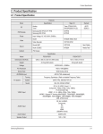
Power bd1500.1
Power bd1000.1
Power bd500.1
mono amplifier
operation & installation
Dear Customer,
Congratulations on your purchase of the world's finest brand of car audio amplifiers.
At Rockford Fosgate we are fanatics about musical reproduction at its best, and we
are pleased you chose our product. Through years of engineering expertise, hand
craftsmanship and critical testing procedures, we have created a wide range of
products that reproduce music with all the clarity and richness you deserve.
For maximum performance we recommend you have your new Rockford Fosgate
product installed by an Authorized Rockford Fosgate Dealer, as we provide
specialized training through Rockford Technical Training Institute (RTTI).
Please read your warranty and retain your receipt and original carton for possible
future use.
Great product and competent installations are only a piece of the puzzle when it
comes to your system. Make sure that your installer is using 100% authentic
installation accessories from Connecting Punch in your installation. Connecting
Punch has everything from RCA cables and speaker wire to Power line and battery
connectors. Insist on it! After all, your new system deserves nothing but the best.
To add the finishing touch to your new Rockford Fosgate image order your Rockford
wearables, which include everything from T-shirts and jackets to hats and
sunglasses.
To get a free brochure on Rockford Fosgate products and Rockford accessories, in
the U.S. call 480-967-3565 or FAX 480-967-8132. For all other countries, call
+001-480-967-3565 or FAX +001-480-967-8132.
PRACTICE SAFE SOUND™
CONTINUOUS EXPOSURE TO SOUND PRESSURE LEVELS OVER
100dB
MAY CAUSE PER-
MANENT HEARING LOSS. HIGH POWERED AUTOSOUND SYSTEMS MAY PRODUCE SOUND
PRESSURE LEVELS WELL OVER
130dB. USE COMMON SENSE AND PRACTICE SAFE SOUND.
Visit our website for the latest information on all Rockford products.
If, after reading your manual, you still have questions regarding this product, we
recommend that you see your Rockford Fosgate dealer. If you need further
assistance, you can call us direct at 1-800-669-9899. Be sure to have your serial
number, model number and date of purchase available when you call.
The serial number can be found on the outside of the box. Please record it in the
space provided below as your permanent record. This will serve as verification of
your factory warranty and may become useful in recovering your amplifier if it is
ever stolen.
Serial Number: __________________________________
Model Number:__________________________________
i
Table of Contents
Specifications ............................................................................................1
Introduction ..............................................................................................3
Amplifier Accessory Pack..........................................................................3
Amplifier Feature Chart ............................................................................4
Design Features ........................................................................................5
Installation Considerations ........................................................................7
Mounting Location....................................................................................8
Battery and Charging ................................................................................9
Wiring the System ..................................................................................10
Installation ..............................................................................................11
Troubleshooting ......................................................................................15
Warranty Information ..............................................................................17
International Information ........................................................................18
GETTING STARTED
Welcome to Rockford Fosgate! This manual is designed to provide
information for the owner, salesperson and installer. For those of you
who want quick information on how to install this product, please
turn to the Installation Section of this manual or refer to the icons
listed below. Other information can be located by using the Table of
Contents. We, at Rockford Fosgate, have worked very hard to make
sure all the information in this manual is current. But, as we are constantly finding new ways to improve our product, this information is
subject to change without notice.
Sections marked
INSTALLATION
include “slam dunk”
wiring connections
Sections marked
TROUBLESHOOTING
include recommendations for
curing installation problems
ii
Specifications
System Model
bd500.1
bd1000.1
bd1500.1
Frequency Response:
10-250Hz ± 3dB
10-250Hz ± 3dB
10-250Hz ± 3dB
Bandwidth:
10-250Hz ± 3dB
10-250Hz ± 3dB
10-250Hz ± 3dB
125mV to 2.8V
125mV to 2.8V
125mV to 2.8V
Input Sensitivity:
Protection:
Over - current protection
Battery under - over voltage protection
Thermal protection
Battery Fuse:
Input Impedance:
50 Amperes
100 Amperes
150 Amperes
20kΩ
20kΩ
20kΩ
Number of Channels:
RMS Continuous Power:
Mono Amplifier <1% THD + N
400W into 4Ω
with <1% THD
500W into 4Ω
with <1% THD
750W into 4Ω
with <1% THD
600W into 2Ω
1000W into 2Ω
1500W into 2Ω
with <1% THD
with <1% THD
with <1% THD
Signal to Noise Ratio:
90dB A-weighted
Crossover Slope:
24dB/octave Butterworth
Crossover Frequency Range:
Recommended Fuse:
50 to 250Hz
50amps*
100amps*
*recommended fuse not supplied
1
150amps*
Introduction
In R&D for 3 years, the engineers at Rockford Fosgate unveiled a new technology for car audio applications, Class bd. The principle was shown to
the public at the 1999 CES.The bd class amplifier puts over 1000 watts of
rms power in the hands of the serious car audio fanatic-- and does so in the
relatively small size of the older Power 250.1 package.
Conventional Class D amplifiers have been around for 60 years in theory
and about 30 years in practice. Judging from market acceptance, they are
not well suited for full range reproduction.
As known to scholars of this field, a system called Class BD can remove the
troublesome, rail-to-rail carrier envelope by differential subtraction in the
load. However, since each output is now an untamed full rail-to-rail
switching signal, an RFI problem was generated which has eluded solution
over the 30 years of Class bd history.
Our new version of this principle, which we call Class bd, solves this filtering problem by generating the output pulse waveform without generating the carrier frequency. This unprecedented approach is called SingleTerminal Alternating DUal Sampling Technology - or STARDUST (patent
number 6,097,249.)
Amplifier Accessory Pack
The accessory pack included with each amplifier contains the mounting
hardware necessary to secure the amp to the vehicle and to attach the end
caps to the amplifier.
•
•
•
•
•
•
•
•
•
•
•
Installation & Operation Manual
Punch Verification Certificate
(4) Amplifier mounting screws (#8 x 3/4" Phillips)
(2) Speaker Connector Set Screws (3/32" Allen)
(2) Power Connector Set Screws (1/8" Allen)
(4) Endbell Mounting Screws (9/64" Allen)
(1) Allen Wrench (1/8")
(1) Allen Wrench (9/64")
(1) Allen Wrench (3/32")
(1) Remote Punch Bass ( replacement part # WP - 2429)
(1) Remote Punch Bass bracket screws ( 4 x 7/16” Phillips )
2
Power Mono Amplifier Feature Chart
POWER AMPLIFIER
# of Channels
Stable Into: (mono)
1
2Ω
CIRCUITRY
Class bd
MEHSA1 - heat dissipating technology
TOPAZ2 - patented noise eliminating circuitry
DSM - discrete surface mount
MOSFETS - power supply & output devices
STARDUST3
FEATURES
Die Cast Heatsink
RCA Inputs - for after market radios
Pass Thru - feeds signal to aux. amp (eliminates “Y” adapters
Pwr/Spk Block Terminals
4 Gauge PWR/GND
Variable Punch Bass (0db - + 18db @ 45Hz) (remote)
Variable Xover (50Hz - 250Hz)
Crossover Slope (Butterworth) 24db/octave
bd Sync Capable
Subsonic Filter
1 Additional information on features, specifications and system designs can be
found at: www.rockfordfosgate.com
2 TOPAZ is patented under "U.S. Patent No. 5,751,823"
3 STARDUST Class bd (patent pending)
3
Design FeatureS
1. Cast Aluminum Heatsink – The cast aluminum heatsink of the Punch
amplifier dissipates heat generated by the amplifier's circuitry. The
inherent advantage of casting provides a 30% improvement of cooling
over conventional extrusion heatsink designs.
2. Speaker Terminals – The heavy duty, gold-plated terminal block connectors (+ and –) will accept wire sizes from 8 AWG to 18 AWG. These
gold-plated connectors are immune to corrosion that can cause signal
deterioration.
3. B+ and GND Terminals – The heavy duty, gold-plated terminal block
connectors (B+ and GND) will accept wire sizes from 4 AWG to 12
AWG. These gold-plated connectors are immune to corrosion that can
cause signal deterioration.
4. REM Terminal – This spade terminal is used to remotely turn-on and
turn-off the amplifier when +12V DC is applied.
5. RCA Input Jacks – The industry standard RCA jacks provide an easy
connection for signal level input. They are gold-plated to resist the signal degradation caused by corrosion.
4
Design Features (Cont’d.)
6. RCA Pass-Thru Jacks – The Pass-Thru provides a convenient source for
daisy-chaining an additional amplifier without running an extra set of
RCA cables from the front of the vehicle to the rear amplifier location.
7. Gain Control – The input gain control is preset to match the output of
most source units. It can be adjusted to match output levels from a
variety of source units.
8. Remote Punch Bass - The Punch Bass control helps correct for acoustical deficiencies in the listening environment by helping reproduce full
range sound without excessive boost. The Punch Bass control is a narrow band adjustment centered at 45Hz variable from 0db to + 18db.
Connection is made with a cable using RJ - 45 and can be installed
under the dash for remote access.
9. Variable Crossover – The amplifiers have a built-in 24dB/octave
Butterworth filter with a crossover point variable from 50Hz to 250Hz.
The crossover can be set to Low-Pass (LP).
10. Power Indicator – The red logo on top illuminates when the unit is
turned on.
11. Protect LED - The (red) LED illuminates when the unit is latched into
protection. It requires momentary AP removal to enable output PWM.
12. bd Sync Cable - The amplifiers have a 6 pin mini DIN connector.
When operating two amplifiers in the bridge mode, the SYNC cable
must be used. This will allow the two independent frequency carrier
generators in each unit to be synchronized.
13. Subsonic Filter - A high pass filter designed to prevent frequencies
below the audio range from being applied to the core of the amplifier.
Consequently, improving loud speaker performance and power handling.
5
Installation Considerations
This section focuses on some of the vehicle considerations for installing
your new Punch amplifier. Checking your battery and present sound system, as well as pre-planning your system layout and best wiring routes, will
save installation time. When deciding how to lay out your new system, be
sure that each component will be easily accessible for making adjustments.
Before beginning any installation, be sure to follow these simple rules:
1. Be sure to carefully read and understand the instructions before attempting to install the amplifier.
2. For safety, disconnect the negative lead from the battery prior to beginning the installation.
3. For easier assembly, we suggest you run all wires prior to mounting
your amplifier in place.
4. Route all of the RCA cables close together and away from any high current wires.
5. Use high quality connectors for a reliable installation and to minimize
signal or power loss.
6. Think before you drill! Be careful not to cut or drill into gas tanks, fuel
lines, brake or hydraulic lines, vacuum lines or electrical wiring when
working on any vehicle.
7. Never run wires underneath the vehicle. Running the wires inside the
vehicle provides the best protection.
8. Avoid running wires over or through sharp edges. Use rubber or plastic grommets to protect any wires routed through metal, especially the
firewall.
9. ALWAYS protect the battery and electrical system from damage with
proper fusing. Install a fuseholder and appropriate fuse on the +12V
power wire within 18” (46 cm) of the battery terminal.
10. When grounding to the chassis of the vehicle, scrape all paint from the
metal to ensure a good, clean ground connection. Grounding connections should be as short as possible and always be connected to metal
that is welded to the main body, or chassis, of the vehicle.
6
Mounting Location
The mounting location and position of your amplifier will have a great
effect on its ability to dissipate the heat generated during normal operation.
The design of our cast aluminum heatsink serves to easily dissipate the heat
generated over a wide range of operating conditions. However, to maximize the performance of your amplifier, care should be taken to ensure adequate ventilation.
Trunk Mounting
Mounting the amplifier vertically on a surface with the fin grooves running
up and down will provide the best cooling of the amplifier.
Mounting the amplifier on the floor of the trunk will work but provides less
cooling capability than vertical mounting.
Mounting the amplifier upside down to the rear deck of the trunk will not
provide proper cooling and will severely affect the performance of the
amplifier and is strongly not recommended.
Passenger Compartment Mounting
Mounting the amplifier in the passenger compartment will work as long as
you provide a sufficient amount of air for the amplifier to cool itself. If you
are going to mount the amplifier under the seat of the vehicle, you must
have at least 1" (2.54cm) of air gap around the amplifier's heatsink.
Mounting the amplifier with less than 1" (2.54cm) of air gap around the
amplifier's heatsink in the passenger compartment will not provide proper
cooling and will severely affect the performance of the amplifier and is
strongly not recommended.
Engine Compartment Mounting
Rockford Fosgate amplifiers should never be mounted in the engine compartment. Not only will this void your warranty but could create an embarrassing situation caused by the ridicule from your friends.
7
Battery and Charging
Amplifiers will put an increased load on the vehicle's battery and charging
system. We recommend checking your alternator and battery condition to
ensure that the electrical system has enough capacity to handle the
increased load of your stereo system. Stock electrical systems which are in
good condition should be able to handle the extra load of any Rockford
amplifier without problems, although battery and alternator life can be
reduced slightly. To maximize the performance of your Rockford Fosgate
amplifier, we suggest the use of a heavy duty battery and an energy storage
capacitor.
Wiring the System
CAUTION: Avoid running power wires near the low level input cables,
antenna, power leads, sensitive equipment or harnesses. The power wires
carry substantial current and could induce noise into the audio system.
1. Plan the wire routing. Take care when running signal level RCA cables
to keep them close together but isolated from the amplifier's power
cables and any high power auto accessories, especially electric motors.
This is done to prevent coupling the noise from radiated electrical
fields into the audio signal. When feeding the wires through the firewall or any metal barrier, protect them with plastic or rubber grommets
to prevent short circuits. Leave the wires long at this point to adjust for
a precise fit at a later time.
2. Prepare the Power cable for attachment to the amplifier by stripping
5/8" of insulation from the end of the wire. The use of 8 gauge power
cable can interfere with the installation of the end caps. Proper wire
dress can prevent this from occurring. To prevent the wire from fraying,
strip the insulation at a 45° angle. Insert the bared wire into the B+ terminal with the long side of the insulation on the top. Bend the cable
down at a 90° angle. Tighten the set screw to secure the cable in place.
8
Wiring the System
3. Strip 3/8" from the battery end of the power cable and crimp a large ring
terminal to the cable. Use the ring terminal to connect to the battery positive terminal. Do not install the fuse at this time.
4. Prepare a length of cable to be used for the ground connection. Strip
5/8" of insulation from the end of the cable as described above and connect to the appropriate terminal of the amplifier. Prepare the chassis
ground by scraping any paint from the metal surface and thoroughly
clean the area of all dirt and grease. Strip the other end of the wire and
attach a ring connector. Fasten the cable to the chassis using a nonanodized screw and a star washer.
5. Prepare the REM turn-on wire for connection to the amplifier by stripping
1/4" of insulation from the wire end and crimping an insulated spade
connector in place. Slide the connector over the REM terminal on the
amplifier. Connect the other end of the REM wire to a switched 12 volt
positive source. The switched signal is usually taken from the source
units auto antenna or the accessory lead. If the source unit does not have
these outputs available, the recommended solution is to wire a mechanical switch in line with a 12 volt source to activate the amplifier.
6. Securely mount the amplifier (with supplied screws) to the vehicle or
amp rack. Be careful not to mount the amplifier on cardboard or plastic
panels. Doing so may enable the screws to pull out from the panel due
to road vibrations or sudden vehicle stops.
7. Determine the number of inputs needed to drive the amplifier and move
the input switch to the desired setting (Power 400 & Power 800 4-channel amplifiers only.).
8. Connect the source signal to the amplifier by plugging the RCA cables
into the input jack(s) at the amplifier.
9. Connect the speakers. Strip the speaker wires 5/8" and insert into the
appropriate terminal on the amplifier. Insert the bare wire into the speaker terminal and tighten the set screw to secure into place. Be sure to
maintain proper speaker polarity. DO NOT chassis ground any of the
speaker leads, as unstable operation may result.
10. Perform a final check of the completed system wiring to ensure that all
connections are accurate. Check all power and ground connections for
frayed wires and loose connections which could cause problems from
road vibrations.
11. When bridging two BD110001/BD15001 units you must use the BDSYNC
cable, available at your local dealer. The speaker grounds of both units
must be joined using an 8 gauge wire that is no longer than 15”.
9
Installation
Power Connections
Mono Mode
• RCA inputs are connected to both left and right inputs
• Speaker Impedance should be 2Ω minimum
10
Crossover Operation
• Variable Crossover can be set from 50Hz and 250Hz Low-Pass (LP) only
Punch Bass Operation
+24
+18
+12
+6
+3
0dB
• Carefully increase potentiometer to add Punch to your bass frequencies
• Exercise caution when increasing Punch Bass. Maximum boost can cause
potential woofer damage caused by overexcursion
11
Pass-Thru
• Pass-Thru feeds signal to secondary amplifier
• Signal from Pass-Thru remains stereo
12
(use bd sync kit)
Connect the two NEG Speaker outputs together using an eight gauge wire no longer than 15”.
When bridging 2 units together, Unit 1 PHASE must be set at 0, Unit 2 PHASE must be set at 180.
Unit 1 (PHASE set at 0) Connect (+) terminal to (+) Speaker terminal.
Unit 2 (PHASE set at 180) Connect (+) terminal to (-) Speaker terminal.
When bridged do not exceed minimum impedance of 4Ω.
Bridging Mode
13
•
•
•
•
•
Troubleshooting
If you are having problems after installation follow the
Troubleshooting procedures below.
Procedure 1: Check Amplifier for proper connections.
Verify that POWER light is on. If POWER light is on skip to Step 2, if not continue.
1. Check in-line fuse on battery positive cable. Replace if necessary.
2. Verify that Ground connection is connected to clean metal of the vehicle’s
chassis. Repair/replace if necessary.
3. Verify there is 10.5 - 15.5 Volts of current present at the positive battery and
remote turn-on cable. Verify quality connections for both cables at amplifier,
stereo, and battery/fuseholder. Repair/replace if necessary.
Procedure 2: Check Amplifier for audio output.
1. Connect a single 4 or 8 ohm test speaker directly to each output channel
amplifier. Verify speakers in car are good and wiring between amplifier and
speakers, including connectors are good. Repair/replace if necessary.
2. Verify good RCA/high-level input connections at stereo and amplifier. Check
entire length of cables for kinks, splices, etc. Test RCA/high-level inputs for AC
current with stereo on. Repair/replace if necessary.
3. Disconnect RCA/high-level input from amplifier. Connect RCA/high-level input
from test stereo directly to amplifier input.
Procedure 3: Check Amplifier if you experience Turn-on Pop.
1. Disconnect input signal to amplifier and turn amplifier on and off.
2. If the noise is eliminated, connect the REM lead of amplifier to source unit with
a delay turn-on module.
OR
1. Use a different 12 Volt source for REM lead of amplifier (i.e. battery direct).
2. If the noise is eliminated, use a relay to isolate the amplifier from noisy turn-on
output.
Procedure 4: Check Amplifier if you experience excess Engine Noise.
1. Route all signal carrying wires (RCA, Speaker cables) away from power and
ground wires.
OR
2. Bypass any and all electrical components between the stereo and the amplifier(s). Connect stereo directly to input of amplifier. If noise goes away the unit
being bypassed is the cause of the noise.
OR
3. Remove existing ground wires for all electrical components. Reground wires to
different locations. Verify that grounding location is clean, shiny metal free of
paint, rust etc.
OR
4. Add secondary ground cable from negative battery terminal to the chassis
metal or engine block of vehicle.
OR
5. Have alternator and battery load tested by your mechanic. Verify good working order of vehicle electrical system including distributor, spark plugs, spark
plug wires, voltage regulator etc.
14
Limited Warranty Information
Rockford Corporation offers a limited warranty on Rockford Fosgate products on the
following terms:
• Length of Warranty
3 years on electronics-90 days on electronic B-stock (receipt required)
1 years on source units
1 year on speakers-90 days on speaker B-stock (receipt required)
• What is Covered
This warranty applies only to Rockford Fosgate products sold to consumers by
Authorized Rockford Fosgate Dealers in the United States of America or its possessions. Product purchased by consumers from an Authorized Rockford Fosgate
Dealer in another country are covered only by that country’s Distributor and not
by Rockford Corporation.
• Who is Covered
This warranty covers only the original purchaser of Rockford product purchased
from an Authorized Rockford Fosgate Dealer in the United States. In order to
receive service, the purchaser must provide Rockford with a copy of the receipt
stating the customer name, dealer name, product purchased and date of purchase.
• Products found to be defective during the warranty period will be repaired or
replaced (with a product deemed to be equivalent) at Rockford's discretion.
• What is Not Covered
1. Damage caused by accident, abuse, improper operations, water, theft
2. Any cost or expense related to the removal or reinstallation of product
3. Service performed by anyone other than Rockford or an Authorized Rockford
Fosgate Service Center
4. Any product which has had the serial number defaced, altered, or removed
5. Subsequent damage to other components
6. Any product purchased outside the U.S.
7. Any product not purchased from an Authorized Rockford Fosgate Dealer
• Limit on Implied Warranties
Any implied warranties including warranties of fitness for use and merchantability are limited in duration to the period of the express warranty set forth above.
Some states do not allow limitations on the length of an implied warranty, so this
limitation may not apply. No person is authorized to assume for Rockford
Fosgate any other liability in connection with the sale of the product.
• How to Obtain Service
Please call 1-800-669-9899 for Rockford Customer Service. You must obtain an
RA# (Return Authorization number) to return any product to Rockford Fosgate.
You are responsible for shipment of product to Rockford.
Ship to: Speakers
Rockford Acoustic Design
(Receiving-speakers)
609 Myrtle N.W.
Grand Rapids, MI 49504
RA#:_________________
Ship to: Electronics
Rockford Corporation
Warranty Repair Department
2055 E. 5th Street
Tempe, AZ 85281
RA#:_________________
15
International Information
ESPAÑOL
LEA DETENIDAMENTE LAS SIGUIENTES INSTRUCCIONES DE INSTALACION DEL PRODUCTO. EVITARA POSIBLES DAÑOS A VD., AL VEHICULO O AL PRODUCTO.
INTRODUCCION
Los ingenieros de Rockford han diseñado los amplificadores Power para
ofrecer en el dificil entorno de un automóvil una calidad de sonido superior en un producto flexible, fiable y eficiente. Trans•ana es un circuito de
baja tensión en la etapa de preamplificación de los amplificadores Power
que permite que la musica suene limpia y cristalina y muy real, incluso a
altos niveles de audicion. Esto se complementa con el TOPAZ, un circuito
exclusivo de masa utilizado para eliminar los ruidos asociados con las
instalaciones de car-audio. La flexibilidad esta garantizada con el uso de la
XCard incorporada. La fiabilidad se refuerza con el uso de un circuito de
proteccion llamado NOMAD, mientras que los MOSFET y la tecnologia
DSM (montaje discreto en superficie) aumentan la eficiencia del amplificador. La combinacion de todos estos componentes dan al amplificador
Power una impresionante calidad de sonido en un chasis discreto. Mas adelante encontrará mas explicaciones de todas estas tecnologías, la mayoria
de ellas usados en exclusiva y patentadas por Rockford.
UBICACIÓN PARA EL MONTAJE
Montaje en el Malatero
Monte el amplificador verticalmente con las lineas del radiador orientadas
de arriba hacia abajo. De esta manera conseguira la mejor ventilacion.
Montaje en el Compartimento de Pasajeros
El montaje en el compartimento de pasajeros sera eficiente en funcion de
la ventilacion que tenga el amplificador. Si va a instalar el amplificador bajo
un asiento deberá dejar al menos 2.5cm libres sobre la carcasa del amplificador.
Instalacion
Por seguridad, desconecte el terminal negativo de la bateria antes de
comenzar la instalacion.
16
Terminal B+
El cable B+ debe ir provisto de un fusible a una distancia no mayor de 45cm
de la bateria. Prepare el cable e instale el portafusibles en el compartimento del motor. Las conexiones han de ser impermeables.
Terminal GND
Prepare un trozo de cable para usarlo como toma de masa. Prepare un
punto de masa en el chasis rascando y eliminando la pintura de la superficie de metal y limpielo de toda suciedad asegure el cable al chasis con un
tornillo.
Terminal REM
Conecte el cable REM a un punto de +12V con mutable. La señal se suele
coger de la salida auto antena del radio cassette si este no tiene salida
remote.
Funcionamiento Mono
• Las entradas RCA se conectan a ambos canales izquierdo y
derecho
• La impedancia minima mono debe ser 2Ω.
• Los Divisores de Frecuencia Variable pueden ser ajustados
para Rango Completo (FULL) ó Pasa-Bajos (LP) entre 50 Hz
y 250Hz.
17
FRANÇAIS
ATTENTION: Veuillez lire les instructions suivantes pour l'installation de
cet amplifcateur. Ne pas les suivre pourrait causer des blessures ou
endommager le véhicule.
INTRODUCTION
Les ingénieurs de Rockford Fosgate ont conçu l'amplificateur Power pour
supporter l'environnement rude de l'automobile en délivrant une qualité de
son supérieure dans un ensemble efficace, fiable et flexible. Trans•ana est
un circuit de bas voltage dans l'étage de préamplification de tous les ampificateurs Power qui reproduit un son musical clair comme du cristal et très
réel, même à très haut volume. Ceci est accompagné du TOPAZ, un circuit
unique employé pour éliminer les problèmes de bruits parasites associés
aux systémes audiomobile et leur installation. La flexibilité est assurée par
l'emploi d'une XCard incorporée.
La fiabilité est garantie grâce au circuit de protection NOMAD, la technologie MOSFET et DSM (Composants Montés en Surface) améliorent l'efficacité de l'amplificateur.
L'ensemble de ces atouts donne à l'amplificateur Power une qualité de son
inégalable sous une carrosserie “pare-balles.”
Vous trouverez de plus amples informations sur ces technologies, exclusivement conçues et brevetées par Rockford, dans la rubrique technique.
MONTAGE
Montage dans le coffre
Monter l'amplificateur verticalement avec les rainures de haut en bas ce qui
lui permet de refroidir plus facilement.
Montage dans l'habitacle
Monter l'amplificateur dans l'habitacle ne pose aucun problème, du
moment qu'il y ait assez d'air pour le refroidir. Si vous montez l'ampli en
dessous du siège, prévoyez 3 cm d'air autour du radiateur.
Installation
Pour votre sécurité, déconnectez la borne négative de la batterie du
véhicule avant de commencer l'installation.
18
Terminal B+
Il est impératif qu'il y ait un fusible sur le câble pour la connexion à la
masse. Préparez le châssis en grattant la peinture de la surface métallique
et nettoyez la saleté et l'huile. Attachez le câble au châssis avec une vis.
Terminal GND
Préparez une longueur de câble pour la connexion à la masse. Préparez le
châssis en grattant la peinture de la surface métallique et nettoyez la saleté
et l'huile. Attachez le câble au châssis avec une vis.
Terminal REM
Connectez le fil REM à une commande 12 volts positive de la source. La
commande 12 volts est habituellement prise sur la sortie antenne électrique
de la source ou la commande accessoire. Si la source ne dispose pas de ces
sorties, nous vous recommandons d'installer un interrupteur qui fournira un
positif 12 volts au REM de l'amplificateur.
Opération mono
• Les entrées RCA sont connectées aux canaux gauche et droit
• L'impédance du canal mono devrait être de minimum 2Ω
• Filtre actif, position (full) sans action, ou passe-bas (LP) réglabe
entre 50Hz et 250Hz.
19
DEUTSCH
BITTE LESEN SIE DIESE GEBRAUCHSANLEITUNG ZUERST SORGFÄLTIG
DURCH. DAS KANN SIE VOR DEM FALSCHEN EINSATZ, AUSFALLEN
ODER SOGAR BESCHÄDIGUNG DES PRODUKTES ODER IHRES
FAHRZEUGES SCHÜTZEN.
EINLEITUNG
Rockford Ingenieure haben die Power Verstärker entwickelt. Mit höchstem
Technologie-Standart, hervorragender Klangqualität, einfacher Handhabung
und bester Servicefreundlichkeit Trans•ana ist eine Nieder-Volt Schaltung im
Vorverstärkerteil aller Power Verstärker die für kristallklaren Klang auch bei
sehr hohen Lautstärken sorgt. TOPAZ, eine einzigartige Erdungsschaltung
verhindert und unterdrückt Einstreuungen und Störungen die nur allzu oft
Car Audio Systeme beeinträchtigen. Flexibilität durch die Vielfalt der
Aktivweiche mit ihren XCards, lange Lebensdauer durch die
Schutzschaltung NOMAD und der Einsatz von MOSFET Transistoren und
DSM (Discrete Surface Mount), machen diese Verstärker so effizient. Das
Ergebnis all dieser Komponenten machen Power-Verstärker so einzigartig
und in ihrer Klangqualität nahezu unschlagbar. Eine genauere Beschreibung
dieser Technologien, die gröbtenteils einzigartig und von Rockford patentiert
sind, finden Sie unter Technical Design Features.
EINBAUORT
Im Fahrzeugkofferraum
Der vertikale Einbau der Endstufen, das bedeutet, dab die Kühlrippen von
oben nach unten verlaufen, gibt dem Verstärker die beste Kühlung.
Auf der Beifahrerseite
Sollte der Verstärker auf der Beifahrerseite montiert werden, so ist es sehr
wichtig, für eine ausreichende Kühlung zu sorgen. Sollte der Verstärker z.B.
unter dem Beifahrersitz montiert werden, sollte dem Kühlkörper mindestens
ein Luftspalt von 3 cm bleiben, um so für eine ausreichende Kühlung zu
sorgen.
Einbau
Zur Sicherheit klemmen Sie den Negativ-Pol der Batterie während des
gesamten Einbaues ab.
20
B+ Anschlub
Die Plus-Leitung MUb ca. 40 cm nach dem Plus-Pol der Batterie
abgesichert sein. Preparieren Si die Kabellängen und montieren Sie den
Sicherungshalter im Motorraum. ALLE Verbindungen müssen wasserdicht
sein.
GND Anschlub
Preparieren Sie Ihr Kabel für die Negativ Leitung (Erdung). Preparieren Sie
die Anschlubstelle des Erdungskabels, indem Sie das Metall gründlich reinigen und vom Lack befreien. Befestigen Sie nun die Erdung an dieser Stelle
mit einer Schraube.
REM Anschlub
Verbinden Sie das Ein-und Ausschaltungskontroll-Kabel mit Ihrem Radio
(12 Volt positiv). Normalerweise verwenden Sie hierfür die Ant.-Remote
Ihres Radios oder ein eigens dafür vorgesehenes Kabel (Amp-Remote).
Sollte Ihr Radio diesen Anschlub nicht besitzen, so verwenden Sie eine 12
Volt Spannung, die Sie durch einen Schalter ein- und ausschalten können.
Mono Operation
• Chinch Eingänge des rechten- und linken-Kanales anschlieben
• Die Impedanz des Mono Kanales sollte minimum 2 Ohm
betragen
• Die variable Weiche kann den vollen Frequenzbereich übertragen (Full) oder auf Tiefpass (LP) eingestellt werden, regelbar
zwischen 50Hz und 250Hz.
21
ITALIANO
ATTENZIONE: SI PREGA DI LEGGERE LE SEGUENTI ISTRUZIONI PER
L'INSTALLAZIONE DI QUESTO PRODOTTO. IL NON SEGUIRLE
POTREBBE RISULTARE SERIAMENTE DANNOSO PER LA PERSONA O
PER IL VEICOLO.
INTRODUZIONE
Gli ingenieri Rockford hanno progettato la serie di amplificatori Power per
resistere all'ostico ambiente automobilistico mentre suonano con una musicalitá superiore, offrendo un insieme versatile, affidabile ed efficiente.
Trans•ana é un circuito a bassa tensione dello stadio preamplificatore del
Power che permette al suono di essere cristallino e reale anche in presenza di volumi molto elevati…tutto questo é accoppiato TOPAZ, un exclusivo circuito di massa impiegato per eliminare i problemi di rumore comunemente presenti negli impianti car audio. Il massimo della versatilitá é raggiunto con l'impiego delle XCard. L'affidabilitá é completamente garantita
dall'impiego di un circuito di protezione chiamato NOMAD, mentre l'uso
di MOSFET e della tecnologia DSM (Discrete Surface Mount) permette di
raggiungere efficienze elevatissime. Il risultato finale di tutte queste tecnnologie moderne é che gli amplificatori Power suonano meravigliosamente
e sono indistruttibili, a “prova di proiettile.” Una spiegazione di queste tecnologie innovative, molte coperte da brevetti Rockford, sono descritte in
un'altra sezione di questo manuale.
DOVE POSIZIONARLO
Nel Bagagliaio
Montando l'amplificatore su una superficie in verticale con le alette
direzionate dall'alto verso il basso si garantirá un miglior raffreddamento
dell'amplificatore.
Nell'abitacolo
Montare l'amplificatore nell'abitacolo si avrá un funzionamento regolare se
si garantisce un flusso d'aria sufficiente. Per l'installazione sotto un sedile, é
necessario avere uno spazio di almeno 3 cm attorno a tutto l'amplificatore.
Installazione
Per sicurezza, scollegare il polo negativo della batteria dell'auto prima di
iniziare l'installazione.
22
Terminale B+ (cavo positivo)
Il cavo positivo deve essere protetto da un fusibile a non piú di 45 cm dalla
batteria. Terminare il cavo e installare il fusibile nel vano motore. Tutte le
connessioni devono essere a prova d'acqua.
Terminale GND (cavo negativo)
Decidere la lunghezza del cavo e terminarlo. Preparare la massa grattando
la vernice dal telaio dell'auto ed eliminando tracce di olio o sporco. Fissare
il cavo di massa al telaio con una vite.
Terminale REM (Consenso di accensione)
Collegare il cavo REM ad un positivo presente solo ad autoradio accesa
(normalmente il cavo pilota dell'antenna elettrica o il cavo accessori dell'autoradio). Se la sorgente non dovesse essere equipaggiata con queste
uscite, la soluzione raccomandabile é di inserire un interruttore su un cavo
positivo e connettersi all'amplificatore.
Mono Operation
• Ingressi RCA collegati sia al canale destro sia al sinistro
• L'impedenza per il canale mono deve essere minimo 2Ω
• Il crossover regolabile puó essere impiegato a gamma intera,
Full Range, (FULL) o come passa-basso (LP) regolabile da
50Hz a 250Hz.
23
Notes
24
MADE IN THE USA
This product is designed, developed and assembled in the
USA by a dedicated group of American workers. The majority
of the components used in the construction of this product are
produced by American companies. However, due to the global nature of their manufacturing facilities and the loudspeaker
parts industry in general, some parts may be manufactured in
other countries.
®
®
Rockford Corporation
546 South Rockford Drive
Tempe, Arizona 85281 U.S.A.
In U.S.A., (480) 967-3565
In Europe, Fax (49) 8503-934014
In Japan, Fax (81) 559-79-1265
9/00 M.J.T
MAN-3154-B


![2649 Manuals . . . . . . . . . . . . . . . . . . . . . . . . . . C. ClarWDTD [24]](http://vs1.manualzilla.com/store/data/005876281_1-ca0a669885d1d1e5f63e9b5ff82f3016-150x150.png)