1
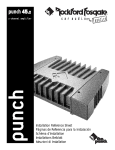
360.6
punch
t r a n s • a n a
®
®
car audio
for
fanatics
6-Channel Amplifier
Operation & Installation
®
Dear Customer,
Congratulations on your purchase of the world's finest brand of car audio amplifiers.
At Rockford Fosgate we are fanatics about musical reproduction at its best, and we are
pleased you chose our product. Through years of engineering expertise, hand craftsmanship and critical testing procedures, we have created a wide range of products that
reproduce music with all the clarity and richness you deserve.
For maximum performance we recommend you have your new Rockford Fosgate
product installed by an Authorized Rockford Fosgate Dealer, as we provide specialized
training through Rockford Technical Training Institute (RTTI). Please read your
warranty and retain your receipt and original carton for possible future use.
Great product and competent installations are only a piece of the puzzle when it comes
to your system. Make sure that your installer is using 100% authentic installation
accessories from Connecting Punch in your installation. Connecting Punch has
everything from RCA cables and speaker wire to Power line and battery connectors.
Insist on it! After all, your new system deserves nothing but the best.
To add the finishing touch to your new Rockford Fosgate image order your Rockford
wearables, which include everything from T-shirts and jackets to hats and sunglasses.
To get a free brochure on Rockford Fosgate products and Rockford accessories, in the
U.S. call 602-967-3565 or FAX 602-967-8132. For all other countries, call +001-602967-3565 or FAX +001-602-967-8132.
PRACTICE SAFE SOUND™
CONTINUOUS EXPOSURE TO SOUND PRESSURE LEVELS OVER
100dB
MAY CAUSE PERMANENT HEARING LOSS. HIGH
POWERED AUTOSOUND SYSTEMS MAY PRODUCE SOUND
PRESSURE LEVELS WELL OVER
130dB. USE COMMON SENSE
AND PRACTICE SAFE SOUND.
If, after reading your manual, you still have questions regarding this product,
we recommend that you see your Rockford Fosgate dealer. If you need further
assistance, you can call us direct at 1-800-795-2385. Be sure to have your serial
number, model number and date of purchase available when you call.
The serial number can be found on the outside of the box. Please record it in
the space provided below as your permanent record. This will serve as
verification of your factory warranty and may become useful in recovering your
amplifier if it is ever stolen.
Serial Number: ________________________________
Model Number: ________________________________
TABLE
OF
CONTENTS
Introduction ............................................................................................. 1
Punch Amplifier Accessory Pack .............................................................. 1
Technical Design Features ....................................................................... 2
360.6 Design Features .............................................................................. 5
Installation Considerations ....................................................................... 7
Mounting Location ................................................................................... 8
Battery and Charging ................................................................................ 9
Wiring the System .................................................................................... 9
Using the XCard ..................................................................................... 12
Customizing the XCard .......................................................................... 12
Resistor Chart ......................................................................................... 13
XCard Configurations ............................................................................. 14
Using the Phase Switch .......................................................................... 16
Using the Signal Switching Network ...................................................... 17
360.6 Installation ................................................................................... 25
System Diagrams .................................................................................... 31
Troubleshooting ..................................................................................... 35
Dynamic Power Measurements .............................................................. 38
Specifications ......................................................................................... 40
Warranty Information ............................................................................. 41
International Information........................................................................ 42
G E T T I N G STA R T E D
Welcome to Rockford Fosgate! This manual is designed to provide
information for the owner, salesperson and installer. For those of you
who want quick information on how to install this product, please turn
to the Installation Section of this manual or refer to the icons listed
below. Other information can be located by using the Table of Contents.
We, at Rockford Fosgate, have worked very hard to make sure all the
information in this manual is current. But, as we are constantly finding
new ways to improve our product, this information is subject to change
without notice.
a
d
v
a
n
c
e
d
O
p
e
r
a
t
i
o
n
Sections marked
ADVANCED OPERATION
include in-depth
technical information
®
®
I
N
S
T
A
L
L
A
T
I
O
N
Sections marked
INSTALLATION
include “slam dunk”
wiring connections
TROUBLE-S
H
O
O
T
I
N
G
Sections marked
TROUBLESHOOTING
include recommendations
for curing
installation problems
INTRODUCTION
The Punch 360.6, is a 360 watt, 6 channel amplifier with integrated
features for accommodating “single amplifier” system designs. Built
into the amplifier are four internal XCards and a Signal Switching
Network. These features simplify signal processing and enable
custom signal distribution for each set of channels. Also integrated is
a Phase Switch and Bass EQ circuit designed to improve system
tuning. The engineering effort applied to the Punch 360.6 amplifier
represents how an impressive 3-way system can be easily installed
while keeping the components used to a minimum.
A CCESSORY P ACK
Installation & Operation Manual
Punch Verification Certificate
(4) Amplifier mounting screws (#8 x 3/4" Phillips)
(16) Speaker & power connector screws (3/32" Allen)
(4) End cap mounting screws (9/64" Allen)
(1) Allen Wrench 9/64"
(1) Allen Wrench 3/32"
(1) AGU Fuseholder
(1) AGU 50 Amp Fuse
–1–
T ECHNICAL D ESIGN F EATURES
◆ TRANS•ANA
(TRANSconductance Active Nodal Amplifier)
The TRANS•ANA (TRANSconductance Active Nodal Amplifier) is a
circuit that allows the audio signal to pass through the amplifier at low
voltage. The signal is directly level-shifted to the fixed high voltage
rails via a pair of driver transistors. Signal linearity is assured by an
active node formed by the drive transistors at ultrasonic frequencies.
This allows amplifier performance similar to trans•nova which is
highly stable and linear while utilizing the advantages of a nonfloating power supply.
THE RESULT: An extended frequency bandwidth accurately supplied
to the output stages of the amplifier.
◆ TOPAZ (Tracking Operation Pre-Amplifier Zone)
The TOPAZ (Tracking Operation Pre-Amplifier Zone) circuitry solves
ground loop noise problems common to automotive amplifier design.
This innovative new development allows vastly improved isolation of
the input signal grounds from the power supply ground of the
amplifier. This is accomplished by allowing the source unit to control
the potential “environment” of the entire input structure or “zone” of
the amplifier. This process improves the noise rejection of the amplifier by 30-40dB – an astounding 30-100 times better than amplifiers
without TOPAZ.
THE RESULT: Elimination of troublesome ground loop noise between
source and amplifier.
◆ Bass EQ
The Bass EQ helps correct for acoustical deficiencies in the listening
environment. A unique potentiometer that controls bass compensates for the lack of low frequencies present in most car environments. Unlike a conventional tone control, the Bass EQ corrects the
specific problem of poor low bass response.
THE RESULT: Provides better low bass response.
–2–
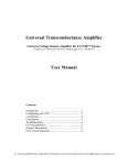
◆ DSM (Discrete Surface Mount) Technology
The DSM (Discrete Surface Mount) manufacturing process combines
the advantages of both discrete components and integrated circuitry.
Rockford Fosgate is the only American amplifier manufacturer to have
invested millions into this process. DSM components differ from
conventional discrete components in different ways. They are more
compact, more rugged, and they efficiently dissipate generated heat.
Using them wherever appropriate allows the advantages associated
with discrete circuitry to be retained while also providing room for
both highly advanced processing features and generous PC board
copper paths where needed. Their short lead-out structures allow
maximum audio performance and highest signal-to-noise ratios to be
obtained in amplifiers of desirable package size without resorting to
“amplifier-on-a-chip” shortcuts. These advantages are shown below
in Figure 1.
Figure 1
Component
Solder
PC
Board
Solder
PC
Board
Thru-Hole
Surface Mount
THE RESULT: Fewer connections, improved reliability, shorter signal
paths, superior signal-to-noise ratio and awesome sonic performance.
◆ XCard (Internal Crossover)
The Punch amplifiers utilize internal active crossovers. These crossovers have many performance advantages such as using discrete
components for exact frequency adjustments which are far superior to
potentiometers. Additionally, the XCard can be configured for highpass, low-pass and full range operation. With slight modifications,
many crossover frequencies and slope configurations can be achieved.
THE RESULT: Increased system design flexibility with a precise
electronic crossover without the limitations of conventional potentiometer designs.
–3–
◆ MOSFET Devices
Rockford Fosgate is one of the few manufacturers in the sound
community to utilize MOSFET devices in both the power supply and
the output stages. MOSFET (Metal Oxide Semiconductor Field Effect
Transistor) devices offer several important inherent advantages over
the 30 year old technology of bi-polar design. These advantages
include: thermal stability, switching speed, ultra low output impedance and wider bandwidth linearity. In addition, MOSFETs operate
very similarly to vacuum tubes in which they are more linear than bipolar transistors. However, MOSFETs can deliver the midrange clarity
without the limitations of transient response and high frequency
phase shifting normally associated with tube operation.
THE RESULT: Operational characteristics similar to vacuum tubes
without the performance limitations of tube design.
◆ NOMAD (NOn-Multiplying Advanced Decision)
The Punch amplifiers use an analog computer process to maximize
safe output power under all operating conditions. The innovative
NOMAD (NOn-Multiplying Advanced Decision) system is the most
sophisticated version of this technique ever used, bringing previously
unavailable levels of accuracy, stability, temperature immunity and
reliability to this critical process. NOMAD makes advanced decisions based on device voltages to precisely control the awesome
levels of current available in the output MOSFETs to safe values – but
only when absolutely needed.
THE RESULT: Extremely fast protection system that always protects
the amplifier and never degrades the sound.
◆ Signal Switching Network
The Signal Switching Network allows the RCA input signals to be
distributed to the amplifier channels in multiple configurations.
Among the many possible configurations, a setting called E-Z bridge
uses a single RCA (L mono) and gain (L) control to feed a pair of
channels, thus simplifying the bridging process.
THE RESULT: Allows input signals to be distributed to amplifier
channels in many different configurations.
–4–
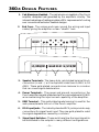
360.6 D ESIGN F EATURES
1. Cast Aluminum Heatsink – The cast aluminum heatsink of the Punch
amplifier dissipates heat generated by the amplifier's circuitry. The
inherent advantage of casting provides a 30% improvement of cooling
over conventional extrusion heatsink designs.
2. End Caps – The unique end caps conceal the wiring and input
cables, giving the amplifier a clean “stealth” look.
R
R
R
LED
+
L
–
Ch. C Ch. C
Bass EQ Gain L
Ch. C
12 9 8
3
–
L
+
–
Ch. B
R
+
REM
Ch. B
Dual B+
+
Ch. A
Gain
Dual GND
8
+
L
3
–
+
Ch. A
5
4
R –
Ch. C
Ch. A
6
Ch. B
3
Ch. B
Gain
L
L
Ch. C
R
–
Ch. A
3
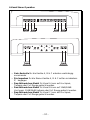
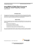
3. Speaker Terminals – The heavy duty, gold-plated terminal block
connectors (+ and –) will accept wire sizes from 8 AWG to 18
AWG. These gold-plated connectors are immune to corrosion
that can cause signal deterioration.
4. Power Terminals – The power and ground connectors on the
Punch amplifier are gold-plated and will accommodate up to 8 AWG
wire maximizing the input current capability of the amplifier.
5. REM Terminal – This gold-plated spade terminal is used for the
auto power/remote turn on of the Punch amplifier.
6. RCA Input Jacks – The industry standard RCA jacks provide easy
connections for signal level input. They are gold-plated to resist
the signal degradation caused by corrosion.
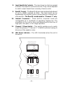
7. Signal Input Switches – These switches allow the input signals to
be distributed to the outputs in many different configurations.
–5–
8.
Input Sensitivity Controls – The input level controls are preset
to match the output of most source units. They can be adjusted
to match output levels from a variety of source units.
9.
Bass EQ Control – The Bass EQ allows a narrow band adjustment
of up to +18dB centered at 45Hz. The bass boost can be
bypassed by turning the control to its minimum or counterclockwise position. The Bass EQ is dedicated for “Channel C” only.
10.
Internal Crossovers – These built-in crossover cards are
configurable for a multitude of operating frequencies. The
orientation of the card in its socket determines the function of
high-pass, low-pass, or full range operation.
11.
Channel C Phase Switch – This switch enables you to easily
invert the phase of “Channel C” (0°/180°) without having to
disconnect the speaker wires.
12.
LED Power Indicator – The LED illuminates when the unit is
turned on.
*Please refer to Owner's
Manual for signal input
switch configurations.
*Signal
Input
Switches
Phase
Switch
–180° 0°
11
7
Ch. B
Dual Filter
XCards
–6–
XCard A
XCard A
XCard B
XCard B
XCard B
Ch. C
XCard
XCard B
XCard C
–180° 0°
XCard C
10
Ch. A
XCards
I N S TA L L AT I O N C O N S I D E R AT I O N S
The following is a list of tools you will need for installing the Punch
amplifier:
Allen wrenches 9/64" & 3/32" (included)
Wire strippers
Electric hand drill w/assorted bits
Wire crimpers
Voltmeter
Battery post wrench
Wire cutters
Assorted connectors
This section focuses on some of the vehicle considerations for
installing your new Punch amplifier. Checking your battery and
present sound system, as well as pre-planning your system layout and
best wiring routes will save installation time. When deciding how to
lay out your new system, be sure that each component will be easily
accessible for making adjustments.
Before beginning any installation, be sure to follow these simple rules:
1. Be sure to carefully read and understand the instructions before
attempting to install the amplifier.
2. For safety, disconnect the negative lead from the battery prior to
beginning the installation.
3. For easier assembly, we suggest you run all wires prior to
mounting your amplifier in place.
4. Route all of the RCA cables close together and away from any high
current wires.
5. Use high quality connectors for a reliable installation and to
minimize signal or power loss.
6. Think before you drill! Be careful not to cut or drill into gas tanks,
fuel lines, brake or hydraulic lines, vacuum lines or electrical
wiring when working on any vehicle.
7. Never run wires underneath the vehicle. Running the wires inside
the vehicle provides the best protection.
8. Avoid running wires over or through sharp edges. Use rubber or
plastic grommets to protect any wires routed through metal,
especially the firewall.
9. ALWAYS protect the battery and electrical system from damage
with proper fusing. Install a fuseholder and appropriate fuse on
the +12V power wire within 18” (45.7 cm) of the battery terminal.
10. When grounding to the chassis of the vehicle, scrape all paint
from the metal to ensure a good, clean ground connection.
Grounding connections should be as short as possible and always
be connected to metal that is welded to the main body, or chassis,
of the vehicle.
–7–
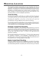
M OUNTING L OCATION
The mounting location and position of your amplifier will have a
great effect on its ability to dissipate the heat generated during normal
operation. The design of our cast aluminum heatsink serves to easily
dissipate the heat generated over a wide range of operating conditions. However, to maximize the performance of your amplifier, care
should be taken to ensure adequate ventilation.
Trunk Mounting
Mounting the amplifier vertically on a surface with the fin grooves
running up and down will provide the best cooling of the amplifier.
Mounting the amplifier on the floor of the trunk will work but
provides less cooling capability than vertical mounting.
Mounting the amplifier upside down to the rear deck of the trunk will
not provide proper cooling and will severely affect the performance
of the amplifier and is strongly not recommended.
Passenger Compartment Mounting
Mounting the amplifier in the passenger compartment will work as
long as you provide a sufficient amount of air for the amplifier to cool
itself. If you are going to mount the amplifier under the seat of the
vehicle, you must have at least 1" (2.54cm) of air gap around the
amplifier's heatsink.
Mounting the amplifier with less than 1" (2.54cm) of air gap around
the amplifier's heatsink in the passenger compartment will not
provide proper cooling and will severely affect the performance of
the amplifier and is strongly not recommended.
Engine Compartment Mounting
Rockford Fosgate amplifiers should never be mounted in the engine
compartment. Not only will this void your warranty but could create
an embarrassing situation caused by the ridicule from your friends.
–8–
B ATTERY
AND
C HARGING
Amplifiers will put an increased load on the vehicle's battery and
charging system. We recommend checking your alternator and
battery condition to ensure that the electrical system has enough
capacity to handle the increased load of your stereo system. Stock
electrical systems which are in good condition should be able to
handle the extra load of any Rockford amplifier without problems,
although battery and alternator life can be reduced slightly. To
maximize the performance of your Rockford Fosgate amplifier, we
suggest the use of a heavy duty battery and an energy storage
capacitor.
WIRING
THE
SYSTEM
CAUTION: Avoid running power wires near the low level input
cables, antenna, power leads, sensitive equipment or harnesses. The
power wires carry substantial current and could induce noise into
the audio system.
• For safety, disconnect the negative lead from the battery prior to
beginning the installation.
1. Configure the internal XCard crossover and Signal Switching
Network prior to installation. Refer to pages 12 & 13 for further
information.
2. Plan the wire routing. Take care when running signal level RCA
cables to keep them close together but isolated from the amplifier's
power cables and any high power auto accessories, especially
electric motors. This is done to prevent coupling the noise from
radiated electrical fields into the audio signal. When feeding the
wires through the firewall or any metal barrier, protect them with
plastic or rubber grommets to prevent short circuits. Leave the
wires long at this point to adjust for a precise fit at a later time.
3. Prepare the Power cable for at- STRIP WIRE
INSULATION
>
>
tachment to the amplifier by stripping 5/8" of insulation from the
<
>
5/8"
end of the wire. To prevent the
AMP
wire from fraying, strip the insula>
tion at a 45° angle. Insert the bared
wire into the B+ terminal with the
long side of the insulation on the
top. Bend the cable down at a 90°
angle. Tighten the set screw to secure the cable in place.
–9–
Mount the fuseholder within 18" of the battery using two (2) #8
screws. Disassemble the fuseholder. You should have 2 black
plastic end caps, 2 gold-plated fuse clips, a plastic spacer and the
fuseholder body. Trim the amplifier power cable to reach the
fuseholder and strip the wire 3/8". Slide one of the end caps over
the wire (narrow end first) and insert the wire into one of the fuse
clips. Tighten the set screw. Screw the black end cap to the
fuseholder body to secure the cable. Use the section of cable that
was trimmed earlier and connect it to the other end of the
fuseholder. Install the plastic spacer in the fuseholder and attach
the cable to the fuseholder body.
NOTE: The B+ cable MUST be fused 18" or less from the vehicle's
battery. Install the fuseholder under the hood and prepare the
cable ends as stated above. Connections should be water tight.
4. Strip 3/8" from the battery end of the power cable and crimp a large
ring terminal to the cable. Use the ring terminal to connect to the
battery positive terminal. Do not install the fuse at this time.
5. Prepare a length of cable to be used for the GND connection. Strip
5/8" of insulation from the end of the cable as described previously
and connect to the appropriate terminal of the amplifier. Prepare
the chassis ground by scraping any paint from the metal surface
and thoroughly clean the area of all dirt and grease. Strip the other
end of the wire and attach a ring connector. Fasten the cable to the
chassis using a non-anodized screw and a star washer.
6. Prepare the REM turn-on wire for connection to the amplifier by
stripping 1/4" of insulation from the wire end and crimping an
insulated spade connector in place. Slide the connector over the
REM terminal on the amplifier. Connect the other end of the REM
wire to a switched 12 volt positive source. The switched signal is
usually taken from the source unit's auto antenna or the accessory
lead. If the source unit does not have these outputs available, the
recommended solution is to wire a mechanical switch in line with
a 12 volt source to activate the amplifier.
7. Securely mount the amplifier (with supplied screws) to the
vehicle or amp rack. Be careful not to mount the amplifier on
cardboard or plastic panels. Doing so may enable the screws to
pull out from the panel due to road vibration or sudden vehicle
stops.
– 10 –
8. Connect the source signal to the amplifier by plugging the RCA
cables into the input jacks at the amplifier.
9. Connect the speakers. Strip the speaker wires 5/8". Insert the bared
wire into the speaker terminal and tighten the set screw to secure
into place. Be sure to maintain proper speaker polarity. DO NOT
chassis ground any of the speaker leads as unstable operation
may result.
10. Perform a final check of the completed system wiring to ensure
that all connections are accurate. Check all power and ground
connections for frayed wires and loose connections which could
cause problems.
11. After the final inspection is complete, install the power fuse and
enjoy listening. During the initial listening period, you may need
to “fine tune” any phasing and level settings within your particular
vehicle. To aid in this procedure, play a track with high musical
content and cruise around your neighborhood. After fully evaluating the transient response of your system and making any final
adjustments, all your neighbors within a 1 mile radius will assume
that you have just successfully completed another upgrade to your
audio system for which they will probably spill thumbtacks on
your driveway.
– 11 –
USING
THE
XCARD
The crossover functions are controlled through the use of an XCard
and can be set for high-pass, low-pass or full range operation. The
XCard installed in your amplifier is set for Full Range. Each crossover
card has two faces: one face operates Full Range, the other has arrows
to indicate the edge for selecting HP (high-pass) or LP (low-pass)
operation. Orient the card with the desired operating edge, indicated
by the arrow, toward the socket terminals inside the amplifier. Firmly,
but carefully, plug the card into the socket.
LP
CUSTOMIZING
➝
HP
THE
Full Range
➝
➝
➝
Low-Pass
HP
High-Pass
FULL ↕
LP
XC ARD
The crossover point can be altered by changing all 4 resistor values.
Use the following formula to select the appropriate resistor value to
be placed on the XCard.
3386
fo
= R (in kΩ) for .047µf cap
7234
fo
= R (in kΩ) for .022µf cap
a
d
v
a
n
c
e
d
The actual formula is:
1
2πfoc
Where: R = Ω
fo = desired crossover frequency
c = capacitor in farads
ex: .047 x 10-6 for .047mf cap
– 12 –
FULL
R2
High Pass
Low Pass
Full Range
R1
R2
Crossover Card
R1
R=
O
p
e
r
a
t
i
o
n
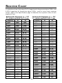
R ESISTOR C HART
Our tests have shown that using 0.047µf capacitors for frequencies below 100Hz, and
0.022µf capacitors for frequencies above 100Hz, result in more linear crossover
control. Refer to the Specifications page to determine the capacitor value of each
supplied XCard.
Butterworth Alignment Q = .707
Butterworth Alignment Q = .707
1% resistors used with 0.047µF caps
1% resistors used with 0.022µF caps
Frequency
20Hz
25Hz
30Hz
35Hz
40Hz
45Hz
50Hz
55Hz
60Hz
65Hz
70Hz
75Hz
80Hz
85Hz
90Hz
200Hz
300Hz
400Hz
500Hz
600Hz
700Hz
800Hz
900Hz
1kHz
1.2kHz
2kHz
3kHz
4kHz
5kHz
6kHz
7kHz
8kHz
R1
169kΩ
133kΩ
110kΩ
95.3kΩ
84.5kΩ
75kΩ
68.1kΩ
61.9kΩ
56.2kΩ
52.3kΩ
48.7kΩ
45.3kΩ
42.2kΩ
40.2kΩ
37.4kΩ
16.9kΩ
11.3kΩ
8.45kΩ
6.65kΩ
5.62kΩ
4.75kΩ
4.22kΩ
3.74kΩ
3.40kΩ
2.80kΩ
1.69kΩ
1.10kΩ
845Ω
665Ω
562Ω
487Ω
422Ω
R2
169kΩ
133kΩ
110kΩ
95.3kΩ
84.5kΩ
75kΩ
68.1kΩ
61.9kΩ
56.2kΩ
52.3kΩ
48.7kΩ
45.3kΩ
42.2kΩ
40.2kΩ
37.4kΩ
16.9kΩ
11.3kΩ
8.45kΩ
6.65kΩ
5.62kΩ
4.75kΩ
4.22kΩ
3.74kΩ
3.40kΩ
2.80kΩ
1.69kΩ
1.10kΩ
845Ω
665Ω
562Ω
487Ω
422Ω
Frequency
20Hz
25Hz
30Hz
35Hz
40Hz
45Hz
50Hz
55Hz
60Hz
65Hz
70Hz
75Hz
80Hz
85Hz
90Hz
200Hz
300Hz
400Hz
500Hz
600Hz
700Hz
800Hz
900Hz
1.0kHz
1.2kHz
2.0kHz
3.0kHz
4.0kHz
5.0kHz
6.0kHz
7.0kHz
8.0kHz
– 13 –
R1
357kΩ
287kΩ
237kΩ
205kΩ
178kΩ
162kΩ
143kΩ
130kΩ
121kΩ
110kΩ
102kΩ
95.3kΩ
90.9kΩ
84.5kΩ
80.6kΩ
35.7kΩ
23.7kΩ
17.8kΩ
14.3kΩ
12.1kΩ
10.2kΩ
9.9kΩ
8.6kΩ
7.15kΩ
6.04kΩ
3.57kΩ
2.37kΩ
1.76kΩ
1.43kΩ
1.21kΩ
1.02kΩ
909Ω
R2
357kΩ
287kΩ
237kΩ
205kΩ
178kΩ
162kΩ
143kΩ
130kΩ
121kΩ
110kΩ
102kΩ
95.3kΩ
90.9kΩ
84.5kΩ
80.6kΩ
35.7kΩ
23.7kΩ
17.8kΩ
14.3kΩ
12.1kΩ
10.2kΩ
9.9kΩ
8.6kΩ
7.15kΩ
6.04kΩ
3.57kΩ
2.37kΩ
1.76kΩ
1.43kΩ
1.21kΩ
1.02kΩ
909Ω
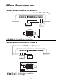
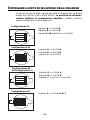
XCARD CONFIGURATIONS
Configure a 12dB/octave filter for Channel A
–
L
+
–
Ch. B
R
+
REM
Dual B+
Dual GND
+
L
–
+
Ch. A
Ch. B
80Hz-20kHz
12dB/octave HP
XCard B
–
80Hz-20kHz
12dB/octave HP
0° 180°
XCard C
R
Ch. A
XCard B
XCard A
XCard A
HP
• XCard A set to High-Pass or Low-Pass
Configure a 12dB/octave filter for Channel B
L
Ch. B
+
–
R
+
REM
Dual B+
Dual GND
20Hz-80Hz
12dB/octave LP
XCard B2
Full
Range
20Hz-80Hz
12dB/octave LP
XCard C
XCard B
XCard B
XCard B1
LP
+
L
Ch. A
Ch. B
0° 180°
–
XCard A
• XCard B1 set to High-Pass or Low-Pass
• XCard B2 set to Full Range
– 14 –
–
+
R
Ch. A
–
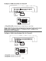
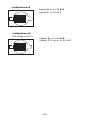
Configure a 24dB/octave filter for Channel B
L
+
–
Ch. B
R
REM
+
Dual B+
Dual GND
+
L
–
+
Ch. A
Ch. B
R
–
Ch. A
20Hz-80Hz
24dB/octave LP
20Hz-80Hz
24dB/octave LP
XCard B2
LP
XCard C
XCard B
*
0° 180°
–
XCard B
XCard A
XCard B1
LP
• XCard B1 & B2 set identically to High-Pass or Low-Pass
*Note: Both XCards must be customized to the same frequency for proper
24dB/octave operation. Refer to “Using the XCard” on page 12 for
altering the cutoff frequency.
Configure a 12dB/octave Bandpass filter for Channel B
L
Ch. B
+
–
R
+
REM
Dual B+
Dual GND
80Hz-4kHz
12dB/octave BP
80Hz-4kHz
12dB/octave BP
XCard B2
LP
XCard C
XCard B
XCard B
XCard B1
HP
+
L
Ch. A
Ch. B
XCard A
• XCard B1 inserted as High-Pass
• XCard B2 inserted as Low-Pass
– 15 –
0° 180°
–
–
+
R
Ch. A
–
Configure a 12dB/octave Low-Pass filter for Channel C
R
R
R
LED
+
L
–
Ch. C Ch. C
Bass EQ Gain L
Ch. C
Ch. B
Gain
L
L
Ch. C
Ch. B
+
Ch. A
Gain
R –
Ch. C
Ch. A
XCard C
LP
XCard C
XCard B
0° 180°
20Hz-80Hz
12dB/octave LP
XCard B
XCard A
• XCard C set to High-Pass or Low-Pass
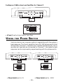
U SING
THE
PHASE SWITCH
Vehicle interiors can cause acoustical irregularities with the system's
bass response. The Punch amplifier has a 0°/–180° phase switch that
allows both Channel C outputs to be inverted simultaneously. Since
woofers will typically be connected to Channel C, the system's bass
response can be improved by experimenting with the phase switch.
R
R
R
Ch. C Ch. C
Bass EQ Gain L
L
L
–
Ch. C
Ch. B
Ch. B
Gain
Ch. A
Gain
+
+
R –
Ch. C
R
R
L
R
Ch. B
Gain
L
Ch. B
Ch. A
Gain
+
R –
Ch. C
Ch. A
180° Phase
XCard C
0° –180°
XCard B
–
Ch. C
Ch. A
0° Phase
XCard C
L
Ch. C
XCard B
0° –180°
L
Ch. C
Ch. C Ch. C
Bass EQ Gain L
LED
LED
+
XCard B
XCard B
XCard A
XCard A
• Phase Switch set to 0°
• Phase Switch set to –180°
– 16 –
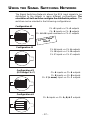
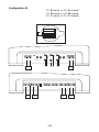
USING THE SIGNAL SWITCHING NETWORK
The Signal Switching Network allows the RCA input signals to be
distributed to the outputs in many different configurations. The
orientation of both switches configure the distribution pattern. The
switches can be oriented in the following configurations:
Configuration #1
XCard
C
XCard
B
XCard
B
XCard
A
–180°
0°
Ch. A inputs => Ch. A outputs
Ch. B inputs => Ch. B outputs
Ch. A & B inputs summed => Ch. C outputs
ult
y Defa
Factor ing
Sett
Configuration #2
XCard
C
XCard
B
XCard
B
XCard
A
–180°
0°
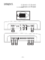
Configuration #3
(E-Z bridge Ch. C)
XCard
C
XCard
B
XCard
B
XCard
A
Ch. A inputs => Ch. A outputs
Ch. B inputs => Ch. B outputs
Ch. C inputs => Ch. C outputs
Ch. A inputs => Ch. A outputs
Ch. B inputs => Ch. B outputs
Ch. C (L mono) input => Ch. C outputs
–180°
0°
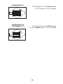
Configuration #4
Ch. A inputs => Ch. A, B, & C outputs
XCard
C
XCard
B
XCard
B
XCard
A
–180°
0°
– 17 –
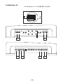
Configuration #5
Ch. A inputs => Ch. A & B outputs
Ch. C inputs => Ch. C outputs
XCard
C
XCard
B
XCard
B
XCard
A
–180°
0°
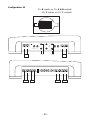
Configuration #6
(E-Z bridge Ch. C)
XCard
C
XCard
B
XCard
B
XCard
A
Ch. A inputs => Ch. A & B outputs
Ch. C ( L mono) input => Ch. C outputs
–180°
0°
– 18 –
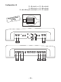
Configuration #1
Ch. A inputs => Ch. A outputs
Ch. B inputs => Ch. B outputs
Ch. A & B inputs summed => Ch. C outputs
ult
y Defa
Factor ing
Sett
XCard
C
XCard
B
XCard
B
XCard
A
R
–180°
0°
R
R
LED
+
L
–
Ch. C Ch. C
Bass EQ Gain L
Ch. C
–
L
+
Ch. B
–
R
+
REM
Dual B+
Ch. A
Gain
+
R –
Ch. C
Ch. A
B B
A&B
Ch. B
Gain
L
L
Ch. C
A A
Dual GND
A&B
+
L
–
+
R
Ch. B
Ch. B
Ch. A
Ch. A
B
B
A
A
– 19 –
–
Configuration #2
Ch. A inputs => Ch. A outputs
Ch. B inputs => Ch. B outputs
Ch. C inputs => Ch. C outputs
XCard
C
XCard
B
XCard
B
XCard
A
–180°
0°
R
R
R
Ch. C Ch. C
Bass EQ Gain L
L
L
LED
+
L
–
Ch. C
Ch. C
C C
C
–
L
Ch. B
+
–
R
+
REM
Dual B+
Ch. B
Gain
Ch. A
Gain
+
R –
Ch. C
Ch. A
B B
A A
Dual GND
C
+
L
–
+
R
Ch. B
Ch. B
Ch. A
Ch. A
B
B
A
A
– 20 –
–
Configuration #3
(E-Z bridge Ch. C)
Ch. A inputs => Ch. A outputs
Ch. B inputs => Ch. B outputs
Ch. C (L mono) input => Ch. C outputs
XCard
C
XCard
B
XCard
B
XCard
A
–180°
0°
R
R
R
Ch. C Ch. C
Bass EQ Gain L
L
L
LED
+
L
–
Ch. C
Ch. C
C
(Mono)
C
–
L
Ch. B
+
–
R
+
REM
Dual B+
Ch. B
Gain
Ch. A
Gain
+
R –
Ch. C
Ch. A
B B
A A
Dual GND
C
+
L
–
+
R
Ch. B
Ch. B
Ch. A
Ch. A
B
B
A
A
– 21 –
–
Configuration #4
Ch. A inputs => Ch. A, B, & C outputs
XCard
C
XCard
B
XCard
B
XCard
A
R
–180°
0°
R
R
LED
+
L
–
Ch. C Ch. C
Bass EQ Gain L
Ch. C
Ch. B
L
Ch. A
Gain
+
A A
+
–
R
+
REM
Dual B+
R –
Ch. C
Ch. A
A
–
Ch. B
Gain
L
L
Ch. C
Dual GND
A
+
L
–
+
R
Ch. B
Ch. B
Ch. A
Ch. A
A
A
A
A
– 22 –
–
Configuration #5
Ch. A inputs => Ch. A & B outputs
Ch. C inputs => Ch. C outputs
XCard
C
XCard
B
XCard
B
XCard
A
R
–180°
0°
R
R
LED
+
L
–
Ch. C Ch. C
Bass EQ Gain L
Ch. C
–
L
Ch. B
+
–
R
+
REM
Dual B+
Ch. A
Gain
+
R –
Ch. C
Ch. A
A A
C C
C
Ch. B
Gain
L
L
Ch. C
Dual GND
C
+
L
–
+
R
Ch. B
Ch. B
Ch. A
Ch. A
A
A
A
A
– 23 –
–
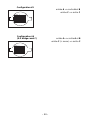
Configuration #6
(E-Z bridge Ch. C)
Ch. A inputs => Ch. A & B outputs
Ch. C ( L mono) input => Ch. C outputs
XCard
C
XCard
B
XCard
B
XCard
A
R
R
–180°
0°
R
LED
+
L
–
Ch. C Ch. C
Bass EQ Gain L
Ch. C
–
L
Ch. B
+
–
R
+
REM
Dual B+
Ch. A
Gain
+
R –
Ch. C
Ch. A
C
(Mono)
C
Ch. B
Gain
L
L
Ch. C
A A
Dual GND
C
+
L
–
+
R
Ch. B
Ch. B
Ch. A
Ch. A
A
A
A
A
– 24 –
–
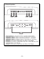
360.6 I NSTALLATION
®
®
Power Connections (Option #1)
–
L
+
–
Ch. B
R
+
REM
Dual B+
Dual GND
+
L
–
+
Ch. A
Ch. B
Connect to remote
turn-on lead of
source unit
R
–
Ch. A
Connect to chassis
ground of vehicle*
less than 18"
–
+
Battery
*Keep grounds as
short as possible
Connect to B+ of battery
with 50 amp fuse
Power Connections (Option #2)
–
R
+
REM
Dual
B+
Dual GND
+
L
Ch. A
Ch. B
+
R
–
Ch. A
Connect to chassis
ground of vehicle*
®
®
the connecting
®
Connect to remote
turn-on lead of
source unit
less than 18"
+
*Keep grounds as
short as possible
–
–
Battery
Connect to B+ of battery
with 50 amp fuse
– 25 –
1 farad • 20 VDC • 95°C
+
cap
L
Ch. B
1.0punch
–
Optional Energy
Storage Capacitor
I
N
S
T
A
L
L
A
T
I
O
N
®
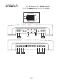
3-Channel Operation
–
L
+
–
Ch. B
R
+
REM
Dual B+
Dual GND
Ch. B
+
L
Left
–
–
+
Ch. A
Right
+
–
–
+
4 ohm min.
R
Ch. A
4 ohm min.
R
R
R
LED
+
L
Ch. C
–
Ch. C Ch. C
Bass EQ Gain L
Ch. B
Gain
L
L
Ch. C
Ch. B
Ch. A
Gain
+
R –
Ch. C
Ch. A
–
+
4 ohm min.
• Gain Control for channels A & B set equally to balance the left and
right speakers
• Gain Control for channel C operates independently
• Impedance Load for bridged left channel should be 4Ω minimum
• Impedance Load for bridged right channel should be 4Ω minimum
• Impedance Load for bridged C channel should be 4Ω minimum
• XCards A & B set identically as 12dB High-Pass, 12dB Low-Pass or
Full Range
• XCard C can be set for High-Pass, Low-Pass or Full Range
– 26 –
®
I
N
S
T
A
L
L
A
T
I
O
N
®
3-Channel Mono Operation
–
L
+
–
Ch. B
R
+
REM
Dual B+
Dual GND
Ch. B
–
+
L
–
Ch. A
+
+
R
–
+
4 ohm min.
–
Ch. A
4 ohm min.
R
R
R
LED
+
L
Ch. C
–
Ch. C Ch. C
Bass EQ Gain L
Ch. B
Gain
L
L
Ch. C
Ch. B
Ch. A
Gain
+
R –
Ch. C
Ch. A
–
+
4 ohm min.
• Gain Control for channels A, B & C operate independently
• Impedance Load for bridged channel A should be 4Ω minimum
• Impedance Load for bridged channel B should be 4Ω minimum
• Impedance Load for bridged channel C should be 4Ω minimum
• XCard A can be set for High-Pass, Low-Pass or Full Range
• XCard B can be set for 12dB High-Pass, 12dB Low-Pass or Full
Range
• XCard C can be set for High-Pass, Low-Pass or Full Range
– 27 –
®
I
N
S
T
A
L
L
A
T
I
O
N
®
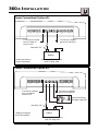
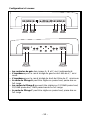
4-Channel Stereo Operation
–
L
+
–
Ch. B
R
+
REM
Dual B+
Dual GND
Ch. B
+
L
–
+
Left
+
+
4 ohm min.
–
Ch. A
Right
–
R
Ch. A
–
4 ohm min.
R
R
R
LED
+
L
–
Ch. C Ch. C
Bass EQ Gain L
Ch. C
Ch. B
–
+
Ch. B
Gain
L
L
Ch. C
+
Ch. A
Gain
R –
Ch. C
Ch. A
–
+
2 ohm min.
2 ohm min.
• Gain Control for channels A & B set equally
• Gain Control for channel C operates independently
• Impedance Load for bridged left channel should be 4Ω minimum
• Impedance Load for bridged right channel should be 4Ω minimum
• Impedance Load for stereo channel C should be 2Ω minimum
• XCards A & B set identically as 12dB High-Pass, 12dB Low-Pass or
Full Range
• XCard C can be set for High-Pass, Low-Pass or Full Range
– 28 –
®
I
N
S
T
A
L
L
A
T
I
O
N
5-Channel Operation
–
L
+
–
Ch. B
–
–
Rear
+
R
+
REM
Dual B+
Dual GND
+
Ch. B
–
+
–
+
2 ohm min.
2 ohm min.
L
+
Ch. A
Front
–
2 ohm min.
R
R
R
–
Ch. A
+
–
2 ohm min.
R
LED
+
L
Ch. C
–
Ch. C Ch. C
Bass EQ Gain L
Ch. B
Gain
L
L
Ch. C
Ch. B
Ch. A
Gain
+
R –
Ch. C
Ch. A
–
+
4 ohm min.
• Gain Controls for channels A, B & C operate independently
• Impedance Load for stereo channel A should be 2Ω minimum
• Impedance Load for stereo channel B should be 2Ω minimum
• Impedance Load for bridged channel C should be 4Ω minimum
• XCard A can be set for High-Pass, Low-Pass or Full Range
• XCard B can be set for 12dB/24dB High-Pass, 12dB/24dB Low-Pass
12dB Bandpass or Full Range
• XCard C can be set for High-Pass, Low-Pass or Full Range
– 29 –
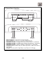
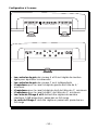
6-Channel Stereo Operation
–
L
+
–
Ch. B
–
–
Rear
+
R
+
–
2 ohm min.
REM
Dual B+
Dual GND
+
Ch. B
L
–
+
Ch. A
+
+
2 ohm min.
Front
–
R
–
+
2 ohm min.
R
R
Ch. A
–
2 ohm min.
R
LED
+
L
–
Ch. C Ch. C
Bass EQ Gain L
Ch. C
+
Ch. B
Gain
L
L
Ch. C
Ch. B
+
Ch. A
Gain
R –
Ch. C
Ch. A
+
–
2 ohm min.
–
2 ohm min.
• Gain Control for channels A, B & C operate independently
• Impedance Load for stereo channels A, B & C should be 2Ω minimum
• XCard A can be set for High-Pass, Low-Pass or Full Range
• XCard B can be set for 12dB/24dB High-Pass, 12dB/24dB Low-Pass
12dB Bandpass or Full Range
• XCard C can be set for High-Pass, Low-Pass or Full Range
– 30 –
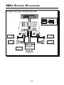
360.6 S Y S T E M D I A G R A M S
Bridged Left & Right w/Bridged Subwoofer
R
AUD
VOL
PWR
CLOCK
DISC
AMFM
ST
Ch
LD RDM RPT
®
AUTO
DSPL
SEL
ILLUM
P.SCN
LOUD
D.SCN
SCAN
RPT
RDM
DIM
PAUSE
1
2
3
4
5
6
TUNE
®
80Hz LP
FULL
80Hz HP
XCard
C
XCard
B
XCard
B
XCard
A
–180°
0°
80Hz HP
360.6
RFA-514
RFA-514
®
®
ACTIVE TWEETER PROTECTION
PCH-142x
ACTIVE TWEETER PROTECTION
PCH-142x
®
®
6kHz-20Hz
18dB/octave High-Pass
+
+
–
–
–
6kHz-20Hz
18dB/octave High-Pass
+
+
80Hz-6kHz
12dB/octave Bandpass
®
®
+
–
8 Ohm
+
–
20Hz-80Hz
12dB/octave Low-Pass
8 Ohm
RFP-1812
– 31 –
–
80Hz-6kHz
12dB/octave Bandpass
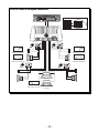
Front & Rear w/Bridged Subwoofer
R
AUD
VOL
PWR
CLOCK
DISC
AMFM
ST
Ch
LD RDM RPT
®
AUTO
DSPL
SEL
ILLUM
P.SCN
LOUD
D.SCN
SCAN
RPT
RDM
DIM
PAUSE
1
2
3
4
5
6
TUNE
®
80Hz LP
FULL
80Hz HP
XCard
C
XCard
B
XCard
B
XCard
A
–180°
0°
80Hz HP
360.6
RFA-514
RFA-514
®
®
ACTIVE TWEETER PROTECTION
PCH-142x
ACTIVE TWEETER PROTECTION
PCH-142x
®
®
6kHz-20Hz
18dB/octave High-Pass
+
+
–
–
80Hz-6kHz
12dB/octave Bandpass
®
®
®
+
+
–
–
6kHz-20Hz
18dB/octave High-Pass
80Hz-6kHz
12dB/octave Bandpass
®
®
ACTIVE TWEETER PROTECTION
PCH-142x
®
ACTIVE TWEETER PROTECTION
PCH-142x
®
®
+
+
+
–
–
–
+
+
8 Ohm
+
–
20Hz-80Hz
12dB/octave Low-Pass
–
8 Ohm
RFP-1812
– 32 –
–
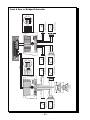
– 33 –
80Hz-4.5kHz
12dB/octave Bandpass
4.5kHz-20Hz
12dB/octave High-Pass
–
+
–
+
RFA-54
RFA-14
+
+
8 Ohm
RFP-1812
8 Ohm
–
–
RFA-54
–
+
RFA-14
360.6
–
+
B
A
XCard
XCard
–180°
0°
PWR
AUD
80Hz-4.5kHz
12dB/octave Bandpass
4.5kHz-20Hz
12dB/octave High-Pass
B
C
XCard
XCard
80Hz-4.5kHz
12dB/octave Bandpass
4.5kHz-20Hz
12dB/octave High-Pass
4.5kHz HP
80Hz HP
4.5kHz LP
80Hz LP
Front
VOL
®
DISC
AMFM
–
+
ST
–
+
®
SCAN
2
1
DSPL
CLOCK
D.SCN
RFA-54
RFA-14
Ch
LD RDM RPT
AUTO
3
RPT
P.SCN
4
RDM
ILLUM
LOUD
5
DIM
6
PAUSE
SEL
360.6
R
RFA-54
–
+
RFA-14
TUNE
–
+
Not Used
XCard
XCard
XCard
XCard
80Hz-6kHz
12dB/octave Bandpass
4.5kHz-20Hz
12dB/octave High-Pass
4.5kHz HP
80Hz HP
4.5kHz LP
A
B
B
C
–180°
0°
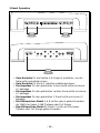
Front & Rear w/Bridged Subwoofer
– 34 –
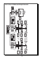
80Hz-400Hz
12dB/octave High-Pass
6dB/octave Low-Pass
400Hz-4.5kHz
12dB/octave Bandpass
4.5kHz-20Hz
12dB/octave High-Pass
–
+
–
–
+
+
+
RFA-64
RFA-54
–
RFA-64
RFA-54
RFA-14
–
+
RFA-14
360.6
–
+
B
A
XCard
80Hz-400Hz
12dB/octave High-Pass
6dB/octave Low-Pass
–180°
0°
80Hz-400Hz
12dB/octave High-Pass
6dB/octave Low-Pass
400Hz-4.5kHz
12dB/octave Bandpass
PWR
AUD
4.5kHz-20Hz
12dB/octave High-Pass
B
XCard
C
XCard
XCard
400Hz-4.5kHz
12dB/octave Bandpass
4.5kHz-20Hz
12dB/octave High-Pass
4.5kHz HP
400Hz HP
4.5kHz LP
80Hz LP
Front
VOL
®
–
+
DISC
AMFM
–
+
–
+
ST
SCAN
2
1
DSPL
CLOCK
D.SCN
RFA-64
RFA-54
RFA-14
®
Ch
LD RDM RPT
AUTO
3
RPT
P.SCN
4
RDM
ILLUM
LOUD
5
6
PAUSE
R
–
+
–
+
RFA-14
360.6
TUNE
RFA-54
SEL
RFA-64
DIM
–
+
80Hz LP
80Hz-400Hz
12dB/octave High-Pass
6dB/octave Low-Pass
400Hz-4.5kHz
12dB/octave Bandpass
A
B
B
C
–180°
0°
20Hz-80Hz
12dB/octave Low-Pass
XCard
XCard
XCard
XCard
4.5kHz-20Hz
12dB/octave High-Pass
4.5kHz HP
400Hz HP
4.5 kHz LP
+
+
8 Ohm
RFP-1812
8 Ohm
–
–
XCard
80Hz LP
Front & Rear w/Midbass and Bridged Subwoofer
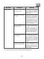
TROUBLESHOOTING
Symptom
Amplifier does not
turn on
(Power LED is off)
Amplifier has no
sound
(Power LED is on)
Diagnosis
TROUBLE-S
H
O
O
T
I
N
G
Remedy
Voltage applied to the
REM terminal of the
amplifier is not between
10.5 and 15.5 volts or
there is no voltage
present.
Check the alternator, battery, fuse, and wiring and
repair as necessary. If the
voltage is above 15.5 volts,
have the electrical system
inspected by an authorized
car service center.
Voltage to the B+ terminal of the amplifier is
not between 10.5 and
15.5 volts or there is no
voltage present.
Check the alternator, battery, fuse, and wiring and
repair as necessary. If the
voltage is above 15.5 volts,
have the electrical system
inspected by an authorized
car service center.
Amplifier is not properly grounded.
Check wiring and repair as
necessary.
RCA Input from source
unit is not connected or
not functioning properly.
Check connections, substitute with known working
source and cables and repair
or replace as necessary.
XCard is missing or not
placed properly in crossover slots.
Check XCard position and
repair or replace as necessary.
Speaker leads are
shorted to each other or
to the chassis of the vehicle.
Disconnect existing speakers and test with known
working speakers and wires.
If amplifier plays, check and
repair wiring and installation of speakers as necessary.
Speakers are defective.
Disconnect existing speakers and test with known
working speakers. If amplifier plays, check and repair
speakers as necessary.
– 35 –
Symptom
Diagnosis
Remedy
TROUBLE-S
H
O
O
T
I
N
G
Input gain signal for amplifier is incorrectly set.
Readjust input gains of
amplifier.
Source unit output too
low or source unit has
no output.
Check system with known
working source and repair
or replace original source
as needed.
XCard is missing or not
placed properly in crossover slots.
Check XCard position and
repair or replace as necessary.
Low battery voltage or
large voltage drops to
the amplifier under load.
Check the alternator, battery, fuse, and power and
ground wiring. Repair as
necessary.
Signal Input Switches not
configured properly.
Check Signal Input
Switches and reconfigure
as necessary.
XCard(s) missing or not
placed properly in crossover slot.
Check XCard position(s)
and repair or replace as
necessary.
Low Output on
Channel C
(L mono RCA input)
Signal Input Switches do
not configure Channel C
for E-Z Bridge.
Check Signal Input
Switches and reconfigure
as necessary.
Amplifier Noise
(Turn-on pop)
Voltage spike from output of preceding component is entering amplifier
through input signal.
Disconnect input signal to
amplifier and turn amplifier on and off. If noise is
eliminated, connect REM
lead of amplifier to source
unit with a delay turn-on
module.
Voltage spike from remote
turn-on lead is entering
through REM input terminal.
Use a different 12 volt
source for REM lead of
amplifier. (i.e., battery direct) If noise is eliminated,
use a relay to isolate amplifier from noisy turn-on
output.
Speaker Output
Low or Distorted
No Output on
Channel A, Channel B, or Channel C
– 36 –
TROUBLE-S
H
O
O
T
I
N
G
Symptom
Engine Noise
Diagnosis
Remedy
Noise is radiating into
RCA signal cable.
Check connections, run the
RCA cables on a different
route away from sources of
high current.
Bad component in the signal chain.
Check connections, bypass
additional components
(crossovers and equalizers)
between the source unit
and the amplifier. Connect
one component at a time
to determine the culprit.
Repair or replace components as necessary.
Noise is radiating into
speaker cables.
Disconnect existing speakers and connect a test
speaker to the output terminals of the amplifier. If
noise is gone, reroute the
speaker cables away from
sources of high voltage.
Multiple grounds in the
audio system.
Check ground connections
and connect amplifiers, signal processors, and other
components to a central
location or try a different
grounding point on the
chassis.
Ground loop between
source unit and antenna.
Check connections, disconnect antenna from
source unit. If noise is gone,
install an antenna ground
loop isolator.
• If noise persists, see your Authorized Rockford Fosgate Dealer.
– 37 –
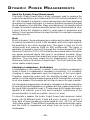
DYNAMIC POWER MEASUREMENTS
About the Dynamic Power Measurements
The Audio Graph PowerCube is a test instrument used to measure the
output of an amplifier in accordance with IHF-202 industry standards. The
IHF-202 standard is a dynamic power measurement and was developed
as a means of measuring power in a manner that best represents the Real
World operation of an amplifier. Many manufacturers, including Rockford
Fosgate, at times will measure amplifier power into a fixed resistor (4 ohm,
2 ohm). While this method is useful in some types of evaluation and
testing, it is not representative of an amplifier that is connected to a speaker
and playing music.
Music
Music is dynamic; the sound waves are complex and constantly changing.
In order to simulate this, the IHF-202 standard calls for the input signal to
the amplifier to be a 1kHz bursted tone. This signal is input (on for 20
milliseconds) and reduced 20dB for 480 milliseconds. The signal is
gradually increased in level until the amplifier's output exceeds 1% Total
Harmonic Distortion (THD). At 1% distortion becomes audible, therefore,
any power produced above that level is considered unusable. Many
manufacturers represent their amplifiers' output power in excess of 10%
distortion. They use many names for this measurement, such as Total
Maximum Power or Maximum Output Power. This is not indicative of the
actual usable output power.
Listening to Loudspeakers - Not Resistors
A loudspeaker is not a resistor. A resistor's value (resistance measured in
ohms) is fixed. A loudspeaker's impedance is dynamic. It is constantly
changing in value, dependent upon the frequency of the input signal.
Therefore, measuring power with the amplifier loaded into a 4 ohm
resistor is not the same as measuring power with the amplifier connected
to a 4 ohm speaker. Most people do not listen to music through a resistor.
A 4 ohm speaker may experience a drop in impedance 4-6 times lower than
its nominal (printed) impedance. A speaker will also create phase shifts in
the signal that is passed through it. These phase shifts happen because a
speaker is an inductor (voice coil) and a capacitor (compliance of the
surround/spider), as well as a resistor (voice coil wire).
To simulate a speaker the Audio Graph PowerCube measures output
power into 20 different loads. It tests at 8 ohms, 4 ohms, 2 ohms and 1
ohm. Each of these impedances is also tested at –60°, –30°, 0°, +30° and
+60° phase angles. These different impedances and phase angles represent the shifts in impedance and phase that can occur in a typical
loudspeaker.
– 38 –
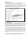
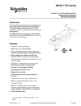
Information Cubed
The data acquired in the testing procedure is then graphed in the form
of a 3-dimensional cube, hence the name PowerCube.
The Phase Angle is expressed on the horizontal axis, the Output
Voltage is presented on the vertical axis and the Impedance is
displayed on the Z axis. Output Power, in watts, is listed on the left
hand side for each impedance at each phase angle.
Audio Graph – The PowerCube™
x2 = STEREO
MONO = BRIDGED MONO
I M P E D A N C E
Amplifier: PUNCH 200.2 14.4V x 2
Serial No:
Owner : ROCKFORD CORPORATION
W
W
W
W
W
W
W
W
W
W
W
W
W
W
W
W
W
W
W
W
{
50V
POWER
IN
WATTS
30V
10V
8Ω
4Ω
–60° (Cap)
2Ω
0°
1Ω
(Ind) +60°
PHASE ANGLES
{
85
84
84
84
86
162
157
156
157
162
273
258
251
256
271
390
356
346
352
390
{
8Ω*–60°
–30°
0°
30°
60°
4Ω*–60°
–30°
0°
30°
60°
2Ω*–60°
–30°
0°
30°
60°
1Ω*–60°
–30°
0°
30°
60°
Rated Power : 100 W @ 4 Ohms
V O L T A G E
VOLTAGE FROM
BATTERY
O U T P U T
MODEL BEING
TESTED
e
danc
Impe
• Example of a Punch 200.2 PowerCube
What is an Amplifier?
An amplifier by definition is a voltage generating device, recreating
the signal which is input to it identically but with increased volume.
It will be connected to a reactive load (the speaker). The impedance
of this load and phase of the signal passing through the load will vary,
dependent upon the frequency of the input signal (music).
Therefore, a perfect amplifier will be able to maintain the same output
voltage regardless of load characteristics and will not alter the signal
it is reproducing. A perfect amplifier when measured by the Audio
Graph PowerCube would present data that forms a perfect cube.
Unfortunately, amplifiers are not perfect. The laws of physics generally prevent it. A great amplifier is about the best one can hope to
attain.
As you can see by the PowerCube and as you will experience by
listening, your Punch amplifier is a GREAT AMPLIFIER!
– 39 –
S P E C I F I C AT I O N S
Continuous Power Rating (Competition Standard) - Measured at 13.8 Battery Volts
RMS continuous power per channel,
all channels driven into a 4Ω load
from 20 to 20,000 Hz with less than
0.05% Total Harmonic Distortion (THD)
30 Watts x 6
RMS continuous power per channel,
all channels driven into a 2Ω load
from 20 to 20,000 Hz, with less than
0.1% Total Harmonic Distortion (THD)
60 Watts x 6
RMS continuous power bridged into a
4Ω load from 20 to 20,000 Hz, with
less than 0.1% Total Harmonic Distortion (THD)
120 Watts x 3
Dynamic Power Rating (IHF-202 Standard) - Measured at 14.4 Volts
Per channel into a 4Ω Load
60 Watts x 6
Per channel into a 2Ω Load
95 Watts x 6
Bridged into a 4Ω Load
190 Watts x 3
Signal-to-Noise Ratio
> 100dB A-weighted
Frequency Response
20Hz-20kHz ±0.5dB
Bandwidth
10Hz-250kHz ±3dB
Damping Factor @ 4Ω
>200 (at output connector)
Slew Rate
30 V/µs
IM Distortion (IHF)
<0.05%
Input Impedance
20k Ohms
Input Sensitivity
Variable from 300mV to 5V
Preset at the factory for 500mV
B+ Fuse Size (External to Amplifier)
50 amp or two 25 amp
Fuse Type
AGU
Crossover Alignment
12dB/octave Butterworth
(XCard C) = 80Hz (.047µf)
(XCard B) = 4.5kHz (.022µf)
(XCard B) = 80Hz (.047µf)
(XCard A) = 80Hz (.047µf)
95⁄8"H x 189⁄32"W x 25⁄8"D
Dimensions (including end caps)
(24.45cm x 46.43cm x 6.67cm)
– 40 –
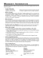
W A R R A N T Y I N F O R M AT I O N
Rockford Corporation offers a limited warranty on Rockford Fosgate products on the
following terms:
• Length of Warranty
3 years on electronics
2 years on source units
90 days on electronic B-stock (receipt required)
30 days on speaker B-stock (receipt required)
• What is Covered
This warranty applies only to Rockford Fosgate products sold to consumers by
Authorized Rockford Fosgate Dealers in the United States of America or its
possessions. Product purchased by consumers from an Authorized Rockford
Fosgate Dealer in another country are covered only by that country’s Distributor
and not by Rockford Corporation.
• Who is Covered
This warranty covers only the original purchaser of Rockford product purchased
from an Authorized Rockford Fosgate Dealer in the United States. In order to
receive service, the purchaser must provide Rockford with a copy of the receipt
stating the customer name, dealer name, product purchased and date of purchase.
• Products found to be defective during the warranty period will be repaired or
replaced (with a product deemed to be equivalent) at Rockford's discretion.
• What is Not Covered
1. Damage caused by accident, abuse, improper operations, water, theft
2. Any cost or expense related to the removal or reinstallation of product
3. Service performed by anyone other than Rockford or an Authorized Rockford
Fosgate Service Center
4. Any product which has had the serial number defaced, altered, or removed
5. Subsequent damage to other components
6. Any product purchased outside the U.S.
7. Any product not purchased from an Authorized Rockford Fosgate Dealer
• Limit on Implied Warranties
Any implied warranties including warranties of fitness for use and merchantability
are limited in duration to the period of the express warranty set forth above. Some
states do not allow limitations on the length of an implied warranty, so this
limitation may not apply. No person is authorized to assume for Rockford Fosgate
any other liability in connection with the sale of the product.
• How to Obtain Service
Please call 1-800-669-9899 for Rockford Customer Service. You must obtain an
RA# (Return Authorization number) to return any product to Rockford Fosgate. You
are responsible for shipment of product to Rockford.
Ship to:
Electronics
Rockford Corporation
Warranty Repair Department
2055 E. 5th Street
Tempe, AZ 85281
RA#:_________________
Ship to:
Speakers
Rockford Acoustic Design
(Receiving-speakers)
609 Myrtle N.W.
Grand Rapids, MI 49504
RA#:_________________
– 41 –
A
T
N
A
TI
M
IO
R
R
TE
O
N
FO
N
IN
A
L
IN
– 42 –
LEA DETENIDAMENTE LAS SIGUIENTES INSTRUCCIONES DE
INSTALACION DEL PRODUCTO. EVITARA POSIBLES DAÑOS A VD., AL
VEHICULO O AL PRODUCTO.
INTRODUCCION
El Punch 360.6 es un amplificador de 6 canales de 360 vatios con
caracteristicas integradas para permitir diseños de sistemas con un solo
amplificador. Dentro del amplificador hay 4 crossovers XCards y un
circuito de conmutación de señal. Estos dispositivos simplifican el
procesado de señal y permiten una distribución de la señal a medida de
las necesidades para cada canal. También están integrados un conmutador
de fase y un circuito ecualizador de graves diseñados para optimizar el
ajuste del sistema. El esfuerzo de ingeniería realizado en el diseño del
Punch 360.6 se hace patente al ver la facilidad con que es instalado un
sistema de tres vías usando un mínimo número de componentes.
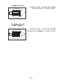
UBICACIÓN PARA EL MONTAJE
Montaje en el Malatero
Monte el amplificador verticalmente con las lineas del radiador orientadas
de arriba hacia abajo. De esta manera conseguira la mejor ventilacion.
Montaje en el Compartimento de Pasajeros
El montaje en el compartimento de pasajeros sera eficiente en funcion
de la ventilacion que tenga el amplificador. Si va a instalar el amplificador
bajo un asiento deberá dejar al menos 2.5cm libres sobre la carcasa del
amplificador.
Instalacion
Por seguridad, desconecte el terminal negativo de la bateria antes de
comenzar la instalacion.
Terminal B+
El cable B+ debe ir provisto de un fusible a una distancia no mayor de
45cm de la bateria. Prepare el cable e instale el portafusibles en el
compartimento del motor. Las conexiones han de ser impermeables.
Terminal GND
Prepare un trozo de cable para usarlo como toma de masa. Prepare un
punto de masa en el chasis rascando y eliminando la pintura de la
superficie de metal y limpielo de toda suciedad asegure el cable al chasis
con un tornillo.
Terminal REM
Conecte el cable REM a un punto de +12V con mutable. La señal se suele
coger de la salida auto antena del radio cassette si este no tiene salida
remote.
– 43 –
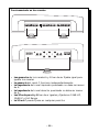
El circuito de conmutación de señal permite distribuir las entradas RCA
a las salidas de varias diferentes maneras. La orientación de ambos
conmutadores configura la distribución de señal. Los conmutadores
pueden ser posicionados en las siguientes configuraciones.
Configuración n°1
XCard
C
XCard
B
XCard
B
XCard
A
–180°
0°
Entrada canal A => Salida canal A
Entrada canal B => Salida canal B
Canal A y B sumados => Salida canal C
Configuración n°2
XCard
C
XCard
B
XCard
B
XCard
A
–180°
0°
Configuración n°3
Canal C puente
XCard
C
XCard
B
XCard
B
XCard
A
Entrada canal A => Salida canal A
Entrada canal B => Salida canal B
Entrada canal C => Salida canal C
Entrada canal A => Salida canal A
Entrada canal B => Salida canal B
Entrada canal C (mono) => Salida canal C
–180°
0°
Configuración n°4
Entrada canal A => Salida canal A, B y C
XCard
C
XCard
B
XCard
B
XCard
A
–180°
0°
– 44 –
E SPAÑOL
UTILIZACION DEL CIRCUITO DE CONMUTACION
DE SEÑAL
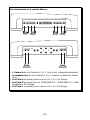
Configuración n°5
Entrada canal A => Salida canal A y B
Entrada canal C => Salida canal C
XCard
C
XCard
B
XCard
B
XCard
A
–180°
0°
Configuración n°6
Canal C puente
XCard
C
XCard
B
XCard
B
XCard
A
–180°
0°
Entrada canal A => Salida canal A y B
Entrada canal C (mono) => Salida canal C
– 45 –
Funcionamiento en tres canales
–
L
+
–
Ch. B
R
+
REM
Dual B+
Dual GND
Ch. B
–
+
L
–
Ch. A
+
+
R
–
+
4 ohm min.
–
Ch. A
4 ohm min.
R
R
R
LED
+
L
Ch. C
–
Ch. C Ch. C
Bass EQ Gain L
Ch. B
Gain
L
L
Ch. C
Ch. B
Ch. A
Gain
+
R –
Ch. C
Ch. A
–
+
4 ohm min.
• Las ganancias de los canales A y B han de ser fijadas igual para
igualar los canales
• La ganancia del canal C funciona independientemente
• La impedancia del canal izquierdo puenteado no debe ser menor
de 4Ω
• La impedancia del canal derecho puenteado no debe ser menor
de 4Ω
• Las XCards para A y B han de er iguales y fijadas en 12dB HP,
12dB LP o Full Range
• La XCard C puede fijarse en cualquier posición
– 46 –
Funcionamiento en 6 canales Estereo
–
L
+
–
Ch. B
–
–
Rear
+
R
+
REM
Dual B+
Dual GND
+
Ch. B
–
+
–
+
2 ohm min.
2 ohm min.
L
+
Ch. A
Front
–
R
–
+
2 ohm min.
R
R
Ch. A
–
2 ohm min.
R
LED
+
L
–
Ch. C Ch. C
Bass EQ Gain L
Ch. C
+
Ch. B
Gain
L
L
Ch. C
Ch. B
+
Ch. A
Gain
R –
Ch. C
Ch. A
+
–
2 ohm min.
–
2 ohm min.
• L Ganancia de los canales A, B y C funcionan independientemente
• La Impedancia para los canales A, B y C estereo no debe ser menor
de 2Ω
• La XCard A se puede posicionar en HP, LP o Full Range
• La XCard B se puede fijar en 12dB/24dB HP, 12dB/24dB LP o 12dB
Bandpass o Full Range
• La XCard C se puede posicionar en HP, LP o Full Range
– 47 –
ATTENTION: Veuillez lire les instructions suivantes pour l'installation de cet
amplifcateur. Ne pas les suivre pourrait causer des blessures ou endommager
le véhicule.
INTRODUCTION
MONTAGE
Montage dans le coffre
Monter l'amplificateur verticalement avec les rainures de haut en bas ce
qui lui permet de refroidir plus facilement.
Montage dans l'habitacle
Monter l'amplificateur dans l'habitacle ne pose aucun problème, du
moment qu'il y ait assez d'air pour le refroidir. Si vous montez l'ampli
en dessous du siège, prévoyez 3 cm d'air autour du radiateur.
Installation
Pour votre sécurité, déconnectez la borne négative de la batterie du
véhicule avant de commencer l'installation.
Terminal B+
Il est impératif qu'il y ait un fusible sur le câble pour la connexion à la
masse. Préparez le châssis en grattant la peinture de la surface métallique
et nettoyez la saleté et l'huile. Attachez le câble au châssis avec une vis.
Terminal GND
Préparez une longueur de câble pour la connexion à la masse. Préparez
le châssis en grattant la peinture de la surface métallique et nettoyez la
saleté et l'huile. Attachez le câble au châssis avec une vis.
Terminal REM
Connectez le fil REM à une commande 12 volts positive de la source. La
commande 12 volts est habituellement prise sur la sortie antenne
électrique de la source ou la commande accessoire. Si la source ne
dispose pas de ces sorties, nous vous recommandons d'installer un
interrupteur qui fournira un positif 12 volts au REM de l'amplificateur.
– 48 –
FRANÇAIS
Le Punch 360.6, est un amplificateur à 6 canaux de 360 watts avec des
caractéristiques reprises aux amplificateurs 2 canaux. Quatre cartes de
filtrage sont intégrées dans l'ampli ainsi qu'un réseau de commutation
du signal. Ces caractéristiques simplifient le traitement du signal et
permettent une configuration personnalisée de la distribution du signal
à chaque paire de canaux. Afin d'améliorer le réglage de votre système
nous avons également intégré un commutateur de phase et un circuit
d'égalisation des basses. Le développment du Punch 360.6 montre à
quel point un système 3 voies de qualité peut être facilement installé tout
en utilisant un minimum de composants.
UTILISATION DU
RÉSEAU DE COMMUTATION
DU SIGNAL
Le réseau de commutation du signal permet au signal provenant des
RCA e'entrée d'être distribué vers les sorties dans de multiple configurations. L'orientation des deux commutateurs configure la distribution de signal. Les commutateurs peuvent être orientés afin d'obtenir
les configurations suivantes:
Configuration #1
XCard
C
XCard
B
XCard
B
XCard
A
–180°
0°
entrée A => sortie A
entrée B => sortie B
somme des entrées A et B => sortie C
Configuration #2
XCard
C
XCard
B
XCard
B
XCard
A
entrée A => sortie A
entrée B => sortie B
entrée C => sortie C
–180°
0°
Configuration #3
(E-Z bridge canal C)
XCard
C
XCard
B
XCard
B
XCard
A
entrée A => sortie A
entrée B => sortie B
entrée C (L mono) => sortie C
–180°
0°
Configuration #4
entrée A => sortie A, B et C
XCard
C
XCard
B
XCard
B
XCard
A
–180°
0°
– 49 –
Configuration #5
entrée A => sortie A et B
entrée C => sortie C
XCard
C
XCard
B
XCard
B
XCard
A
–180°
0°
Configuration #6
(E-Z bridge canal C)
XCard
C
XCard
B
XCard
B
XCard
A
entrée A => sortie A et B
entrée C (L mono) => sortie C
–180°
0°
– 50 –
Configuration à 3 canaux
–
L
+
–
Ch. B
R
+
REM
Dual B+
Dual GND
Ch. B
–
+
L
–
Ch. A
+
+
R
–
Ch. A
–
+
4 ohm min.
4 ohm min.
R
R
R
LED
+
L
Ch. C
–
Ch. C Ch. C
Bass EQ Gain L
Ch. B
Gain
L
L
Ch. C
Ch. B
Ch. A
Gain
+
R –
Ch. C
Ch. A
–
+
4 ohm min.
• Les controles de gain des canaux A et B sont réglés de manière
égale pour équilibrer le subwoofer
• Les controles de gain des canaux C sont indépendants
• L'impédance pour le canal bridgé de gauche doit être de 4Ω
minimum
• L'impédance pour le canal bridgé de droit doit être de 4Ω minimum
• L'impédance pour le canal bridgé C doit être de 4Ω minimum
• Les cartes de filtrage A et B doivent être réglées de manière
identique: 12dB passe-haut, passe-bas ou full range
• La carte de filtrage C doit étre réglée en passe-haut, passe-bas ou
full range
– 51 –
Configuration à 6 canaux
–
L
+
–
Ch. B
–
–
Rear
+
R
+
–
2 ohm min.
REM
Dual B+
Dual GND
+
Ch. B
L
–
+
Ch. A
+
+
2 ohm min.
Front
–
R
–
+
2 ohm min.
R
R
Ch. A
–
2 ohm min.
R
LED
+
L
–
Ch. C Ch. C
Bass EQ Gain L
Ch. C
+
Ch. B
Gain
L
L
Ch. C
Ch. B
+
Ch. A
Gain
R –
Ch. C
Ch. A
+
–
2 ohm min.
–
2 ohm min.
• Les controles de gain des canaux A, B et C sont indépendants
• L'impédance pour le canal bridgé de gauche doit être de 4Ω minimum
• L'impédance pour le canal bridgé de droit doit être de 4Ω minimum
• La carte de filtrage A peut être réglée en passe-haut, passe-bas ou
full range
• Les cartes de filtrage B peuvent être réglées en 12/24dB passe-haut,
12/24dB passe-bas, 12dB passe-bande ou full range
• La carte de filtrage C peut étre réglée en passe-haut, passe-bas ou
full range
– 52 –
BITTE LESEN SIE DIESE GEBRAUCHSANLEITUNG ZUERST SORGFÄLTIG
DURCH. DAS KANN SIE VOR DEM FALSCHEN EINSATZ, AUSFALLEN
ODER SOGAR BESCHÄDIGUNG DES PRODUKTES ODER IHRES
FAHRZEUGES SCHÜTZEN.
EINLEITUNG
Die Punch 360.6 ist ein 360 Watt, 6-Kanal Verstärker mit integrierten
Besonderheiten, um ein “ein Verstärker” System zu kreieren. Eingebaut
sind vier interne Frequenzkarten und ein schaltbares Signal Netzwerk.
Diese Besonderheiten vereinfachen die Signalbearbeitung und
ermöglichen es, jedem Kanal die “richtigen” Frequenzen zuzuteilen. Ein
Phasenumschalter und eine Bass-Equilizer Schaltung sind ebenfalls
eingebaut, um Ihr System optimal anzupassen. Die Anstrengungen der
Ingenieure lagen darin, ein vollwertiges 3-Wege System mit möglichst
wenig Komponenten zu realisieren.
EINBAUORT
Im Fahrzeugkofferraum
Der vertikale Einbau der Endstufen, das bedeutet, daβ die Kühlrippen
von oben nach unten verlaufen, gibt dem Verstärker die beste Kühlung.
Auf der Beifahrerseite
Sollte der Verstärker auf der Beifahrerseite montiert werden, so ist es sehr
wichtig, für eine ausreichende Kühlung zu sorgen. Sollte der Verstärker
z.B. unter dem Beifahrersitz montiert werden, sollte dem Kühlkörper
mindestens ein Luftspalt von 3 cm bleiben, um so für eine ausreichende
Kühlung zu sorgen.
Einbau
Zur Sicherheit klemmen Sie den Negativ-Pol der Batterie während des
gesamten Einbaues ab.
B+ Anschluss
Die Plus-Leitung MUβ ca. 40 cm nach dem Plus-Pol der Batterie abgesichert
sein. Preparieren Si die Kabellängen und montieren Sie den Sicherungshalter
im Motorraum. ALLE Verbindungen müssen wasserdicht sein.
GND Anschluss
Preparieren Sie Ihr Kabel für die Negativ Leitung (Erdung). Preparieren
Sie die Anschluβstelle des Erdungskabels, indem Sie das Metall gründlich
reinigen und vom Lack befreien. Befestigen Sie nun die Erdung an dieser
Stelle mit einer Schraube.
REM Anschluss
Verbinden Sie das Ein-und Ausschaltungskontroll-Kabel mit Ihrem
Radio (12 Volt positiv). Normalerweise verwenden Sie hierfür die Ant.Remote Ihres Radios oder ein eigens dafür vorgesehenes Kabel (AmpRemote). Sollte Ihr Radio diesen Anschluβ nicht besitzen, so verwenden
Sie eine 12 Volt Spannung, die Sie durch einen Schalter ein- und
ausschalten können.
– 53 –
BENUTZEN DES SIGNAL NETZWERKES
Das Schaltbare Signal Netzwerk erlaubt es, die Eingangssignale den
verschiedenen Ausgangen optimal zuzuteilen. Die verschiedenen
Stellungen der Schalter sind in den folgenden Beispielen dargestellt.
Beispiel #1
XCard
C
XCard
B
XCard
B
XCard
A
–180°
0°
Kanal A Eingang => Kanal A Ausgang
Kanal B Eingang => Kanal B Ausgang
Kanal A & B
Eingang addiert => Kanal C Ausgang
Beispiel #2
XCard
C
XCard
B
XCard
B
XCard
A
–180°
0°
Beispiel #3
(E-Z gebrückt Kanal C)
C
XCard
B
XCard
B
XCard
A
–180°
0°
Kanal A Eingang => Kanal A Ausgang
Kanal B Eingang => Kanal B Ausgang
Kanal C (L mono) Eingang => Kanal C
Ausgang
Beispiel #4
Kanal A Eingang => Kanal A, B & C Ausgang
XCard
C
XCard
B
XCard
B
XCard
A
–180°
0°
– 54 –
DEUTSCH
XCard
Kanal A Eingang => Kanal A Ausgang
Kanal B Eingang => Kanal B Ausgang
Kanal C Eingang => Kanal C Ausgang
Beispiel #5
Kanal A Eingang => Kanal A & B Ausgang
Kanal C Eingang => Kanal C Ausgang
XCard
C
XCard
B
XCard
B
XCard
A
–180°
0°
Beispiel #6
(E-Z gerbrückt Kanal C)
XCard
C
XCard
B
XCard
B
XCard
A
–180°
0°
Kanal A Eingang => Kanal A & B Ausgang
Kanal C (L mono) Eingang => Kanal C
Ausgang
– 55 –
3-Kanal Operation
–
L
+
–
Ch. B
R
+
REM
Dual B+
Dual GND
Ch. B
–
+
L
–
Ch. A
+
+
R
–
Ch. A
–
+
4 ohm min.
4 ohm min.
R
R
R
LED
+
L
Ch. C
–
Ch. C Ch. C
Bass EQ Gain L
Ch. B
Gain
L
L
Ch. C
Ch. B
Ch. A
Gain
+
R –
Ch. C
Ch. A
–
+
4 ohm min.
• Gain-Kontrolle für die Kanäle A & B gleich einstellen, um die
Subwoofer auszubalancieren
• Gain-Kontrolle für Kanal C arbeitet unabhängig davon
• Die Impedanz für den gebrückten linken Kanal sollte minimum
4Ω betragen
• Die Impedanz für den gebrückten rechten Kanal sollte minimum
4Ω betragen
• Die Impedanz für den gebrückten C Kanal sollte minimum 4Ω
betragen
• Die Aktivweichen-Modul A & B sollten gleich gesteckt werden,
als 12dB Hochpass, 12dB Tiefpass oder Full Range
• Das Aktivweichen-Modul für Kanal C sollte auf Hochpass,
Tiefpass oder Full Range gesteckt werden
– 56 –
6-Kanal Stereo Operation
–
L
+
–
Ch. B
–
–
Rear
+
R
+
REM
Dual B+
Dual GND
+
Ch. B
–
+
–
+
2 ohm min.
2 ohm min.
L
+
Ch. A
Front
–
R
–
+
2 ohm min.
R
R
Ch. A
–
2 ohm min.
R
LED
+
L
–
Ch. C Ch. C
Bass EQ Gain L
Ch. C
+
Ch. B
Gain
L
L
Ch. C
Ch. B
+
Ch. A
Gain
R –
Ch. C
Ch. A
+
–
2 ohm min.
–
2 ohm min.
• Gain-Kontrolle für die Kanäle A, B & C arbeiten unabhängig
voneinander
• Die Impedanz für die Stereo-Kanäle A, B & C sollten mindestens
2Ω begragen
• Das Aktivweichen-Modul für Kanal A kann auf Hochpass,
Tiefpass oder Full Range gesteckt werden
• Das Aktivweichen-Modul für Kanal B kann auf 12dB/24dB
Hochpass, 12dB/24dB tiefpass oder Full Range gesteckt werden
• Das Aktivweichen-Modul für Kanal C kann auf Hochpass,
Tiefpass oder Full Range gesteckt werden
– 57 –
ATTENZIONE: SI PREGA DI LEGGERE LE SEGUENTI ISTRUZIONI PER
L'INSTALLAZIONE DI QUESTO PRODOTTO. IL NON SEGUIRLE POTREBBE
RISULTARE SERIAMENTE DANNOSO PER LA PERSONA O PER IL VEICOLO.
INTRODUZIONE
Il Punch 360.6 é un amplificatore da 360 watt totali e 6 canali progettato
per essere installato come un singolo apparato. Al suo interno trovano
posto caratteristiche che consentono questa elevatissima versatilitá,
come le 4 XCard e la rete di selezione degli ingressi. tutte queste
caratteristiche semplificano il processo del segnale audio e permettono
all'utilizzatore di smistare il segnale a ciascuna coppia di canali. É
presente anche uno switch di inversione fase e un circuito di
equalizzazione in gamma bassa per agevolare le operazioni di taratura
del sistema. Lo sforzo ingegneristico applicato al 360.5 dimostra come
un sistema a 3 vie possa essere installato con facilitá mantenendo ridotto
il numero di componenti.
DOVE POSIZIONARLO
Nel Bagagliaio
Montando l'amplificatore su una superficie in verticale con le alette
direzionate dall'alto verso il basso vi garantirá un miglior raffreddamento
dell'amplificatore.
Nell'abitacolo
Montandop l'amplificatore nell'abitacolo si avrá un funzionamento
regolare se si garantisce un flusso d'aria sufficiente. Per l'installazione
sotto un sedile, é necessario avere uno spazio di almeno 3 cm attorno
a tutto l'amplificatore.
Installazione
Per sicurezza, scollegare il polo negativo della batteria dell'auto prima
di iniziare l'installazione.
Terminale B+ (cavo positivo)
Il cavo positivo deve essere protetto da un fusibile a non piú di 45 cm
dalla batteria. Terminare il cavo e installare il fusibile nel vano motore.
Tutte le connessioni devono essere a prova d'acqua.
Terminale GND (cavo negativo)
Decidere la lunghezza del cavo e terminarlo. Preparare la massa
grattando la vernice dal telaio dell'auto ed eliminando tracce di olio o
sporco. Fissare il cavo di massa al telaio con una vite.
ITALIANO
Terminale REM (Consenso di accensione)
Collegare il cavo REM ad un positivo presente solo ad autoradio accesa
(normalmente il cavo pilota dell'antenna elettrica o il cavo accessori
dell'autoradio). Se la sorgente non dovesse essere equipaggiata con
queste uscite, la soluzione raccomandabile é di inserire un interruttore
su un cavo positivo e connettersi all'amplificatore.
– 58 –
IMPIEGARE LA RETE DI SELEZIONE DEGLI INGRESSI
La rete di selezione degli ingressi permette al segnale RCA di essere
diretto alle uscite in molti modi distinti. La posizione di entrambi i
selettori stabilisce la configurazione adottata. I selettori possono
essere configurati nei modi seguenti:
Configurazione #1
XCard
C
XCard
B
XCard
B
XCard
A
–180°
0°
Ingresso A => Uscita A
Ingresso B => Uscita B
Ingressi A e B sommati => Uscita C
Configurazione #2
XCard
C
XCard
B
XCard
B
XCard
A
–180°
0°
Ingresso A => Uscita A
Ingresso B => Uscita B
Ingresso C => Uscita C
Configurazione #3
(E-Z bridge Uscita C)
XCard
C
XCard
B
XCard
B
XCard
A
–180°
0°
Ingresso A => Uscita A
Ingresso B => Uscita B
Ingresso C (L mono) => Uscita C
Configurazione #4
Ingresso A => Uscita A, B, C
XCard
C
XCard
B
XCard
B
XCard
A
–180°
0°
– 59 –
Configurazione #5
Ingresso A => Uscita A, B
Ingresso C => Uscita C
XCard
C
XCard
B
XCard
B
XCard
A
–180°
0°
Configurazione #6
(E-Z bridge Uscita C)
Ingresso A => Uscita A, B
Ingresso C (L mono) => Uscita C
XCard
C
XCard
B
XCard
B
XCard
A
–180°
0°
– 60 –
Funzionamento a 3 canali
–
L
+
–
Ch. B
R
+
REM
Dual B+
Dual GND
Ch. B
–
+
L
–
Ch. A
+
+
R
–
Ch. A
–
+
4 ohm min.
4 ohm min.
R
R
R
LED
+
L
Ch. C
–
Ch. C Ch. C
Bass EQ Gain L
Ch. B
Gain
L
L
Ch. C
Ch. B
Ch. A
Gain
+
R –
Ch. C
Ch. A
–
+
4 ohm min.
•
•
•
•
•
•
I gain dei canali A e B regolati identici per bilanciare il subwoofer
Il gain dei canale C opera indipendentemente
L'impedenza per il canale a ponte sinistro deve essere minimo 4Ω
L'impedenza per il canale a ponte destro deve essere minimo 4Ω
L'impedenza per il canale C deve essere minimo 4Ω
Le XCard A & B devono essere identiche e posizionate allo stesso
modo, Passa alto 12dB/ott, Passa basso 12dB/ott o gamma intera
• La XCard C puó essere indipendentemente posizionata Passa alto,
Passa basso o gamma intera
– 61 –
Funzionamento a 6 canali stereo
–
L
+
–
Ch. B
–
–
Rear
+
R
+
–
2 ohm min.
REM
Dual B+
Dual GND
+
Ch. B
L
–
+
Ch. A
+
+
2 ohm min.
Front
–
R
–
+
2 ohm min.
R
R
Ch. A
–
2 ohm min.
R
LED
+
L
–
Ch. C Ch. C
Bass EQ Gain L
Ch. C
+
Ch. B
Gain
L
L
Ch. C
Ch. B
+
Ch. A
Gain
R –
Ch. C
Ch. A
+
–
2 ohm min.
–
2 ohm min.
• I gain per i canali A, B, C operano in modo indipendente
• L'impedenza per il canali stereo A, B, C deve essere minimo 2Ω
• La XCard A puó essere impiegata Passa alto, Passa basso o
gamma intera
• La XCard B puó essere impiegata Passa alto 12/24dB/ott, Passa
basso 12/24dB/ott, Passa banda 12dB/ott o gamma intera
• La XCard C puó essere impiegata come Passa alto, Passa basso o
gamma intera
– 62 –
NOTES
– 63 –
NOTES
– 64 –
MADE IN THE USA
This product is designed, developed and assembled in the USA by a dedicated
group of American workers. The majority of the components used in the
construction of this product are produced by American companies. However, due
to the global nature of their manufacturing facilities and the loudspeaker parts
industry in general, some parts may be manufactured in other countries.
Rockford Fosgate
Rockford Corporation
546 South Rockford Drive
Tempe, Arizona 85281 U.S.A.
In U.S.A., (602) 967-3565
In Europe, Fax (49) 4207-801250
In Japan, Fax (81) 559-79-1265
9/96
MAN-1364-A