1
User’s Manual
2004-04-02
Closer to Real,
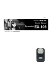
Dynamixel
DX-116
DYNAMIXEL DX-116
Contents
1. Summary
1-1. Overview & Characteristics of DX-116
Page 2
1-2. Main Specification
Page 4
2. Dynamixel Assembly
2-1. Mechanical Parts Assembly
Page 5
2-2. Connector Assembly
Page 5
2-3. Dynamixel Wiring
Page 6
3. Communication Protocol
3-1. Communication Overview
Page 9
3-2. Instruction Packet
Page 10
3-3. Status Packet
Page 10
3-4. Control Table
Page 13
4. Instruction Set and Examples
4-1. WRITE _DATA
Page 20
4-2. READ _DATA
Page 21
4-3. REG_WRITE and ACTION
Page 22
4-4. PING
Page 23
4-5. RESET
Page 24
5. Example
Page 25
Appendix
Page 32
1
English Translation by: Tribotix Pty Ltd
www.tribotix.com
DYNAMIXEL DX-116
1. Dynamixel DX-116
1-1. Overview & Characteristics of DX-116
Dynamixel DX-116
The Dynamixel is a smart actuator which incorporates a precision servo
motor and a control unit with networking functionality, all in a single unit.
Despite its compact size, it can produce high torque and has been
manufactured using high quality materials to provide the necessary strength
and structural resilience. It can also detect and act upon internal conditions
such as temperature and over-current .
The Dynamixel has many advantages over similar products:-
Precise Control
Control position and speed with fine angular resolution (1024 divisions)
Compliance Driving
Control the degree of elastic force in position control.
Feedback
Feedback for angular position, speed and load size.
Alarm System
Not only does the Dynamixel warn of a deviation from the user defined
ranges (e.g. internal temperatures, torques, voltages etc), but it also
automatically deals with the problems as they occur.
Communication
Daisy chain connection with support for communication speeds of up to
1MBPS.
High Efficiency Motor
Dynamixel uses the RE–MAX Series Coreless DC Motors from Swiss Maxon
Motor which boasts high output torque and excellent acceleration.
Distributed Control
The main processor requires very few resources to control multiple
Dynamixels since the movement schedule requires only a single command
packet.
High Quality Enclosure
The high quality plastic body ensures structural integrity under all
operational conditions
2
English Translation by: Tribotix Pty Ltd
www.tribotix.com
DYNAMIXEL DX-116
Metal Gears
All the gear sets are made of metal to ensure extreme durability.
Axis Bearing
A bearing is used on the final axis to ensure there is no loss of efficiency
during heavily loaded conditions.
Status LED
A LED indicates error status.
3
English Translation by: Tribotix Pty Ltd
www.tribotix.com
DYNAMIXEL DX-116
1-2. Main Specification
Holding Torque
31.5kg·cm (18V) ~ 21 kg·cm (12V)
Reduction ratio
1/140
Speed
0.084sec/60° (18V) ~ 0.125sec/60° (12V)
Resolution
0.35°
Operating Angle
300°
Voltage
12V~18V (Recommended voltage: 14~15V)
Max. Current
1200mA
Operating Temp.
-5℃ ~ +85℃
Weight
66g
Command Signal
Digital Packet
Protocol Type
Half duplex Asynchronous Serial Communication (8bit,1stop,No Parity)
Link (Physical)
RS 485 Multi Drop (daisy chain configuration)
ID
254 ID (0~253)
Communication Speed 7343bps ~ 1 Mbps
Feedback
Position, Temperature, Load, Input Voltage, etc.
Material
Full Metal Gear, Engineering Plastic Body
Motor
Swiss MAXON Motor RE-MAX (best level)
4
English Translation by: Tribotix Pty Ltd
www.tribotix.com
DYNAMIXEL DX-116
2. Installation of Dynamixel
2-1. Mechanical Parts Assembly
Mechanical Parts of Dynamixel are assembled as follows:
Horn
Nut(8EA)
Screw for Horn
Screw for mount(8EA)
The 8 sets of Nuts & Screws are only used when a Dynamixel is mounted to
other equipment.
2-2. Connector Assembly
Assemble the connectors as shown below. Attach the wires to the terminals
using the correct crimping tool. If you do not have access to an appropriate
crimper, solder the terminals to the wires to ensure that they do not become
loose during operation.
5
English Translation by: Tribotix Pty Ltd
www.tribotix.com
DYNAMIXEL DX-116
2-3. Wiring of Dynamixel
Pin Assignment
Pin assignments of the connectors are as follows:-
Pin 1: GND
Pin 2: +12V~18V
Pin 4: D- (RS485 Signal)
Connect the same pin numbers as shown below.
Main
Controller
Main Controller
4
3
2
1
Wire Link
Pin 4
3
2
1
Pin 1
2
3
4
Pin 3: D+ (RS485 Signal)
The Main Controller must support RS485 to control the Dynamixel. A proprietary
Controller may be utilised but the Cycloid-M2 board is recommended.
PC LIMK
A PC can be used to control the Dynamixel via the Cycloid-M2 Board.
RS485
Level
RS232
Level
PC
Stand Alone
Cycloid-M2
Dynamixels
The Cycloid-M2 Board can be directly mounted on the robots.
6
English Translation by: Tribotix Pty Ltd
www.tribotix.com
DYNAMIXEL DX-116
Cycloid-M2 Board on Robot
Please refer to the Cycloid-M2 Board manual for more details.
Connection to UART
To control the Dynamixel, the main Controller needs to convert the signals to
RS485. The recommended schematic configuration is as follows:-
전원은 Main Controller의 Molex4P Connector의 Pin1,Pin2를 통하여 Dynamixel로
공급되어진다.
Signal DIRECTION485 determines the data direction as follows: If DIRECTION485 is High: the signal TxD is output as D+,D If DIRECTION485 is Low: signal D+,D- is input as RxD
7
English Translation by: Tribotix Pty Ltd
www.tribotix.com
DYNAMIXEL DX-116
RS485
A multi-dropped RS485 (IEEE485) network is established from the main
controller. Data Packets are then issued through this single portal.
Main
Controller
[RS485 Multi Drop Link]
Please note that caution should be applied when connecting the Dynamixel units to ensure that the pin
assignments are correct. Always check the current consumption. The standby current consumption of a
Dynamixel unit should be less than 50mA.
Connection Status
When power is first applied the Dynamixel LED will blink twice to confirm its
healthy status.
Inspection
If the above operation was not successful, then check the connector pin
assignment and the voltage/current limit of the power supply.
8
English Translation by: Tribotix Pty Ltd
www.tribotix.com
DYNAMIXEL DX-116
3. Communication Protocol
3-1. Communication Overview
Packet
The Main Controller communicates with the Dynamixel by sending and receiving
data packets. There are two types of packets, the Instruction Packet (Main
Controller to Dynamixel) and the Status Packet (Dynamixel to Main Controller)
Instruction Packet
Main
Controller
Communication
Status Packet
For the system connection below, if the main controller sends an instruction
packet with the ID set to N, only the Dynamixel with this ID value will return its
respective status packet and perform the required instruction.
Instruction Packet(ID=N)
Main
Controller
ID=0
ID=1
ID=N
Status Packet(ID=N)
Unique ID
Communication problems will arise if multiple Dynamixel's have the same ID
value. This will cause multiple packets to be sent simultaneously resulting in
packet collisions. It is imperative that ID values are unique within each data
network.
Protocol
The Asynchronous Serial Communication word consists of 8 bits, 1 Stop bit and
no parity.
9
English Translation by: Tribotix Pty Ltd
www.tribotix.com
DYNAMIXEL DX-116
3-2. Instruction Packet
The structure of the Instruction Packet is as follows:
Instruction Packet
OXFF 0XFF ID LENGTH INSTRUCTION PARAMETER1 …PARAMETER N CHECK
SUM
The packet byte definitions are as follows:-
0XFF 0XFF
Two 0XFF bytes indicate the start of an incoming packet.
ID
Unique ID of a Dynamixel. The ID can range from 0X00 to 0XFD (254 IDs are
available)
Broadcasting ID
ID 0XFE is the Broadcast ID which is assigned to all of the connected
Dynamixel’s. Status packets will not be returned with a broadcasting ID.
LENGTH
The length of the Status Packet. The value is “Parameter number (N) + 2”
INSTRUCTION
The instruction for the Dynamixel to perform.
PARAMETER0…N
Used if there is additional information to be sent other than the Instruction.
CHECK SUM
The calculation method for the ‘Check Sum’ is as follows:
Check Sum = ~( ID + Length + Instruction + Parameter1 + … Parameter N )
If the calculated value is bigger than 255, the lower byte becomes the checksum.
~ represents the Not or complement operation
3-3. Status Packet
The Status Packet is the response packet from the Dynamixel to the Main
Controller after receiving an instruction packet. The structure of Status Packet
is as follows:-
10
English Translation by: Tribotix Pty Ltd
www.tribotix.com
DYNAMIXEL DX-116
OXFF 0XFF ID LENGTH ERROR PARAMETER1 PARAMETER2…PARAMETER N
CHECK SUM
The meaning of each byte within the packet is as follows:-
0XFF 0XFF
Two 0XFF bytes indicate the start of a packet
ID
ID of the Dynamixel which is returning the packet.
LENGTH
The length of the Status Packet. The value is “Parameter number (N) + 2”.
ERROR
Dynamixel communication error flags. The meaning of each bit is as follows:
Bit
Na me
De ta ils
Bit 7
0
-
Bit 6
Ins tr uc tion
Er ror
Se t to 1 if a n unde fine d ins tr uc tion is give n without
the r e g_wr ite ins tr uc tion.
Bit 5
Ove r loa d
Er r or
Se t to 1 if the s pe cifie d tor que c an't c ontr ol the
loa d.
Bit 4
Che c ks um
Er ror
Se t to 1 if the c he c ks um of the intr uc tion pa c ke t is
inc or r e c t
Bit 3
Ra nge Er r or
Se t to 1 if the intr uc tion is out of the us a ge ra nge
Bit 2
Ove r he a ting
Er ror
Bit 1
Angle Limit
Er r or
Bit 0
Se t a s 1 if the inte r na l te mpe r a tur e of Dyna mix e l is
out of the ope r a tive r a nge a s s e t in the c ontr ol
ta ble .
Se t a s 1 if the Goa l Pos ition is s e t outs ide of the
r a nge be twe e n CW Angle Limit a nd CCW Angle
Limit.
Input Volta ge Se t to 1 if the volta ge is out of the ope r a tive r a nge
Er ror
s e t in the c ontr ol ta ble
PARAMETER0…N
Used when additional information is required.
CHECK SUM
Calculation method of ‘Check Sum’is as follows:
Check Sum = ~( ID + Length + Instruction + Parameter1 + … Parameter N )
If the calculated value is bigger than 255, the lower byte becomes the checksum.
~ represents the Not or complement operation
11
English Translation by: Tribotix Pty Ltd
www.tribotix.com
DYNAMIXEL DX-116
3-4. Control
Table
EEPROM
Area
RAM
Area
Addre ss
0(0X00)
1(0X01)
2(0X02)
3(0X03)
4(0X04)
5(0X05)
6(0X06)
7(0X07)
8(0X08)
9(0X09)
10(0x0A)
11(0X0B)
12(0X0C)
13(0X0D)
14(0X0E)
15(0X0F)
16(0X10)
17(0X11)
18(0X12)
19(0X13)
20(0X14)
21(0X15)
22(0X16)
23(0X17)
24(0X18)
25(0X19)
26(0X1A)
27(0X1B)
28(0X1C)
29(0X1D)
30(0X1E)
31(0X1F)
32(0X20)
33(0X21)
34(0X22)
35(0X23)
36(0X24)
37(0X25)
38(0X26)
39(0X27)
40(0X28)
41(0X29)
42(0X2A)
43(0X2B)
44(0X2C)
45(0X2D)
46[0x2E)
47[0x2F)
48[0x30)
49[0x31)
Ite m
Mo de l Numbe r(L)
Mo de l Numbe r(H)
Ve rsion o f Firmwa re
ID
Ba ud Ra te
Re turn De la y Time
CW Angle Limit(L)
CW Angle Limit(H)
CCW Angle Limit(L)
CCW Angle Limit(H)
(Re se rve d)
the Highe st Limit Te mpe ra ture
the Lo we st Limit Vo lta ge
the Highe st Limit Vo lta ge
Ma x Torque (L)
Ma x Torque (H)
Sta tus Re turn Le ve l
Ala rm LED
Ala rm Shutdo wn
(Re se rve d)
Do wn Ca libra tio n(L)
Do wn Ca libra tio n(H)
Up Ca libra tio n(L)
Up Ca libra tio n(H)
To rque Ena ble
LED
CW Co mplia nc e Ma rgin
CCW Co mplia nc e Ma rgin
CW Co mplia nc e Slo pe
CCW Co mplia nc e Slo pe
Go a l Po sitio n(L)
Go a l Po sitio n(H)
Mo ving Spe e d(L)
Mo ving Spe e d(H)
To rque Limit(L)
To rque Limit(H)
Pre se nt Po sitio n(L)
Pre se nt Po sitio n(H)
Pre se nt Spe e d(L)
Pre se nt Spe e d(H)
Pre se nt Lo a d(L)
Pre se nt Lo a d(H)
Pre se nt Vo lta ge
Pre se nt Te mpe ra ture
Re giste re d Instruc tio n
(Re se rve d)
Mo ving
Lo c k
Punc h(L)
Punc h(H)
Ac c e ss
RD
RD
RD
RD,WR
RD,WR
RD,WR
RD,WR
RD,WR
RD,WR
RD,WR
RD,WR
RD,WR
RD,WR
RD,WR
RD,WR
RD,WR
RD,WR
RD,WR
RD,WR
RD
RD
RD
RD
RD,WR
RD,WR
RD,WR
RD,WR
RD,WR
RD,WR
RD,WR
RD,WR
RD,WR
RD,WR
RD,WR
RD,WR
RD
RD
RD
RD
RD
RD
RD
RD
RD,WR
RD
RD,WR
RD,WR
RD,WR
Initia l Va lue
116(0x74)
0(0x00)
?
1(0x01)
34(0x22)
80(0x50)
0(0x00)
0(0x00)
255(0xFF)
3(0x03)
0(0x00)
100(0x64)
60(0X3C)
190(0xBE)
255(0XFF)
3(0x03)
2(0x02)
4(0x04)
4(0x04)
0(0x00)
?
?
?
?
0(0x00)
0(0x00)
0(0x00)
0(0x00)
32(0x20)
32(0x20)
[Addr36]va lue
[Addr37]va lue
0
0
[Addr14] va lue
[Addr15] va lue
?
?
?
?
?
?
?
?
0(0x00)
0(0x00)
0(0x00)
0(0x00)
32(0x20)
0(0x00)
12
English Translation by: Tribotix Pty Ltd
www.tribotix.com
DYNAMIXEL DX-116
Control Table
The Control Table consists of data for conditions and movement of the
Dynamixel. By writing the values in the control table, you can move the
Dynamixel and detect the condition of the Dynamixel.
RAM and EEPROM
The data values for the RAM Area will be set to the default initial values on
power on. The data values for the EEPROM Area are non-volatile and will be
available next power on.
Initial Value
The Initial Value column of the control table shows the Factory Default Values
for the case of EEPROM Area Data. For the RAM Area Data, the initial value
column gives the power on data values.
Please note the following meanings for data assigned to each address in the
control table.
Address 0x00,0x01
Model Number. In the case of the DX-116, the value is 0X0074(116).
Address 0x02
Firmware Version.
Address 0x03
ID. Unique ID number to identify the Dynamixel. Different ID’s are required to
be assigned to “linked” Dynamixels.
Address 0x04
Baud Rate. Determines the Communication Speed. The Calculation method is:Speed(BPS) = 2000000/(Address4+1)
Data Value as per Major Baud Rate
Addr e s s 4
1
3
4
7
9
16
34
103
207
BP S Se t
1 00 0 00 0 .0
50 0 00 0 .0
40 0 00 0 .0
25 0 00 0 .0
20 0 00 0 .0
11 7 64 7 .1
5 7 14 2 .9
1 9 23 0 .8
9 61 5.4
T a r ge t BP S
10 00 0 00 .0
5 00 0 00 .0
4 00 0 00 .0
2 50 0 00 .0
2 00 0 00 .0
1 15 2 00 .0
57 6 00 .0
19 2 00 .0
9 6 00 .0
Er r or
0 .0 0 0%
0 .0 0 0%
0 .0 0 0%
0 .0 0 0%
0 .0 0 0%
- 2 .1 2 4%
0 .7 9 4%
- 0 .1 6 0%
- 0 .1 6 0%
Note
A maximum Baud Rate error of 3% is within the UART communication tolerance.
Address 0x05
Return Delay Time. The time taken after sending the Instruction Packet, to
13
English Translation by: Tribotix Pty Ltd
www.tribotix.com
DYNAMIXEL DX-116
receive the requested Status Packet. The delay time is given by 2uSec *
Address5 value.
Address 0x06,0x07,0x08,0x09
Operating Angle Limit.
Set the operating angle to restrict the Dynamixel’s angular range. The Goal
Position needs to be within the range of:CW Angle Limit <= Goal Position <= CCW Angle Limit
An Angle Limit Error will occur if this relationship is not satisfied.
Address 0x0B
the Highest Limit Temperature. The upper limit of the Dynamixel’s operative
temperature. If the Dynamixel’s internal temperature is higher than this value,
an Over Heating Error Bit (Bit 2 of the Status Packet) will be set. An alarm will
be set in Address 17,18. The values are in Degrees Celsius.
Address 0x0C,0x0D
the Lowest (Highest) Limit Voltage. Setting the operative upper and lower limits
of the Dynamixel’s voltages.
If the present voltage (Address42) is out of the specified range, a Voltage Range
Error bit will be set in the Status Packet and an alarm executed will be set in
Address’s 17,18. The values are 10 times the actual voltages. For example, if
the Address 12 value is 80, then the lower voltage limit is set to 8V.
Address 0x0E,0x0F, 0x22,0x23
Max Torque. The max torque output for the Dynamixel. When it is set to ‘0’,
the Dynamixel enters a Torque Free Run condition. The Max Torque (Torque
Limit) is assigned to EEPROM (Address 0X0E,0x0F) and RAM (Address
0x22,0x23) and a power on condition will copy EEPROM values to RAM. The
torque of a Dynamixel is limited by (Address0x22,0x23) of RAM.
Address 0X10
Status Return Level. To determine whether the Dynamixel will return the Status
Packet after the transmission of an Instruction Packet.
Address16
Return of Status Packet
0
Do not respond to any instruction
1
Respond only to READ_DATA instructions
2
Respond to all instructions
In the case of an instruction which uses the Broadcast ID (0XFE), regardless of
the Address 0x10 value, the Status Packet will not be returned.
14
English Translation by: Tribotix Pty Ltd
www.tribotix.com
DYNAMIXEL DX-116
Address 0X11
Alarm LED. When an Error occurs, if the corresponding Bit is set to 1, then the
LED blinks.
Bit
Bit 7
Bit 6
Bit 5
Bit 4
Bit 3
Bit 2
Bit 1
Bit 0
Func tion
0
If
If
If
If
If
If
If
set
set
set
set
set
set
set
to
to
to
to
to
to
to
1,
1,
1,
1,
1,
1,
1,
LED
LED
LED
LED
LED
LED
LED
blinks
blinks
blinks
blinks
blinks
blinks
blinks
whe n
whe n
whe n
whe n
whe n
whe n
whe n
Ins truc tion Er r or oc c ur s
Ove rloa d Er r or oc c ur s
Che c ks um Er r or oc c ur s
Ra nge Err or oc cur s
Ove rhe a ting Er r or oc c ur s
Angle Limit Er r or oc c ur s
Input Volta ge Er r or oc c ur s
This function operates as the logical “OR”ing of all set bits. For example,
when the register is set to 0X05, the LED will blink when a Voltage Error
occurs or when an Overheating Error occurs. Upon returning to a normal
condition from an error state, the LED stops blinking after 2 seconds.
Address 0X12
Alarm Shutdown. When an Error occurs, if the corresponding Bit is set to a 1,
then the Dynamixel will shut down (Torque off).
Bit
Bit 7
Bit 6
Bit 5
Bit 4
Bit 3
Bit 2
Bit 1
Bit 0
Func tion
0
If
If
If
If
If
If
If
set
set
set
set
set
set
set
to
to
to
to
to
to
to
1,
1,
1,
1,
1,
1,
1,
tor que
tor que
tor que
tor que
tor que
tor que
tor que
off
off
off
off
off
off
off
whe n
whe n
whe n
whe n
whe n
whe n
whe n
Ins tr uc tion Er r or oc c urs
Ove r loa d Er r or oc c ur s
Che c ks um Er r or oc c ur s
Ra nge Er r or oc c ur s
Ove r he a ting Er r or oc c ur s
Angle Limit Er r or oc c ur s
Input Volta ge Er r or oc c ur s
This function operates as the logical “OR”ing of all set bits. However, unlike
the Alarm LED, after returning to a normal condition, it maintains a torque off
status. To remove this restriction, Torque Enable (Address0X18) is required to
be set to 1.
Address 0x14~0x17
Calibration. Data used for compensating for the differences between Robotis
products. Users cannot change this area.
15
English Translation by: Tribotix Pty Ltd
www.tribotix.com
DYNAMIXEL DX-116
From Address 0x18 in the RAM area.
Address 0x18
Torque Enable. When power is first applied the Dynamixel enters the Torque
Free Run condition. To allow torque to be applied Address 0x18 must be set to 1.
(Torque Enabled Condition)
Address 0x19
LED is on when set to 1 and LED is off if set to 0.
Address 0x1A~0x1D Compliance Margin and Slope. The Dynamixel controls Compliance by setting the
Margin and Slope. If used well Compliance will absorb the shocks. The following
graph demonstrates the use of Compliance values (length of A,B,C & D) relative
to Position Error and applied torque.
Goal Position
CW
E
CCW
E
CCW
Y axis:Output Torque
A
B
C
CW
X axis:Position Error
D
A : CCW Compliance Slope(Address0x1D)
B : CCW Compliance Margin(Address0x1B)
C : CW Compliance Margin(Address0x1A)
D : CW Compliance Slope (Address0x1C)
E : Punch(Address0x30)
Address 0X1E,0x1F
Goal Position. Requested Angular Position for the Dynamixel to move to. If this
is set to 0x3ff, then the goal position will be 300°.
16
English Translation by: Tribotix Pty Ltd
www.tribotix.com
DYNAMIXEL DX-116
150°
(Goal Position = 0x1ff)
300°
(Goal Position = 0x3ff)
330~360°
Invalid Angle
Address 0x20,0x21
0°
(Goal Position = 0)
Moving Speed. The angular speed to move to the Goal Position. If set to the
maximum values of 0x3ff, it moves at 70RPM.
Address 0x24,0x25
Present Position. Current position of the Dynamixel.
Address 0x26,0x27
Present Speed. Current Speed of the Dynamixel.
Address 0x28,0x29
Present Load. Load size on the Dynamixel in action. Bit 10 is the direction of the
load.
BIT
15~11
10
Value
0
Load Direction
Load Direction = 0 : CCW Load,
Address 0x2A
9
8
7
6
5
4
3
2
1
0
Load Value
Load Direction = 1: CW Load
Present Voltage. The voltage applied to the Dynamixel. The value is 10 times the
actual voltage. For example, 10V is read as 100(0x64).
Address 0x2B
Present Temperature. Current internal Dynamixel temperature (Degrees Celsius).
Address 0x2C
Registered Instruction. Set to 1 when a REG_WRITE instruction is made. After an
Action instruction and an action it is reset to 0.
Address 0x2E
Moving. Set to 1 when the Dynamixel moves by its own power.
17
English Translation by: Tribotix Pty Ltd
www.tribotix.com
DYNAMIXEL DX-116
Address 0x2F
Lock. If set to 1, only Address 0x18 ~ Address 0x23 can be written to. Other
areas are not permitted. Once locked, it can only be unlocked by powering down.
Address 0x30,0x31
Punch. Minimum current being supplied to the motor during an action. The
minimum value is 0x20 and the maximum value as 0x3ff.
Range
Each Register has an operative range. Write instructions made outside of these
ranges will return an error. The following table summarises the data range for
each register. 16 bit data registers are indicated as (L) and (H), two bytes. Each
byte of a two byte register can be written to independently.
Write
Address
Writing Item
Length
(bytes)
Min
Max
253(0xfd)
3(0X03)
ID
1
0
4(0X04)
Baud Rate
1
0
254(0xfe)
5(0X05)
Return Delay Time
1
0
254(0xfe)
6(0X06)
CW Angle Limit
2
0
1023(0x3ff)
8(0X08)
CCW Angle Limit
2
0
1023(0x3ff)
11(0X0B)
the Highest Limit Temperature
1
0
150(0x96)
12(0X0C)
the Lowest Limit Voltage
1
50(0x32)
250(0xfa)
13(0X0D)
the Highest Limit Voltage
1
50(0x32)
250(0xfa)
14(0X0E)
Max Torque
2
0
1023(0x3ff)
16(0X10)
Status Return Level
1
0
2
17(0X11)
Alarm LED
1
0
127(0x7f)
18(0X12)
Alarm Shutdown
1
0
127(0x7f)
19(0X13)
(Reserved)
1
0
1
24(0X18)
Torque Enable
1
0
1
25(0X19)
LED
1
0
1
26(0X1A)
CW Compliance Margin
1
0
254(0xfe)
27(0X1B)
CCW Compliance Margin
1
0
254(0xfe)
28(0X1C)
CW Compliance Slope
1
1
254(0xfe)
29(0X1D)
CCW Compliance Slope
1
1
254(0xfe)
30(0X1E)
Goal Position
2
0
1023(0x3ff)
32(0X20)
Moving Speed
2
0
1023(0x3ff)
34(0X22)
Torque Limit
2
0
1023(0x3ff)
44(0X2C)
Registered Instruction
1
0
1
47(0X2F)
Lock
1
1
1
48(0X30)
Punch
2
0
1023(0x3ff)
[Control Table Data Range and Length for Writing]
18
English Translation by: Tribotix Pty Ltd
www.tribotix.com
DYNAMIXEL DX-116
4. Instruction Set and Examples
The following Instructions are available.
Ins tr uc tion
Na me
Va lue
Numbe r of
P arame te r
No a c tion. Us e d to obta in a Dyna mix e l
Sta tus Pa c ke t.
0x 01
0
Re a d the va lue s in the Contr ol T a ble .
0x 02
2
WRIT E_DAT A Wr ite the va lue s to the Contr ol T a ble .
0x 03
2 ~
Simila r to WRIT E_DAT A, but s ta y in
s ta ndby mode until the wr ite upon the
a c tion ins tr uc tion.
0x 04
2 ~
PING
READ_DAT A
REG_WRIT E
Func tion
ACT ION
Sta r t the a c tion r e gis te r e d by REG_WRIT E 0x 05
2
RESET
Cha nge the va lue s of the Dyna mixe l in the
0x 06
c ontr ol ta ble ba c k to the Fa c tor y De fa ult
Va lue s .
0
4-1. WRITE_DATA
Function
Write data into the control table of the Dynamixel
Length
N+3 (Writing Data is N)
Instruction
0X03
Parameter1
Start Address of the Area to write Data
Parameter2
1st Data to write
Parameter3
2
nd
th
Data to write
Parameter N+1
N
Example 1
Set ID of connected Dynamixel as 1
Data to write
Write 1 into the Address 3 of the Control Table. The ID is transmitted using
19
English Translation by: Tribotix Pty Ltd
www.tribotix.com
DYNAMIXEL DX-116
Broadcasting ID (0xFE).
Instruction Packet : 0XFF 0XFF 0XFE 0X04 0X03 0X03 0X01 0XF6`
ID LENGTH INSTRUCTION PARAMETERS CHECKSUM
Because it was transmitted by Broadcast ID(0XFE), no return status packet.
4-2. READ_DATA
Function
Read data from the Control Table of Dynamixel.
Length
0X04
Instruction
0X02
Parameter1
Starting Address of Data to Read
Parameter2
length of Data to Read
Example 2
Read the internal temperature of the Dynamixel with ID=1.
Read 1 byte from the Address 0x2B values of the Control Table.
Instruction Packet : 0XFF 0XFF 0X01 0X04 0X02 0X2B 0X01 0XCC`
ID LENGTH INSTRUCTION PARAMETERS .. CHECKSUM
The returned Status Packet will be as follows.
Status Packet : 0XFF 0XFF 0X01 0X03 0X00 0X20 0XDB
ID LENGTH ERROR PARAMETER1 CHECKSUM
The value read is 0x20.The current Dynamixel’s internal temperature is
approximately 32℃ (0X20).
4-3. REG_WRITE and ACTION
REG_WRITE
20
English Translation by: Tribotix Pty Ltd
www.tribotix.com
DYNAMIXEL DX-116
Function
REG_WRITE instruction is similar to the WRITE_DATA instruction, but the
execution timing is different. When the Instruction Packet is received the values
are saved into the Buffer and the Write instruction is under a standby status.
The Registered Instruction register (Address 0x2C) is set to 1. After an Action
Instruction Packet is received the registered Write instruction is executed.
Length
N+3 (The number of Write Data bytes is N)
Instruction
0X04
Parameter1
Start Address for Write Data
Parameter2
1st Data to Write
Parameter3
2nd Data to Write
Parameter N+1
N Data to Write
th
ACTION
Function
Execute the WRITE instruction written by REG_WRITE
Length
0X02
Instruction
0X05
Parameter
NONE
The ACTION instruction is useful when multiple Dynamixels needs to move
simultaneously. When controlling multiple units, slight time delays occur
between the 1
st
unit to receive an instruction and the last one. The Dynamixel
approach fixes this problem through the use of the ACTION instruction.
Broadcasting
When sending ACTION instructions to move more than two Dynamixel units, the
Broadcast ID (0XFE) should be utilised.
4-4. PING
Function
Used to request a specific Dynamixel status packet or to check the existence of
a Dynamixel with a particular ID
Length
0X02
Instruction
0X01
Parameter
NONE
21
English Translation by: Tribotix Pty Ltd
www.tribotix.com
DYNAMIXEL DX-116
Example 3
To obtain the status packet of a Dynamixel with ID=1
Instruction Packet : 0XFF 0XFF 0X01 0X02 0X01 0XFB`
ID LENGTH INSTRUCTION CHECKSUM
The returned Status Packet is as follow;
Status Packet : 0XFF 0XFF 0X01 0X02 0X00 0XFC
ID LENGTH ERROR CHECKSUM
4-5. RESET
Function
Restore the condition of the Control Table of the Dynamixel back to the Factory
Default values.
Length
0X02
Instruction
0X06
Parameter
NONE
Example 4
Reset Dynamixe with ID=0
Instruction Packet : 0XFF 0XFF 0X00 0X02 0X06 0XF7`
ID LENGTH INSTRUCTION CHECKSUM
The returned Status Packet is as follows;
Status Packet : 0XFF 0XFF 0X00 0X02 0X00 0XFD
ID LENGTH ERROR CHECKSUM
Please note that after a RESET instruction, the ID of the Dynamixel is changed
to 1.
22
English Translation by: Tribotix Pty Ltd
www.tribotix.com
DYNAMIXEL DX-116
5. Example
Used to explain through example with the assumption that the Dynamixel has
been Reset (ID = 1, Baudrate = 57142BPS)
Example 5
Read the Model Number and Firmware Version of a Dynamixel with ID=1
Instruction Packet
Instruction = READ_DATA,
Communication
->[Dynamixel]:FF FF 01 04 02 00 03 F5 (LEN:008)
Address = 0x00, Length = 0x03
<-[Dynamixel]:FF FF 01 05 00 74 00 08 7D (LEN:009)
Status Packet Result
Model Number = 116(0x74), Firmware Version = 0x08
Example 6
Change ID number of Dynamixel from 1 to 0.
Instruction Packet
Instruction = WRITE_DATA, Address = 0x03, DATA = 0x00
Communication
->[Dynamixel]:FF FF 01 04 03 03 00 F4 (LEN:008)
<-[Dynamixel]:FF FF 01 02 00 FC (LEN:006)
Status Packet Result
NO ERROR
Example 7
Change Baud Rate of Dynamixel to 1M bps.
Instruction Packet
Instruction = WRITE_DATA, Address = 0x04, DATA = 0x01
Communication
->[Dynamixel]:FF FF 00 04 03 04 01 F3 (LEN:008)
<-[Dynamixel]:FF FF 00 02 00 FD (LEN:006)
Status Packet Result
NO ERROR
Example 8
Reset Return Delay Time of Dynamixel with ID=0 to 4us.
Instruction Packet
A Return Delay Time Value of 1 corresponds to 2us.
Instruction = WRITE_DATA, Address = 0x05, DATA = 0x02
Communication
->[Dynamixel]:FF FF 00 04 03 05 02 F1 (LEN:008)
<-[Dynamixel]:FF FF 00 02 00 FD (LEN:006)
Status Packet Result
NO ERROR
23
English Translation by: Tribotix Pty Ltd
www.tribotix.com
DYNAMIXEL DX-116
The best approach is to set the Return Delay Time to the minimum value the
Main Controller will allow.
Example 9
Limit the the operative angles of a Dynamixel with ID=0 to 0~150°.
If CCW Angle Limit is 0x3ff, it is 300°, therefore the values for 150°is 0x1ff.
Instruction Packet
Instruction = WRITE_DATA, Address = 0x08, DATA = 0xff, 0x01
Communication
->[Dynamixel]:FF FF 00 05 03 08 FF 01 EF (LEN:009)
<-[Dynamixel]:FF FF 00 02 00 FD (LEN:006)
Status Packet Result
NO ERROR
Example 10
Reset the upper limit temperature of the Dynamixel with ID=1 to 80°.
Instruction Packet
Instruction = WRITE_DATA, Address = 0x0B, DATA = 0x50
Communication
->[Dynamixel]:FF FF 00 04 03 0B 50 9D (LEN:008)
<-[Dynamixel]:FF FF 00 02 00 FD (LEN:006)
Status Packet Result
NO ERROR
Example 11
Set the operative voltage of a Dynamixel with ID=0 to 10V ~ 17V.
10V is expressed as 100(0x64) and 17V as 170(0xAA).
Instruction Packet
Instruction = WRITE_DATA, Address = 0x0C, DATA = 0x64, 0xAA
Communication
->[Dynamixel]:FF FF 00 05 03 0C 64 AA DD (LEN:009)
<-[Dynamixel]:FF FF 00 02 00 FD (LEN:006)
Status Packet Result
NO ERROR
Example 12
Make the Dynamixel with ID=0 perform only 50% of the maximum torque.
Set the max torque values within the EEPROM area to 50% (0x1ff) of the
maximum value (0x3ff)
24
English Translation by: Tribotix Pty Ltd
www.tribotix.com
DYNAMIXEL DX-116
Instruction Packet
Instruction = WRITE_DATA, Address = 0x0E, DATA = 0xff, 0x01
Communication
->[Dynamixel]:FF FF 00 05 03 0E FF 01 E9 (LEN:009)
<-[Dynamixel]:FF FF 00 02 00 FD (LEN:006)
Status Packet Result
NO ERROR
After a power off and on, you can check the effect of the changes in max torque.
Example 13
Stop the Dynamixel with ID=0 from returning a Status Packet.
Instruction Packet
Instruction = WRITE_DATA, Address = 0x10, DATA = 0x00
Communication
->[Dynamixel]:FF FF 00 04 03 10 00 E8 (LEN:008)
<-[Dynamixel]:FF FF 00 02 00 FD (LEN:006)
Status Packet Result
NO ERROR
The Status Packet will not be returned for the next instruction.
Example 14
If temperature values are higher than those defined operative temperatures, set
the alarm to make the Dynamixel blink and then shut down the Dynamixel
(Torque off).
Overheating Error is Bit 2, therefore set the alarm value to 0x04.
Instruction Packet
Instruction = WRITE_DATA, Address = 0x11, DATA = 0x04, 0x04
Communication
->[Dynamixel]:FF FF 00 05 03 11 04 04 DE (LEN:009)
<-[Dynamixel]:FF FF 00 02 00 FD (LEN:006)
Status Packet Result
NO ERROR
Example 15
Turn on the LED of the Dynamixel with ID=0 and enable the torque.
Instruction Packet
Instruction = WRITE_DATA, Address = 0x18, DATA = 0x01, 0x01
Communication
->[Dynamixel]:FF FF 00 05 03 18 01 01 DD (LEN:009)
<-[Dynamixel]:FF FF 00 02 00 FD (LEN:006)
Status Packet Result
NO ERROR
Physical confirmation of an enabled torque can be obtained by attempting to
rotate the motor with your hand.
25
English Translation by: Tribotix Pty Ltd
www.tribotix.com
DYNAMIXEL DX-116
Example 16
Set the Dynamixel with ID=0 to have a Compliance Margin = 1 and Compliance
Slope=0x40
The following graph shows the Angle Error and Torque Output.
CW
Goal Position
CCW
CW
X:Angle Error
CCW
If the position
is slightly deviated from the goal position, the motor will generate
a high torque to try to adjust its position to that of the goal position. The true
control method is different due to the inertia. The condition provided in the
above example can be shown in the graph below:-
CW
Goal Position
CCW
CW
Angle(Position)
Output Torque
CCW
A
B
C
D
A : CCW Compliance Slope(Address0x1D) = 0x40(Approximately 18.8°)
B : CCW Compliance Margin(Address0x1B) = 0x01 (Approximately 0.29°)
C : CW Compliance Margin(Address0x01A) = 0x01(Approximately 0.29°)
D : CW Compliance Slope(Address0x1C) = 0x40 (Approximately 18.8°)
Instruction Packet
Instruction = WRITE_DATA, Address = 0x1A, DATA = 0x01, 0x01, 0x40, 0x40
Communication
->[Dynamixel]:FF FF 00 07 03 1A 01 01 40 40 59 (LEN:011)
<-[Dynamixel]:FF FF 00 02 00 FD (LEN:006)
Status Packet Result
NO ERROR
n
The effect of a Compliance Slope changes at the boundary of 2 (n is positive
26
English Translation by: Tribotix Pty Ltd
www.tribotix.com
DYNAMIXEL DX-116
number), that is, the effect of the values of Compliance between 0x11 and 0x20
are the same.
Example 17
Position Dynamixel with ID=0 at Position 180°after moving it at the speed of
35RPM.
Set Address 0x1E(Goal Position) = 0x200, Address 0x20(Moving Speed) =
0x200
Instruction Packet
Instruction = WRITE_DATA, Address = 0x1E, DATA = 0x00, 0x02, 0x00, 0x02
Communication
->[Dynamixel]:FF FF 00 07 03 1E 00 02 00 02 D3 (LEN:011)
<-[Dynamixel]:FF FF 00 02 00 FD (LEN:006)
Status Packet Result
NO ERROR
Example 18
Set the position of a Dynamixel (ID=0) to an angular Position of 0°and another
Dynamixel (ID=1) to an angular Position of 300°. Make sure both Dynamixels
start at the same time.
If you use WRITE_DATA instruction, two Dynamixel can not start at the same
time, therefore use REG_WRITE and ACTION.
Instruction Packet
ID=0, Instruction = REG_WRITE, Address = 0x1E, DATA = 0x00, 0x00
ID=1, Instruction = REG_WRITE, Address = 0x1E, DATA = 0xff, 0x03
ID=0xfe(Broadcasting ID), Instruction = ACTION,
Communication
->[Dynamixel]:FF FF 00 05 04 1E 00 00 D8 (LEN:009)
<-[Dynamixel]:FF FF 00 02 00 FD (LEN:006)
->[Dynamixel]:FF FF 01 05 04 1E FF 03 D5 (LEN:009)
<-[Dynamixel]:FF FF 01 02 00 FC (LEN:006)
->[Dynamixel]:FF FF FE 02 05 FA (LEN:006)
<-[Dynamixel]:
Status Packet Result
Example 19
//No return packet against broadcasting ID
NO ERROR
Prevent the Dynamixel with ID=0 from changing values other than within the
range between Address 0x18 and Address 0x23.
Set Address 0x2F(Lock) to 1.
27
English Translation by: Tribotix Pty Ltd
www.tribotix.com
DYNAMIXEL DX-116
Instruction Packet
Instruction = WRITE_DATA, Address = 0x2F, DATA = 0x01
Communication
->[Dynamixel]:FF FF 00 04 03 2F 01 C8 (LEN:008)
<-[Dynamixel]:FF FF 00 02 00 FD (LEN:006)
Status Packet Result
NO ERROR
If Locked, it can only be unlocked by removing power.
If trying to access other data areas whilst locked, an error will be returned.
->[Dynamixel]:FF FF 00 05 03 30 40 00 87 (LEN:009)
<-[Dynamixel]:FF FF 00 02 08 F5 (LEN:006)
Range Error
Example 20
Set the minimum punch (output) in the Dynamixel with ID=0 to 0x40.
Instruction Packet
Instruction = WRITE_DATA, Address = 0x30, DATA = 0x40, 0x00
Communication
->[Dynamixel]:FF FF 00 05 03 30 40 00 87 (LEN:009)
<-[Dynamixel]:FF FF 00 02 00 FD (LEN:006)
Status Packet Result
NO ERROR
28
English Translation by: Tribotix Pty Ltd
www.tribotix.com
DYNAMIXEL DX-116
Appendix
RS485 Direction
The Main Controller sets the RS485 communication direction to be an input at all
times other than when specifically sending an instruction packet.
RS485 Direction Output Duration
Instruction Packet
Status Packet
Return Delay Time
Return Delay Time
The Default Value is 160us and can be changed via the Control Table at Address
0x05. The Main Controller needs to change the RS485 communication direction
after sending an instruction packet within the Return Delay time range.
485 Direction
The CPU normally indicates the UART_STATUS and the bit definitions within the
register have the following meanings:-
TXD_BUFFER_READY_BIT : Transmission DATA can be loaded into the Buffer.
Note that the SERIAL TX BUFFER is not necessarily completely empty.
TXD_SHIFT_REGISTER_EMPTY_BIT : Set when a Transmission byte has
completed its transmission.
The TXD_BUFFER_READY_BIT is used when a byte is to be transmitted via the
serial communication channel and an example is as follows:-
TxDByte(byte bData)
{
while(!TXD_BUFFER_READY_BIT); //wait until data can be loaded.
SerialTxDBuffer = bData;
//data load to TxD buffer
}
When
changing
the
RS485
Direction,
check
the
29
English Translation by: Tribotix Pty Ltd
www.tribotix.com
DYNAMIXEL DX-116
TXD_SHIFT_REGISTER_EMPTY_BIT.
An example program to send an Instruction packet:LINE 1
PORT_485_DIRECTION = TX_DIRECTION;
LINE 2
TxDByte(0xff);
LINE 3
TxDByte(0xff);
LINE 4
TxDByte(bID);
LINE 5
TxDByte(bLength);
LINE 6
TxDByte(bInstruction);
LINE 7
TxDByte(Parameter0); TxDByte(Parameter1); …
LINE 8
DisableInterrupt(); // interrupt should be disabled
LINE 9
TxDByte(Checksum);
LINE 10
while(!TXD_SHIFT_REGISTER_EMPTY_BIT); //Wait till last data bit has been
//last TxD
LINE 11
PORT_485_DIRECTION = RX_DIRECTION; //485 direction changed to RXD
LINE 12
EnableInterrupt(); // enable interrupt again
sent
Please note the important lines (LINE 8 to LINE12).
Line 8 is necessary since an interrupt here may cause a delay longer than the
return delay time and corruption to the front of the status packet may occur
Byte to Byte Time
The delay time between bytes when sending the instruction packet. If the delay
time is over 100ms, then recognise it as a communication problem and wait for
header(0xff 0xff) of the packet again.
0xFF
0xFF
ID
Length
Byte To Byte Time
30
English Translation by: Tribotix Pty Ltd
www.tribotix.com
DYNAMIXEL DX-116
C Language Example
#include <stdio.h>
#include <stdlib.h>
#include <conio.h>
#include <dos.h>
#include <mem.h>
#define MCS80
#include "..\..\base.h"
#include "..\lib188es.c"
#define RS485_DIRECTION_BIT 0x2000
#define RS485_TXD (SET_PORT1(RS485_DIRECTION_BIT))
#define RS485_RXD (RESET_PORT1(RS485_DIRECTION_BIT))
#define BROADCASTING_ID
#define MEMORY_SPARE
0xfe
10
#define ADDRESS_TORQUE_ENABLE
#define ADDRESS_OPERATING_MODE
#define ADDRESS_ID
#define ADDRESS_GOAL_POSITION
20
19
3
26
#define INST_PING
#define INST_READ
#define INST_WRITE
#define INST_SET_SCHEDULE
#define INST_DO_SCHEDULE
#define INST_RESET
0x01
0x02
0x03
0x04
0x05
0x06
#define DIGITAL_MODE
0
Definition area
//Global variable number
byte gbpInterruptRxBuffer[256+MEMORY_SPARE]; //485 RxD Data Buffer
byte gbRxBufferReadPointer,gbRxBufferWritePointer; //Pointers for access the gbpInterruptRxBuffer
void static interrupt far Serial0Interrupt(void);
void PrintBuffer(byte *bpPrintBuffer, byte bLength);
byte TxPacket(byte *bpTxBuffer, byte bID, byte bInstruction, byte *bpParameter, byte bParameterLength);
byte RxPacket(byte *bpRxBuffer);
Major
Function
void main(void)
{
byte bID,bPacketLength;
byte bpTxBuffer[20+MEMORY_SPARE];
byte bpRxBuffer[256+MEMORY_SPARE];
byte bpParameter[256+MEMORY_SPARE];
CLI; //Disable Interrupt
//PortInitialize();
InitPort(OUT, PDATA1, 0xe000); //Set Out(Port30,31:LED,Port29:485Direction)
InitPort(IN, PDATA1, 0x0004); //Set In(Port2:Push SW)
InitPort(NORMAL_USE, PDATA1, 0x00c0); //
RS485_RXD;
//Set 485 Direction Select Port to 0
//UartInitialize();
outpw(SP0BAUD,5); //.2MBPS = 16MHz/16/5
outpw(SP1BAUD,17); //57600
outpw(SP0STS,0);
outpw(SP1STS,0);
CPU dependent Initialize
//InterruptInitialize();
31
English Translation by: Tribotix Pty Ltd
www.tribotix.com
DYNAMIXEL DX-116
SetInterrupt(INUM_SERIAL0,Serial0Interrupt,INT_ENABLE|INT_RX, 7/*Priority*/);
//Memory Initialize
gbRxBufferReadPointer = gbRxBufferWritePointer = 0;
STI; //Interrupt Enable
/*
*
* Example For Driving Dynamixel DX-116
*
*/
TxDString("\r\n\n Dynamixel Driving Sample Program");
//Set ID to 3
bpParameter[0] = ADDRESS_ID;
bpParameter[1] = 3;
bPacketLength = TxPacket(bpTxBuffer, BROADCASTING_ID, INST_WRITE, bpParameter, 2/*Length of Parameter*/);
bID = 3;
TxDString("\r\n ->[Dynamixel]: "); PrintBuffer(bpTxBuffer,bPacketLength);
bPacketLength = RxPacket(bpRxBuffer);
TxDString("\r\n <-[Dynamixel]: "); PrintBuffer(bpRxBuffer,bPacketLength);
//Set Motor Torque Enable
bpParameter[0] = ADDRESS_TORQUE_ENABLE;
bpParameter[1] = 1;
bPacketLength = TxPacket(bpTxBuffer, bID, INST_WRITE, bpParameter, 2/*Length of Parameter*/);
TxDString("\r\n ->[Dynamixel]: "); PrintBuffer(bpTxBuffer,bPacketLength);
bPacketLength = RxPacket(bpRxBuffer);
TxDString("\r\n <-[Dynamixel]: "); PrintBuffer(bpRxBuffer,bPacketLength);
//Move to Position 0x0100 <-> 0x300
while(1)
{
bpParameter[0] = ADDRESS_GOAL_POSITION;
bpParameter[1] = 0x00; bpParameter[2] = 0x01;
bPacketLength = TxPacket(bpTxBuffer, bID, INST_WRITE, bpParameter, 3/*Length of Parameter*/);
TxDString("\r\n ->[Dynamixel]: "); PrintBuffer(bpTxBuffer,bPacketLength);
bPacketLength = RxPacket(bpRxBuffer);
TxDString("\r\n <-[Dynamixel]: "); PrintBuffer(bpRxBuffer,bPacketLength);
MiliSec(1000);
bpParameter[0] = ADDRESS_GOAL_POSITION;
bpParameter[1] = 0x00; bpParameter[2] = 0x03;
bPacketLength = TxPacket(bpTxBuffer, bID, INST_WRITE, bpParameter, 3/*Length of Parameter*/);
TxDString("\r\n ->[Dynamixel]: "); PrintBuffer(bpTxBuffer,bPacketLength);
bPacketLength = RxPacket(bpRxBuffer);
TxDString("\r\n <-[Dynamixel]: "); PrintBuffer(bpRxBuffer,bPacketLength);
MiliSec(1000);
}
//while(1);
}
void static interrupt far Serial0Interrupt(void)
//Serial RxD Interrupt routine
{
STI; //Enable Interrupt
gbpInterruptRxBuffer[gbRxBufferWritePointer++] = RXD_DATA0; //Reading Arrival Data
outpw(EOI, 0x14); //End of Interrupt
}
byte RxPacket(byte *bpRxBuffer)
{
32
English Translation by: Tribotix Pty Ltd
www.tribotix.com
DYNAMIXEL DX-116
#define RX_TIMEOUT_COUNT2
#define RX_TIMEOUT_COUNT1
10000L //10mSec
(RX_TIMEOUT_COUNT2*10L)
//1Sec
unsigned long ulCounter;
byte bCount;
ulCounter = 0;
while(gbRxBufferReadPointer == gbRxBufferWritePointer)
{
if(ulCounter++ > RX_TIMEOUT_COUNT1)
{
return 0;
}
}
bCount = 0;
for(bCount = 0; bCount < 254; bCount++) //Maximum Data Length Limit : 255
{
ulCounter = 0;
while(gbRxBufferReadPointer == gbRxBufferWritePointer)
{
if(ulCounter++ > RX_TIMEOUT_COUNT2)
{
return bCount;
}
}
bpRxBuffer[bCount] = gbpInterruptRxBuffer[gbRxBufferReadPointer++];
}
return bCount;
}
byte TxPacket(byte *bpTxBuffer, byte bID, byte bInstruction, byte *bpParameter, byte bParameterLength)
{
byte bCount,bCheckSum,bPacketLength;
bpTxBuffer[0] = 0xff;
bpTxBuffer[1] = 0xff;
bpTxBuffer[2] = bID;
bpTxBuffer[3] = bParameterLength+2; //Length(Paramter,Instruction,Checksum)
bpTxBuffer[4] = bInstruction;
for(bCount = 0; bCount < bParameterLength; bCount++)
{
bpTxBuffer[bCount+5] = bpParameter[bCount];
}
bCheckSum = 0;
bPacketLength = bParameterLength+4+2;
for(bCount = 2; bCount < bPacketLength-1; bCount++) //except 0xff,checksum
{
bCheckSum += bpTxBuffer[bCount];
}
bpTxBuffer[bCount] = ~bCheckSum; //Writing Checksum with Bit Inversion
RS485_TXD; //Change 485 Direction to Transmission
for(bCount = 0; bCount < bPacketLength; bCount++)
{
TxD80(bpTxBuffer[bCount]);
}
while(!TXD_FINISH0); //Wait until TXD Shift register empty
RS485_RXD;
return(bPacketLength);
Should wait until last data bit transmission is
completed.
Note.: ‘Shift register empty’ is differ from ‘Tx
Ready’. Tx Ready just means you can load the
data to CPU UART TxD Register. There can be
several Tx Buffering registers as what kind of
CPU
}
void PrintBuffer(byte *bpPrintBuffer, byte bLength)
{
byte bCount;
for(bCount = 0; bCount < bLength; bCount++)
33
English Translation by: Tribotix Pty Ltd
www.tribotix.com
DYNAMIXEL DX-116
{
TxD8Hex(bpPrintBuffer[bCount]);
TxD8(' ');
}
}
Result
Set ID to 3
Motor Torque Enable
0xFE is BROADCAST_ID, so Dynamixel does not return status packet.(First 2 Instruction Packet)
34
English Translation by: Tribotix Pty Ltd
www.tribotix.com
DYNAMIXEL DX-116
Connector
Company Name : Molex
Pin Number: 4
Model Number
Male
Female
Molex Part Number
22-03-5045
50-37-5043
Old Part Number
5267-04
5264-04
Temperature range : -40°C to +105°C
Contact Insertion Force-max : 14.7N (3.30 lb)
Contact Retention Force-min : 14.7N (3.30 lb)
www.molex.com or www.molex.co.jp for more detail information
Female Connector
Male Connector
Pin No.1
35
English Translation by: Tribotix Pty Ltd
www.tribotix.com
DYNAMIXEL DX-116
Dimension
Motor Curve(No reduction gear state)
36
English Translation by: Tribotix Pty Ltd
www.tribotix.com
DYNAMIXEL DX-116
Optional Frame Application Example
OF116H
OF116S
OF116B
Body to Body Mount
37
English Translation by: Tribotix Pty Ltd
www.tribotix.com
DYNAMIXEL DX-116
Full Option frame
23Axis frame full Set
15Axis frame full set
Helmet and hands plastic is not included in frame set
Cycloid M2 Board
- The Custom-Built Controller for Dynamixel
- Optional Part : Blue-tooth module, RS232 UART, and 6-button blue-tooth
remocon.
- Can be adapted multi-axis robot directly.
86
48
38
English Translation by: Tribotix Pty Ltd
www.tribotix.com
DYNAMIXEL DX-116
Application Example
CYCLOIDⅡ
39
English Translation by: Tribotix Pty Ltd
www.tribotix.com