1
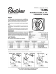
Model
Operating Instructions
300-206
Digital Heating/Cooling Thermostat
Your new Robertshaw thermostat has been designed to provide
accurate control and display of the room temperature. In addition, it
will also display all relevant information pertaining to your system.
The clearly marked buttons and informative display make it
extremely easy to understand and simple to use.
Please take a few moments to read the brief instructions and
familiarize yourself with the various functions in order to obtain
maximum benefit from this truly unique electronic control.
GENERAL INFORMATION
The thermostat normally displays room temperature, mode of
operation and whether cooling or heating is currently on. The
six buttons on the front of the unit allow complete control of
your equipment.
You may select different heating and cooling setpoints for the
system to maintain, e.g., 70° in heating and 75° in cooling.
Raising or lowering the setpoints in heating or cooling is as simple as pushing a button. In addition, you may choose to display
the temperature in °F or °C.
The thermostat also allows you to select continuous fan operation
(useful when using an air cleaner) or have the fan come on with
the equipment.
BUTTON FUNCTIONS
Outdoor
Press to display the outdoor temperature (optional)
Mode
Press to select cool only, heat only, auto (cool and
heat) or off
Fan
Press for continuous fan or auto fan
Day/Night
Press to alternate between day and night
temperature setpoints
USER CONTROLS
USER CONTROLS (cont)
LIMITED OVERRIDE
When the keyboard is locked (switch #2 LOCKED), the user may
override the temperature setpoint for 1 hour by pressing either the
or button. The range of temperature override is ± 3° F or ±
3° C from the programmed daytime setpoint.
OUTDOOR BUTTON
If your thermostat has been installed with an electronic outdoor
remote sensor (Uni-Line Part #529), you may view the outdoor
temperature simply by pressing the OUTDOOR button. Upon
releasing the button, the thermostat will once again display the
indoor temperature. If the option is not connected, the thermostat
will display ---.
DAY/NIGHT BUTTON
When the thermostat is installed initially, the display will show the
symbol for your day temperature. By pressing the DAY/NIGHT
button you may select an alternate setback or night temperature
(the thermostat will remember this setpoint). Simply press the
DAY/NIGHT button to alternate between temperature settings.
CELSIUS / FAHRENHEIT
Simultaneously press and to switch between Celsius (C) and
Fahrenheit (F) temperature display.
REMOTE SENSOR (OPTION)
RS1 – RS2 – RS+V
The thermostat is designed to accept the electronic remote sensor (Uni-Line Part #528) which will allow you to locate your thermostat in an area away from view.
CLOCK TERMINALS (OPTION) CLK1 – CLK2
Your thermostat is equipped with remote clock terminals. By
connecting a remote clock timer, the thermostat can be alternated between the day and night (setback) temperature setpoints
automatically.
TEMPERATURE ACCURACY
MODE
Select the desired mode of operation by repeatedly pressing the
MODE button.
Full temperature accuracy will only be realized after the thermostat has been installed and powered for at least one (1) hour.
COOLING POWER FAILURES
Controls the cooling system only. Select the temperature you
want while in the cooling mode by pressing and holding the
or buttons. The word COOL and the temperature setting is
displayed for 5 seconds.
HEATING
Controls the heating system only. Select the temperature you
want while in the heating mode by pressing and holding the
or buttons. The word HEAT and the temperature setting is
displayed for 5 seconds.
FAN The fan will come on automatically when the system is operating.
To select continuous fan operation, press the FAN button and the
display will show . This is recommended for electronic air
cleaners and continuous ventilation requirements.
OFF
To turn off the heating or cooling system, press the MODE button
until the word OFF appears on the LCD. Avoid using the OFF
mode during extremely cold weather to prevent damage to the
equipment from freezing.
111-135B
Your thermostat employs the latest in solid state electronic
technology.
One of the unique features of your thermostat is that no battery is
required to maintain your selected setpoints in the event of a
power loss as the memory is unaffected by power failures of
any duration.
When power is restored, the thermostat will continue operating as
if the power had never been off.
INSTALLATION INSTRUCTIONS
CAUTION
THIS DEVICE SHOULD BE INSTALLED BY A
QUALIFIED TECHNICIAN WITH DUE REGARD
FOR SAFETY, AS IMPROPER INSTALLATION
COULD RESULT IN A HAZARDOUS CONDITION
LOCATION
To ensure proper operation, the thermostat should be mounted on
an inside wall in a frequently occupied area of the building. In
addition, its position must be at least 18" (46cm) from any outside
wall, and approximately 5' (1.5m) above the floor in a location
with freely circulating air of an average temperature. You should
avoid the following locations:
– behind doors or in corners where freely circulating air is
unavailable;
– where direct sunlight or radiant heat from appliances might
affect control operation;
– on an outside wall;
– adjacent to, or in line with, conditioned air discharge grilles,
stairwells, or outside doors;
– where its operation may be affected by steam or water pipes or
warm air stacks in an adjacent partition space, or by an area
behind the thermostat which is not climate controlled;
– where its operation will be affected by the supply air of an adjacent climate control HVAC device; and
– near sources of electrical interference such as arcing relay
contacts
REMOVING THE THERMOSTAT FROM THE SUBBASE
WIRING DIAGRAMS
SINGLE TRANSFORMER
Add jumper for
single transformer
RH
W
RC
Y
G
CLK1
CLK2
HEAT STAGE #1
Line
Voltage
W
COOL STAGE #1
FAN
Y
24 VAC
Transformer
G
TWO TRANSFORMERS
1. Insert a flat blade screwdriver or coin 1/8" into the
slot located in the bottom center of the thermostat
case and twist 1/4 turn. When you feel or hear a click,
grasp the case from the bottom two corners and separate from
the subbase. Some models require more force than others
when separating due to the number of terminals used.
2. Swing the thermostat out from the bottom.
3. Lift the thermostat up and off the subbase.
4. Place the rectangular opening in the subbase over the equipment control wires protruding from the wall and, using the subbase as a template, mark the location of the two mounting
holes (exact vertical mounting is necessary only for appearance).
5. Use the supplied anchors and screws for mounting on drywall
or plaster; drill two 3/16" (5mm) diameter holes at the marked
locations; use a hammer to tap the nylon anchors in flush to
the wall surface and fasten subbase using the supplied screws.
(Do not over-tighten!)
6. Connect the wires from your system to the thermostat terminals. Carefully dress the wires so that any excess is pushed
back into the wall cavity or junction box. Ensure that the wires
are flush to the plastic subbase. The access hole should be
sealed or stuffed to prevent drafts from the wall affecting the
thermostat.
7. Before the thermostat is reinstalled on the subbase, install the
optional clock/timer, indoor remote sensor and outdoor remote
sensor, if used. Refer to the installation instructions supplied
with each option. Also check the position of the DIP switches
on the back of the thermostat.
If the fault indicator is ON, the transformers are OUT OF PHASE.
Switch the secondary wires of one of the transformers (NOT
BOTH) and ensure the red light goes OFF.
Single RH/RC Wire
Separate RH and RC Wires
REPLACING THE THERMOSTAT ON SUBBASE
4 min. (on/off)
1
Unlocked
Electric
2
2 min. (on/off)
3
Locked
Gas
RS2
1. Position the thermostat on the
hinged tabs at the top of the
subbase.
2. Gently swing the thermostat down
and press on the bottom
center until it snaps into place.
RH
RS1
W
RS+V
RC
Y
G
CLK1
CLK2
300-206
THERMOSTAT COVER LOCK
You may lock the cover down to prevent unauthorized access to the
thermostat by adding the plastic
lock (included in the installation bag).
Insert the plastic lock piece into the
bottom of the mounted base. The
ends of the lock piece fit snugly
under the lock pins extending from
the bottom of the mounted base.
The tab in the middle of the lock
piece extends down from the base.
To release the locking mechanism,
press the lock piece up and into the
base while gently prying open.
TERMINAL DESIGNATIONS
RH .............24 VAC from heating equipment transformer
W................Energizes the heating equipment with a call for heating
RC .............24 VAC from cooling equipment transformer
Y.................Energizes the cooling equipment with a call for cooling
G................Energizes the fan circuit
CLK1 .........Independent remote clock/timer optional for
CLK2
alternate setpoints
RS2............Use to connect remote temperature sensor(s).
RS1
Refer to the instructions included
RS+V
with the sensors.
DIP SWITCH OPTIONS
THERMISTOR MOUNTING INSTRUCTIONS
When placing the front
cover on the thermostat ensure the thermistor is not bent or
misaligned.
Ensure that the thermistor does not touch
the thermostat case.
The thermistor should
be placed horizontal to
the wall. Ensure the
thermistor is not
pushed upward
into the case.
The thermistor
should be aligned
so it is visible
between the ribs
on the bottom of
the subbase.
Located on the back of the thermostat once the subbase is
removed.
Switch #1 – Allows for a 4-minute or 2-minute minimum on/off time.
Switch #2 – Allows for the keypad to be locked or unlocked.
Switch #3 – Allows for an immediate fan (electric heat) or a
natural delay for the fan (gas/oil heat).
SPECIFICATIONS
Rated Voltage
Rated A.C.
Current
Control
Range
(Outside rear view with
backplate closed)
Thermostat
Measurement Range
O.D.T. Displayed
Range
Control Accuracy
Minimum
Deadband
20-30 VAC, 24 nominal
0.08 Amps to 1.5 Amps continuous
per output with surges to 4 Amps max.
Heating: 38° to 88°F in 1° Steps
5° to 30°C in 1° Steps
Cooling: 60° to 108°F in 1° Steps
16° to 40°C in 1° Steps
28° to 124°F or 0° to 48°C
-50° to 124°F or -48° to 48°C
±0.5°C at 20°C, ±1°F at 68°F
(between heating and cooling)
2°F or 1°C