1
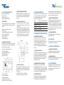
Technical
Specifications
External Beam Therapy System
Universal Care,
Economical Solutions
The Theratron® Phoenix™ is a highly practical
model of the Theratron® family of external beam
therapy systems (EBTS). Particularly appropriate for
treatment centres requiring extended hours of daily
operation and where budgetary considerations are
a major concern.
•National Council for Radiation Protection
(NCRP #102)
•International Commission for Radiation Units
(ICRU #18) External Beam Therapy System
Convenience and safety, combined with simplicity
of design, makes the Theratron® Phoenix™ easy to
use and easy to maintain. Routine maintenance can
be done effectively and quickly, keeping machine
down time to an absolute minimum.
Best® Theratronics is committed to ensuring the
highest achievable standards of safety, quality and
performance in the delivery of radiation therapy.
1.0 Basic Features
1.1 REGULATORY REQUIREMENTS
The Theratron® Phoenix™ is designed to comply
with the regulations and requirements of the
following agencies:
•Canadian Nuclear Safety Commission (CNSC)
Health Canada
•United States Nuclear Regulatory Commission
(USNRC)
•United States Food and Drug Administration
(USFDA)
413 March Road, Ottawa, ON K2K 0E4 Canada
phone 613 591 2100 fax 613 591 6627 www.theratronics.ca www.teambest.com
1
2.0 Head Assembly
The head of the Theratron® Phoenix™ is a cast
shell with lead and tungsten shielding. Maximum
capacity is 15,000 Curies equivalent to a unit output
of approximately 390 cGy/min. Air Kerma Rate at
isocentre. Sources are available in 1.5 and 2 cm
diameters.
2.1 SOURCE DRAWER MECHANISM
The pneumatically driven linear source drawer on
the Theratron® Phoenix™ moves the source between
the fully shielded and the fully exposed positions.
A carefully designed positioning mechanism
ensures accurate source positioning.
A large air reservoir tank is provided which allows
the source to cycle from the fully shielded position
to the fully exposed position and back at least three
(3) times in 30 seconds.
If the air pressure drops below a preset limit, the
source is automatically returned to, or retained in,
the fully shielded position.
In the event of a power failure, the source
automatically returns to its shielded position.
2.2 RADIATION SPECIFICATIONS
2.2.1 Head Leakage
The radiation leakage through the source housing
with the source in the fully shielded “Beam
Off ” position, measured at survey points, is in
accordance with NCRP #102.
Transmission through the head with the source in
the fully exposed position is less than 0.1% of the
primary beam.
2.2.2 Beamstopper Transmission
Transmission through the beamstopper is less than
0.3% of the primary beam for all field sizes.
2.3 HEAD ROTATION
The head may be swivelled manually ± 180° in either
direction from the isocentre. The head rotation
angle scale can be read from both sides of the unit.
2
2.4 COLLIMATOR
A manually adjustable divergent collimator
assembly defines the radiation beam. A fixed
tungsten definer and two pair of leaves allow
square and rectangular fields. The basic Source to
Diaphragm Distance (SDD) is 45 cm, which may be
increased to 55 cm with an optional trimmer set.
The “X” and “Y” settings are indicated on
mechanical scales located on the collimator.
2.7 RADIATION FIELD ACCURACY
2.7.1 Radiation Field Centre Coincidence
The maximum distance in any direction between
the centres of the radiation field and the light field,
measured at Source to Axis Distance (SAD) in a
plane perpendicular to the collimator rotation axis,
is:
Range
60 cm to 100 cm
Square fields up to 20 cm
± 2 mm
Increment
.5 cm
2.4.1 Field Size
Larger fields
± 1% of field size
Accuracy
± 1 mm
70 cm to 90 cm
± 2 mm
60 cm to 69 cm
90 cm to 100 cm
Minimum
Maximum
45 cm
5 cm x 5 cm
35 cm x 35 cm
55 cm
4 cm x 4 cm
34 cm x 34 cm
2.4.2 Accessory Mounting Pad
A magnetic pad on the collimator provides easy
mounting of the following:
•Mechanical distance indicator to indicate 80 cm
SSD and 100 cm SSD
•Mechanical backpointer
2.5 FIELD LIGHT
The field light system consists of the following:
•An external parabolic mirror projector assembly
designed to allow for quick and easy replacement
of the quartz halogen lamp.
•A secondary parabolic mirror is mounted on the
end of the source drawer. This refocuses and
directs the beam downward through the
collimator, producing a shadow of the cross wires
at the image plane aligned with the axes of the
field.
2.6 WEDGES
Wedges are available for use with the Theraton®
Phoenix™. The wedges vary in angle (15˚, 30˚, 45˚,
60˚), field size, and distance from source (45 cm or
55 cm). They are all made from lead-alloy except the
15°, which is made of brass (See Table 1).
2.7.2 Radiation Field Edge Coincidence
The maximum distance along the major axes
between the light edge and the radiation field edge,
measured at SAD for any particular field size, is:
1.5 cm source
Square fields up to 25 cm
± 2.5 mm
Larger fields
± 1% of field size
2 cm source
All field sizes
± 3 mm
2.8 COLLIMATOR ACCURACY
2.8.1 Collimator Centre Coincidence
The maximum distance in any direction between the
light field centre and the collimator rotation axis,
measured at Source Axis Distance (SAD) in a plane
perpendicular to the collimator rotation axis, is:
Gantry at 0° or 180°
Square fields up to 10 cm
± 1 mm
Larger fields
± 1% of field size
Gantry 90° or 270°
Square fields up to 20 cm
± 2 mm
Larger fields
± 1 % of field size
2.8.2 Isocentric Accuracy
The unit isocentre is defined as the point where the
collimator and gantry rotational axes intersect. This
point lies within a sphere of radius of 1 mm as the
gantry rotates through 360°.
2.9 OPTICAL DISTANCE INDICATOR
The Optical Distance Indicator (ODI) projects a
scale on the patient’s skin surface and provides
exceptional contrast against the skin surface. This
minimizes line diffusion on the skin as well as other
immobilization devices.
When the collimator rotates 360°, the maximum
variation of the ODI reading at SAD relative to the
reading at 0° is ± 2 mm.
3.0 Gantry
The gantry is capable of continuous rotation in both
clockwise and counter clockwise directions. Two
speeds are provided for gantry rotation to facilitate
treatment setup. Gantry speed for rotational and
arc treatment is adjustable up to 1 rpm.
The angle of the gantry is displayed on a circular
scale located at the centre of the gantry.
3.1 BEAMSTOPPER
The beamstopper is a lead filled steel assembly,
which acts as a beam absorber. The beamstopper
attenuates 99.7% of the primary beam and the
scatter radiation at an angle up to 30 degrees.
The optical backpointer is a standard feature on all
beamstopper units; it indicates the centre of the
beam at its exit point using a cross wire projection.
4.0 Covers
The covers are moulded from a flame-retardant
material designed to allow for easy removal and
servicing.
3
5.0 Controls and Indicators
The control system includes:
•Hand control(s)
•Remote control console
•Audible and visual indicators
5.1 HAND CONTROL
Ergonomically designed hand control rotates freely
around unit, allowing for easy access and ease of
operation.
The hand control features include:
•Gantry rotation
•Treatment Simulate push-button switch
•Motion “enabled” indicator
•Motion “drive” indicator
•Motion enable bar
•Emergency push-button
5.3 AUDIBLE AND VISUAL INDICATORS
Audible and visual indicators inside the treatment
room and at the control console reflect the position
of the source and unit status. These include the
following:
6.0 Treatment Table 27M
5.3.1 Inside the Treatment Room
• A head panel mounted on the front of the head
provides the visual indicators for “Beam On” and
“Beam Off.”
• A mechanical indicator is retracted in the head
when the source is in the fully shielded position and protrudes from the head when the source is in
or near the fully unshielded position. The motion of the mechanical indicator rod is independent from the operation of the radiation monitors.
Vertical 2 cm above - 37 cm below isocenter
Lateral
+/- 20 cm
Longitudinal
78 cm
Iso Rotation
+/- 110 deg
Top Rotation
+/- 180 deg
5.2 REMOTE CONTROL CONSOLE
The control console incorporates a Single Channel
Timer activated by the source positioning switches.
A dual timer option is available.
The control console features include:
•Power On-Off keyswitch
•Emergency Stop push-button
•“Beam On” indicator
•“Beam Off ” indicator
•“In Transit” indicator
•Timer reset push-button
•Treatment Mode select
•Treatment start push-button
•Treatment timer controls and display
4
Table vertical motion is motorized with max speed
of 0.6 cm/sec from hand control. All other motions
are manual with locking lever controls. Table
positions are indicated by scales.
7.0 Safety and Protective Interlocks
7.1 EMERGENCY STOP SWITCHES
The emergency stop switches, when activated,
disable the power from the unit and the table
motion drive circuits, causing the source to return
to or remain in the fully shielded position. The
emergency stop switches are located on the
control console, the unit main frame, and the hand
control(s).
7.2 “OFF SHIELD” INTERLOCK
The “Off Shield” interlock prevents the source from
being moved to, or remaining in, the fully exposed
position when the radiation beam is directed
through a part of the room that is not adequately
shielded. This interlock is set-up during the
installation of the unit.
5.3.2 At the Control Console
The source position is continuously monitored and
visually indicated on the control panel located on
the remote control console. The indicators reflect
the following:
•“Beam Off,” “In-Transit” or “Beam On”
•Inhibit, inhibit reset and power indicators
7.3 TREATMENT ROOM DOOR INTERLOCK
The treatment room door interlock inhibits
treatment when the treatment room door is open.
Should the treatment door open while a treatment
is in progress, the treatment will be paused and the
source returned to the fully shielded position.
disengaged while a moving beam treatment is in
progress, the treatment is paused and the source is
returned to the fully shielded position.
7.5 LOW AIR PRESSURE INTERLOCK
The low air pressure interlock prevents or pauses
the treatment when the air pressure in the
compressor air storage tank drops below a preset
limit. This ensures that the source cannot be moved
to, or remain in, the fully exposed position unless
there is sufficient air reserve to return the source to
the fully shielded position.
7.6 USER DOCUMENTATION
One User Manual and one Service Package are
included with the unit.
8.0 Accessories
There are a number of accessories available for the
Theratron® Phoenix™: (See Table 2).
9.0 Factory Installed Options
9.1 BACKLINE LASER INDICATION
Longitudinal laser line projection for patient
alignment. Use with pendulum units only.
9.2 PHOENIX DUAL TIMER
Factory fitted dual timer modification kit is available
which includes a wedge filter interlock.
10.0 Unit Installation
The Theratron® Phoenix™ must be installed by
qualified Best® Theratronics personnel, or by
personnel appointed by a Best® Theratronics
authorized agent.
7.4 HEADLOCK INTERLOCK
The headlock interlock prevents moving beam
treatments (rotation or arc) when the headlock
is disengaged. Should the headlock become
5
Installation includes:
1. Set-up of unit in a suitable location provided by the purchaser, installing all cables and connecting
the unit and control console to a suitable source
of electric power provided by the purchaser.
2. Loading of the source into the head of the unit.
3. A complete operational test of the unit and control equipment is performed on installation.
4. Training of facility personnel on equipment
controls and functionality.
10.1 INSTALLATION REQUIREMENTS
10.1.1 Electrical
Power requirements:
•115 V AC or 230 V AC ± 10% single phase, 50/60
Hz, 1.7 kVA.
•A circuit breaker rated at 20 amps is required for
line protection.
•All external connections to the unit are made to
the panel within the mainframe. Connections are
available for the following:
•Treatment room door interlock
•Remote “Beam On” and “Beam Off ” indicator
lights
•Remote emergency stop switch(es)
10.1.2 Environmental Requirements
•Ambient Operating Temperature Range:
10°C - 40°C
•Humidity Operating Range: 30% to 75% RH
10.1.3 Room Layout Requirements
Suggested room layout drawings are available on
request.
6
Table 1
11.0 General Information
11.1 UNIT DIMENSIONS
Standard Wedges
45 cm SDD
Weight (includes table)
4,707 kg
(10,375 lb.)
Wedge Angle
30 degrees
45 degrees
60 degrees
Maximum unit height
(above finished floor)
235 cm
(93 in.)
6W cm x 15L cm
6W cm x 15L cm
6W cm x 15L cm
8W cm x 15L cm
8W cm x 15L cm
8W cm x 15L cm
Maximum swing radius of
gantry (with head at 0˚)
109 cm
(43 in.)
10W cm x 15L cm
10W cm x 15L cm
10W cm x 15L cm
Part Number
G85-151
G85-152
G85-153
Isocentric height from
finished floor
116 cm
(45 in.)
55 cm SDD
Wedge Angle
30 degrees
45 degrees
60 degrees
6W cm x 15L cm
6W cm x 15L cm
6W cm x 15L cm
11.2 PROJECTED FLOOR AREA
3.19 m2 (34 sq. ft.) based on frame dimensions
127 cm x 251 cm (50 in. x 99 in.)
8W cm x 15L cm
8W cm x 15L cm
8W cm x 15L cm
10W cm x 15L cm
10W cm x 15L cm
10W cm x 15L cm
Part Number
G85-174
G85-175
G85-176
11.3 FLOOR LOADING
Typically 1800 kg/m2 (360 lb./sq. ft.) including
table
Wedge Sets
45 cm SDD
55 cm SDD
Wedge Angle
30/45/60 degrees
30/45/60 degrees
10W cm x 15L cm
Part Number
G85-154
10W cm x 15L cm
G85-155
Large Field Wedge
45 cm SDD
Wedge Angle
15 degrees
30 degrees
45 degrees
15W cm x 20L cm
15W cm x 20L cm
15W cm x 20L cm
Part Number
G85-282E
G85-151E
G85-152E
7
Table 2
Notes
Accessories*
Block Tray Rails
Short
For 5 cm blocks
G85-169A
Medium
For 7.6 cm Blocks/5 cm Blocks with Wedges
G85-169B
Long For 7.6 cm Blocks with Wedges
G85-169C
Beam Shielding
Beam Shaping Kit
21 pre-shaped 5 cm blocks
G85-097
Solid Tray
Acrylic
G85-150B
Slotted Tray
Acrylic
G85-150A
Breast Treatment Half Beam block
G85-207
Distance Indicators
Distance Indicator
Mechanical
G95-078A
Back Pointer
Mechanical
G85-022
Wedge Storage
Wedge Storage tray
9 positions
G85-178
Lasers
Positioning Diode Laser
2 Cross / 1 Sagittal
G85-238C
Positioning Diode Laser
3 Cross / 1 Sagittal
G85-238H
Monitors and Alarms
Room Radiation Monitor
G85-135A
Room Radiation Alarm
G85-135B
110V Battery Back Up
Charger
G85-135C
220V Battery Backup Converter
Must be used with 110V battery back up
G85-135D
Closed Circuit TV and intercom
CCTV System
110V
G85-306
CCTV System
220V
G85-306A
Intercom System
110V
G85-307
Intercom System
220V
G85-307A
Dosimetry
Electrometer and Farmer
ionization chamber
12 m cable, digital display
G93-353
Beam Data
80 cm Printed Depth Doses and
Profiles and Isodose curves
* Dependent on supplier availability
8
G85-011
9
Notes
10
Notes
11
413 March Road Ottawa, ON K2K OE4 Canada
Tel: 613 591 2100 1 866 792 8598
Fax: 613 591 6627 www.theratronics.ca
7643 Fullerton Road Springfield,VA 22153 USA
Tel: 703 451 2378 1 800 336 4970
Fax: 703 451 5228 www.teambest.com
BT/MTS 8012 (1)
© 2008 All Rights Reserved. Best Theratronics Theratron, Equinox, Phoenix and Avanza are registered trademarks of Best Theratronics Ltd.
© 2008 Best Theratronics. The specifications contained in this brochure are subject to change.
12


![Independence IDX 4000 IG User Manual [excerpts].](http://vs1.manualzilla.com/store/data/005651088_1-0e858df88d62387a8afea47c031c0cce-150x150.png)