1
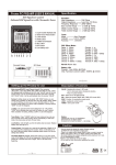
Sound for Generations
ROBERTS
RP28
3 Band Preset Portable Radio
Please read this manual before use
Controls (top panel)
1
2
3
4
9
8
1. ON/OFF button
2. AFC button
5. Telescopic aerial
6. Tuning tool
3. Preset buttons
4. Headphone socket
7. Volume control
8. Tone control
9. Tuning presets
5
7
6
Controls (LH end)
DC 9V
PIN -ve
PU9-B
10
INPUT 240V
50Hz
OUTPUT 9V
300mA
+
10.DC Socket
-
General
Tuning in the preset controls
Do not allow this unit to be exposed to water, steam or sand. Do not leave
the unit where excessive heat could cause damage such as in a parked car
where the heat from the sun can build up even though the outside
temperature may not seem too high. It is recommended that the FM band
be used were ever possible as better results in terms of quality and freedom
from interference will usually be obtained than on the MW or LW bands.
The 6 preset knobs (9) are numbered FM 1-4; MW and LW to correspond
with the preset buttons on the top panel. Remove the tuning tool (6) from
the space alongside the volume control. It may be necessary to tip the
receiver forward to remove the tuning tool.
Mains adaptor
Plug the adaptor into a 13A mains outlet. Plug the lead from the adaptor into
the DC socket (10). The battery will be automatically disconnected.
The mains adaptor should be disconnected from the mains supply when not
in use.
Batteries
Remove the battery cover on the base by releasing the catches and lifting
the cover up and out. Insert six IEC R14 (C size) cells into the compartment
Replace the battery cover.
Reduced power, distortion, and a ‘stuttering’ sound are all signs that the
batteries may need replacing.
If the radio is not to be used for any extended period of time it is
recommended that the batteries are removed from the radio.
We would recommend for economy, that the RP28 is used via the
Mains adaptor whenever possible with battery operation for occasional or stand-by use only.
Aerials
On FM fully extend the telescopic aerial (5), angle and rotate for best
reception.
On MW and LW stations are received on the built in ferrite rod aerial, rotate
the entire radio to the position giving best reception.
The telescopic aerial is inoperative on MW and LW.
Lift the preset control cover by means of the 2 lugs on the front corners.
Turn on the receiver by pressing the ON/OFF button (1)
To set up the 4 FM presets, fully extend the telescopic aerial (5) and, if the
AFC (2) button is depressed, press it to release it to the OFF (up) position.
Press one of the FM push-buttons (FM 1-4) and turn the volume control until
sound is audible. Engage the tuning tool into corresponding preset knob,
tune in the desired FM station. Lowest frequencies are at the anti-clockwise
end of rotation and highest at the clockwise end. The other 3 FM presets
may be set up in the same way. The AFC button (2) should now be
depressed. This will turn on the Automatic Frequency Control (AFC)
circuit which holds the stations firmly in tune. To set up the MW and LW
presets, follow the above procedure using the MW and LW buttons and
knobs. There is no need to extend the telescopic aerial or release the AFC
button as these are not operational on MW or LW. In some cases the tuning
point may be quite critical and care may be needed in setting the control
to the correct tuning position. The 6 presets will now be set to the required
stations but any of them may be altered at any time without affecting the
others. Replace the preset cover.
Using the radio once the presets have been set up
Turn on the receiver by pressing the ON/OFF button (1). Press the button
for the preset station you wish to receive. If this is a FM station, extend the
telescopic aerial .If the station is rather weak it may be necessary to angle
and rotate the aerial for optimum reception. If a MW or LW station is
selected, the radio itself should be turned for best reception. Adjust the
volume and tone controls for the desired level and tone of sound. To
change stations, press one of the other preset push-buttons. Switch the
RP28 off by pressing the ON/OFF button (1) to release it.
Headphones
Circuit Features
A 3.5mm socket (4) is provided for use with either headphones or an
earpiece. Inserting a plug into this socket automatically mutes the internal
loudspeaker.
4 ICs, 4 Transistors, 17 diodes.
Specifications
Loudspeaker
100mm 8ohms
Output Power
1watt into 8ohms
Headphone socket
3.5mm dia
Aerial System FM
Telescopic aerial
Power Requirements 9.0V
Batteries
6 x IEC R14 (C size)
Battery Life
Approx. 60hrs of listening for 4 hours a day at
normal volume using alkaline cells.
Frequency Coverage
FM
MW
Built-in Ferrite aerial
LW
Built-in Ferrite aerial
87.5-108MHz
MW
522- 1620kHz
LW
150- 281kHz
The Company reserves the right to amend the specification without notice.
Guarantee
This instrument is guaranteed for twelve months from the date of delivery to the original owner against failure due to faulty workmanship or component
breakdown, subject to the procedure stated below. Should any component or part fail during this guarantee period it will be repaired or replaced free of
charge.
The guarantee does not cover:
1. Damage resulting from incorrect use.
2. Consequential damage.
3. Receivers with removed or defaced serial numbers.
N.B. Damaged or broken telescopic aerials will not be replaced under guarantee.
Procedure:
Any claim under this guarantee should be made through the dealer from whom the instrument was purchased It is likely that your Roberts dealer will be
able to attend to any defect quickly and efficiently, but should it be necessary the dealer will return the instrument to the company’s service department
for attention. In the event that it is not possible to return the instrument to the Roberts dealer from whom it was purchased, please contact Roberts Radio
service department at the address shown on the back page of this manual before taking further action.
These statements do not affect the statutory rights of a consumer.
ROBERTS RADIO TECHNICAL SERVICES DEPARTMENT
97-99 Worton Road
Isleworth Middlesex
TW7 6EG
Technical Helpline:-020 8758 0338
Issue 4