1
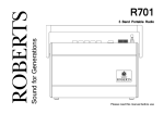
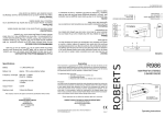
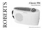
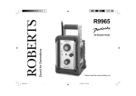
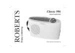
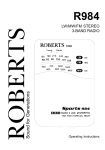
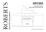
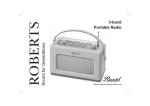
Sound for Generations
ROBERTS
R9903
3 Band Portable Radio
Sca le
LW
Pow er
0
MW
1
FM
2
160 0
108
2 80
140 0
3
2 60
4
120 0
106
5
2 20
10 0 0
104
8 00
100
8
6 00
92
7
18 0
70 0
96
6
2 00
16 0
15 0
9
10
5 30
Tuning
88
kH z
kH z
M Hz
R 9903
3 Band Portable Radio
Please read this manual before use
Controls
1
2
(Top)
LW MW FM
3
Scale
LW
(Front)
Power
0
MW
1
FM
2
160 0
108
2 80
140 0
3
2 60
4
120 0
106
104
4
5
2 20
10 0 0
8 00
100
8
6 00
92
7
18 0
70 0
96
6
2 00
16 0
15 0
9
10
5 30
Tuning
88
kH z
kH z
MHz
R 9903
3 Band Portable Radio
1. Telescopic Aerial
2. Waveband switch
3. Power LED
4. Tuning control
1
Controls
(Left side)
(Right side)
DC 6v
+
+
5
7
Vo lu m e
6
7
8
5. DC input socket
6. Headphone socket
7. Volume control
8. Battery compartment
If you need any further advice, please call our Technical Helpline on :0181 758 0338 (Mon-Fri)
2
Battery operation
1. Remove the Battery cover on the rear of the unit by pushing the catch
in the direction of the arrow.
2. Insert four LR6 (AA size) batteries into the spaces in the compartment.
Take care to ensure all batteries are inserted with the correct polarity
as shown inside the battery compartment. Replace the battery cover.
3. Reduced power, distortion, and a ‘stuttering’ sound are all signs that
the batteries may need replacing.
4. If the radio is not to be used for any extended period of time it is
recommended that the batteries are removed from the radio.
Operation via an AC adaptor (not included)
The AC adaptor for use with the R9903 should provide 6 volts DC output at
300mA centre pin negative (Roberts type PU6-B).
Sca le
LW
1. Place your radio on a flat surface.
Po wer
0
MW
1
FM
2
16 00
2 80
140 0
108
3
2 60
4
12 00
106
104
2. Plug the adaptor lead into the DC input socket located on the left hand
side end of your radio ensuring that the plug is pushed fully into the
socket. The batteries will be automatically disconnected
ROBERTS
PU6-B
9
10
5 30
Tuning
k Hz
k Hz
ON
3
160
150
88
3. Plug the adaptor into a wall socket and switch on.
8
6 00
92
7
180
70 0
96
6
2 00
8 00
100
5
2 20
100 0
M Hz
R 9 9 03
3 Ba n d Po rtab le Rad io
Operating your radio
1. Turn on your radio by rotating the Volume control clockwise until a
click is heard. The Power LED will light up
2. Set the Waveband selector to the required waveband.
3. Adjust the Volume control until a hissing sound is heard.
Volume
4. Rotate the Tuning knob to select the desired station. On MW and LW
the Tuning scale is marked in kilohertz (kHz). On FM the Tuning
scale is marked in Megahertz (MHz)
5. For MW and LW reception rotate your radio to the position giving best
reception.
LW
6. For FM reception fully extend the Telescopic aerial and then angle and
rotate for best reception. A knuckle joint at the base of the aerial allows
this movement and an angle of 45 degrees will usually be satisfactory.
MW
FM
6. Adjust the Volume control to the required sound level.
S ca le
LW
7. To turn off your radio rotate the Volume control fully anticlockwise
until a click is heard.
Power
0
MW
1
FM
2
1600
28 0
1400
108
3
26 0
4
12 00
106
100 0
104
Note : The telescopic aerial is inoperative on MW and LW.
700
96
6
20 0
80 0
100
5
22 0
8
60 0
92
7
180
160
150
9
10
53 0
Tu n in g
88
kH z
kH z
MH z
R 9 903
3 Band Portable Radio
If you need any further advice, please call our Technical Helpline on :0181 758 0338 (Mon-Fri)
4
Headphones
1. A Headphone Socket (3.5mm) located on the right hand end of your
radio is provided for use with either headphones or an earpiece.
Inserting the headphone plug automatically mutes the internal loudspeaker.
Vo lu m e
General
Do not allow this unit to be exposed to water, steam or sand. Do not leave
your radio where excessive heat could cause damage such as in a parked
car where the heat from the sun can build up even though the outside
temperature may not seem too high. It is recommended that the FM band
be used where ever possible as better results in terms of quality and
freedom from interference will usually be obtained than on the MW or LW
bands.
5
Specifications
Circuit Features
Power Requirements
Batteries
4 x LR6 (AA size)
External
DC 6 Volts
Loudspeaker
77mm
Output Power
400 mW into 8ohms
Headphone socket
3.5mm dia
Aerial System FM
Telescopic aerial
@ 300mA
centre pin negative (-).
Battery Life
Approx. 80hrs of listening for 4 hours a day at
normal volume using alkaline cells.
MW
Built-in Ferrite aerial
LW
Built-in Ferrite aerial
Frequency Coverage
FM
87.5-108MHz
MW
522- 1620kHz
LW
144- 281kHz
ROBERTS RADIO LIMITED
PO BOX 130
MEXBOROUGH
SOUTH YORKSHIRE
S64 8YT
The Company reserves the right to amend the specification without notice.
If you need any further advice, please call our Technical Helpline on :0181 758 0338 (Mon-Fri)
6
Guarantee
This instrument is guaranteed for twelve months from the date of delivery to the original owner against failure due to faulty workmanship or component
breakdown, subject to the procedure stated below. Should any component or part fail during this guarantee period it will be repaired or replaced free of
charge.
The guarantee does not cover:
1. Damage resulting from incorrect use.
2. Consequential damage.
3. Receivers with removed or defaced serial numbers.
N.B. Damaged or broken telescopic aerials will not be replaced under guarantee.
Procedure:
Any claim under this guarantee should be made through the dealer from whom the instrument was purchased. It is likely that your Roberts' dealer will
be able to attend to any defect quickly and efficiently, but should it be necessary the dealer will return the instrument to the company’s service department
for attention. In the event that it is not possible to return the instrument to the Roberts' dealer from whom it was purchased, please contact Roberts Radio
Technical Services department at the address shown below before taking further action.
These statements do not affect the statutory rights of a consumer.
ROBERTS RADIO TECHNICAL SERVICES DEPARTMENT
97-99 Worton Road
Isleworth Middlesex
TW7 6EG
Technical Helpline:- 0181 758 0338 (Mon-Fri)
Issue 1