1
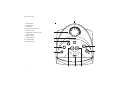
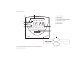
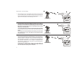
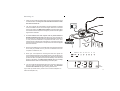
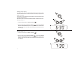
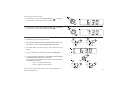
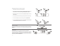
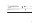
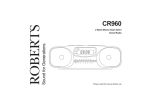
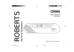
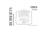
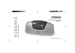
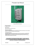
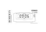
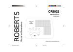
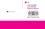
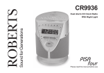
Sound for Generations
ROBERTS
CR9919
time cube clock radio
with atomic clock accuracy
Weekend
Cancel
MSF Signal
Auto
Dimmer
Sun
Mon
Tue
Wed
Thu
Fri
Sat
1
2
3
4
5
6
7
1
Auto
Summer
2
Radio 4
Radio 3
ILR
Radio 2 Local Radio 1
FM
MW
88
92
540 600
96 100
ILR
ILR
Local
104 106
700 800 1000 1300
108
MHz
1600 kHz
CR 9919
Please read this manual before use
Controls (top)
6
1. On/Off button
2. Sleep button
3. Time button
4. Week end cancel button
5. Volume control
6. Headphone socket (on rear)
5
Volume
7. Alarm 2 button
8. Alarm 1 button
9. Forward button
10. Snooze button
11. Reverse button
4
Weekend
Cancel
3
Time
7
2
2
Sleep
Reverse
1
8
Forward
Date
1
On/Off
Snooze
11
1
10
9
Controls (front)
15
12. Alarm 2 indicator
13. Auto dimmer
Weekend
Cancel
MSF Signal
Sun
Mon
Tue
Wed
Thu
Fri
Sat
1
2
3
4
5
6
7
14. Alarm 1 indicator
15. MSF signal/Day of week indicators
16. Auto summer indicator
14
Auto
Dimmer
13
17. LED dial pointer
1
18. Time Capsule
Auto
Summer
2
16
12
Radio 4
Radio 3
ILR
Radio 2 Local Radio 1
FM
MW
88
92
540 600
96 100
ILR
ILR
Local
104 106
700 800 1000 1300
108
MHz
1600 kHz
17
CR 9919
18
Automatic Winter/Summer Time
If you need any further advice, please call our Technical Helpline on :020 8758 0338 (Mon-Fri)
2
Controls (left side)
1
Radio
19
Buzz
Off
2
Radio
Buzz
Off
19. Alarm 1 function switch
20. Alarm 2 function switch
3
20
Controls (right side)
21
22
MW
FM
Tun ing
21. Waveband switch
22. Tuning control
23. Battery compartment
(on underside)
If you need any further advice, please call our Technical Helpline on :020 8758 0338 (Mon-Fri)
23
4
Automatic clock setting
1. When switched on the Time Capsule will receive and synchronise
your clock radio to one of the most accurate clocks in the world. The
signal is received from the official UK standard frequency and time
signal transmitter (MSF) located at Rugby in the U.K.
Automatic Winter /Summer Time
Weekend
Cancel
Sun Mon
M SF Si gnal
Auto
Di mmer
1
2
Tue
Wed
Thu
Fri
Sat
3
4
5
6
7
1
Auto
Summer
2
R adio 4
R adio 3
ILR
R adio 2 Local R adio 1
FM
MW
ILR
ILR
Local
88
92 96 10 0 10 4 10 6
540 600
700 800 1000 1300
MHz
10 8
1600 kHz
CR 9919
2. At certain times of the year the MSF transmitter closes down for
maintenance during this time it will be necessary to set the clock
manually (see the sections headed Setting the Time and Date
Manually). Recorded information on transmitter status can be
obtained on 020 8943 6493.
Your clock radio will only need to be set manually if the transmitter
is closed down when your clock radio is first connected to the
mains.
At all other times if the transmitter closes down your clock radio
will continue to run on its own highly accurate internal quartz
crystal time base.
3. Your clock radio will automatically synchronise with the MSF time
signal when the transmitter is switched back on. The time setting or
synchronisation takes 2 to 3 minutes to complete if the reception of the
radio time signal is undisturbed. This process will take longer if the
time signal level is very weak (e.g. in locations that are a long distance
from the MSF transmitter) or if it is subject to interference from
thunderstorms, nearby TV sets, computers or household appliances
that are not suppressed, etc.
In the event of a mains power failure your clock radio will
automatically synchronise with the MSF time signal and reset
the clock when the mains power is restored.
5
Automatic Winter /Summer Time
Weekend
Cancel
Sun Mon
M SF Si gnal
Auto
Di mmer
1
2
Tue
Wed
Thu
Fri
Sat
3
4
5
6
7
1
Auto
Summer
2
R adio 4
R adio 3
ILR
R adio 2 Local R adio 1
CLOSED
FM
MW
ILR
ILR
Local
88
92 96 10 0 10 4 10 6
540 600
700 800 1000 1300
MHz
10 8
1600 kHz
CR 9919
Automatic Winter /Summer Time
Weekend
Cancel
M SF Si gnal
Auto
Di mmer
Sun Mon
1
2
Tue
Wed
Thu
Fri
Sat
3
4
5
6
7
1
Auto
Summer
2
R adio 4
R adio 3
ILR
R adio 2 Local R adio 1
FM
MW
ILR
ILR
Local
88
92 96 10 0 10 4 10 6
700 800 1000 1300
540 600
CR 9919
MHz
10 8
1600 kHz
Switching on
1. Place your clock radio on a flat surface. Plug the mains lead into a wall
socket and switch on. Note your clock radio will not switch on until
the clock has been set.
ON
2. The Time Capsule will automatically activate the Radio Controlled
clock and initiate a search for the time signal. When first connected
to the mains supply the MSF signal indicator shows the MSF signal
level. Rotate the Time Capsule or change its position until the highest
signal level is obtained.
3. In most locations the time capsule can be placed behind a
bedside cupboard out of sight. If necessary the Time Capsule can
be secured to the cupboard using the double sided tape provided. If
a more permanent installation is required the base of the Time
Capsule can be snapped open at the split line - the base can then be
secured using two small screws. The top section can then be snapped
back onto the base.
4. We recommended that your clock radio and Time Capsule are placed
as far away as possible from any sources of interference such as
computers or televisions, etc.
5. When your Time Capsule is receiving the radio time signal, the
seconds digits will appear in the display and the colon will flash once
every second in time with the radio time signal. When the time setting
process has been completed, the exact time and day of the week will
appear in the display. The MSF signal indicator becomes the Day
of week indicator after initial time setting has taken place.
6. Your clock radio will automatically switch from summer to winter time
and vice versa by following the radio time signal. The Automatic
summer time indicator will light up during summer time.
If you need any further advice, please call our Technical Helpline on :020 8758 0338 (Mon-Fri)
Weekend
Cancel
MSF Signal
Sun
Mon
Tue
Wed
Thu
Fri
Sat
1
2
3
4
5
6
7
Auto
Summer
6
Setting the time manually
(only necessary if the MSF signal is not available)
Time
1. To set the time, press and hold down the Time button and adjust
using the Forward button or Reverse button until the correct time
appears. The clock uses a 24 hour display.
2. After setting the time, your clock radio will continue to run on its own
internal quartz time base and will automatically synchronise itself with
the radio time signal commencing on the 54th minute of every hour.
Once synchronisation is achieved the time and date of the radio time
signal will be restored and displayed.
Reverse
Forward
Note: Pressing the forward or reverse buttons once will cause the
display to move by one digit . Press and hold down the forward or
reverse buttons to rapidly change the display backwards or forwards.
Setting the date manually
(only necessary if the MSF signal is not available)
1. To set the date, press and hold down the Date button and adjust
using the Forward button or Reverse button until the correct date
appears.
Setting the year manually
(only necessary if the MSF signal is not available)
1. To set the year, press the Date button once to display the date, within
3 seconds press and hold down the Date button and adjust the year
using the Forward button or Reverse button until the correct year
appears.
7
Date
Snooze
Reverse
Forward
Date
Snooze
Reverse
Forward
Listening to the Radio
1. Switch on the radio by pressing the On/Off button . The LED dial
pointer will light up indicating that the radio is switched on.
Note your clock radio will not switch on until the clock has been
set.
LW
150
FM
On/Off
170
540 600 700
MW
88
92
96
200 230 260 280
900
100
1200
104 106
1600
108
kHz
kHz
MHz
2. Select the required waveband using the Waveband selector switch.
MW
FM
3. Tune in to the desired station by rotating the Tuning control. The
station frequency is indicated by the LED dial pointer.
The Wire aerial located on the rear of your clock radio is for FM
reception. The wire should be fully extended and positioned for
optimum reception.
LW
For MW reception there is a built in ferrite aerial. Rotate your clock
radio to the position giving best reception.
FM
150
170
540 600 700
MW
88
92
96
200 230 260 280
900
100
1200
104 106
1600
108
kHz
kHz
MHz
Tuning
4. Adjust the volume by rotating the Volume control.
Volume
5. The radio can be switched off by pressing the On/Off button.
On/Off
If you need any further advice, please call our Technical Helpline on :020 8758 0338 (Mon-Fri)
8
Setting alarm times
Your alarm clock radio has two separate alarms which can be set to
activate at different times. The alarms can be set to wake you by either the
buzzer or the radio.
In the event of a power failure the backup battery will ensure that the alarm
sounds at the preset time.
1
Note alarm times cannot be adjusted until the clock has been set.
Setting alarm 1
1. Press and hold down the Alarm 1 button (
1).
Reverse
Forward
2. Whilst holding down the Alarm 1 button (
1) press the Forward
button or Reverse button to set the required alarm time. Release the
buttons when the correct alarm time is reached. The clock uses a 24
hour display.
Setting alarm 2
1. Press and hold down the Alarm 2 button (
2)
2. Whilst holding down the Alarm 2 button (
2 ) press the Forward
button or Reverse button to set the required alarm time. Release the
buttons when the correct alarm time is reached. The clock uses a 24
hour display .
2
Reverse
9
Forward
Checking the Alarm Times
1. To check alarm 1 time, press the Alarm 1 button (
1) the display
will show alarm 1 time whilst the button is held down.
1
2. To check alarm 2 time, press the Alarm 2 button (
2 ) the display
will show alarm 2 time whilst the button is held down.
2
Setting the alarms to wake to buzzer
2
1
1. Set the alarm time as previously described.
2. Set the Alarm 1 function switch or Alarm 2 function switch to the
'Buzz' position. The corresponding Alarm indicators will light.
3. The buzzer alarm will sound every day at the preset time for 60
minutes.
Radio
Radio
Buzz
Buzz
Off
Off
1
2
4. To turn off the alarm until the next day press the On/Off button.
5.
To turn off the alarms permanently set the Alarm 1 function switch
or Alarm 2 function switch to the 'Off' position.
To make a distinction between alarm 1 and alarm 2 the alarm signals
have a different sound pitch:
Alarm 1 = lower pitch alarm signal
Alarm 2 = higher pitch alarm signal
If you need any further advice, please call our Technical Helpline on :020 8758 0338 (Mon-Fri)
1
On/Off
2
Radio
Radio
Buzz
Buzz
Off
Off
10
Setting the alarms to wake to radio
2
1
1. Set the alarm time as previously described.
2. Set the Alarm 1 function switch or Alarm 2 function switch to the
'Radio' position. The corresponding Alarm indicators will light.
3. Ensure that a station is tuned in and the Volume control is set to the
required level.
Radio
Radio
Buzz
Buzz
Off
Off
1
2
4. The radio alarm will sound every day at the preset time for 60 minutes.
5. To turn off the alarm until the next day press the On/Off button.
6. To turn off the alarms permanently set the Alarm 1 function switch
or Alarm 2 function switch to the 'Off' position.
2
1
Radio
Radio
Buzz
Buzz
Off
Off
Snooze control
Date
The radio or buzzer alarms can be silenced for 5 minutes by pressing the
Snooze button. This sequence can be repeated during the alarm cycle
(60 min).
Snooze
Sleep timer
The radio can be set to turn off after a preset time has elapsed.
Press and hold down the Sleep button until the desired time is reached
(maximum 90 minutes in 10 minute steps). The radio will switch off after the
sleep time has elapsed. To cancel the sleep function before the preset time
has expired, press the On/Off button.
11
Sleep
On/Off
Alarm weekend cancel
The alarms can be automatically cancelled at weekends.
1. To enable the weekend cancel function, press the Weekend cancel
button. The Weekend cancel indicator will light up in the display.
Weekend
Cancel
Weekend
Cancel
Sun
Mon
Tue
Wed
Thu
Fri
Sat
1
2
3
4
5
6
7
MSF Signal
2. Press the Weekend cancel button again to turn off the indicator and
disable this function.
Auto Dimmer
The Auto Dimmer located on the left side of the LED display will
automatically adjust the intensity of the clock display to suit room
brightness.
Auto
Dimmer
12
Specifications
Circuit Features
Power Requirements
Loudspeaker
Mains
AC 230 volts, 50Hz
Back-up Battery
IEC size 6LR61 (6F22, PP3)
Output power 350mW
Aerial System
Frequency Coverage
FM
87.5 - 108MHz
MW
525 - 1610kHz
75mm diameter 8 ohms
only
FM
Wire Aerial
MW
Built-in Ferrite aerial
ROBERTS RADIO LIMITED
PO BOX 130
MEXBOROUGH
SOUTH YORKSHIRE
S64 8YT
The company reserves the right to amend the specification without notice.
13
General
Fuse
Do not allow this unit to be exposed to water or steam. It is recommended
that the FM band be used wherever possible as better results in terms of
quality and freedom from interference will usually be obtained than on the
MW band.
This apparatus must be protected by a 3A fuse (BS1362) in a 13A plug
(BS1363). If another type of plug is used a 5A fuse should be fitted in the
plug, adaptor or distribution board.
Mains supply
Back-up Battery (not necessary for the unit to function)
The CR9919 will operate from a supply of AC 230volts, 50Hz
only.
For your convenience this product is supplied with a plug which is fitted
with a fuse of the appropriate rating. If the plug supplied is not suitable for
your socket outlet, it should be removed by unscrewing the plug top, the
terminal screws, and removing the cable.
The correct style of plug to suit your household together with a correctly
rated fuse should be fitted.
IF IN DOUBT - CONSULT A QUALIFIED ELECTRICIAN
IMPORTANT. DO NOT make any connection to the larger terminal which
or coloured
is marked with the letter E or by the safety earth symbol
Green or Green-and-yellow.
IF IN DOUBT - CONSULT A QUALIFIED ELECTRICIAN.
Slide the battery cover catch in the direction of the arrow. Remove the
battery cover. Fit a 9 volt IEC size 6LR61 (6F22, PP3) or equivalent battery
into the compartment. Replace the battery cover.
The time and alarm settings will be retained during a temporary failure of the
AC mains supply. The LED display will not be operational but the
Radio and buzzer alarms will continue to operate at their preset
times.
If your clock radio is not to be used for a prolonged period of time, remove
the battery to avoid damage by battery leakage.
(Underside)
The wires in the mains lead are coloured in accordance with the following
codes :BLUE - NEUTRAL
BROWN - LIVE
As these colours may not correspond with the coloured markings identifying
the terminals in your plug, proceed as follows:-
E (Earth)
Brown (Live)
3 amp
L
Blue (Neutral)
The wire coloured BLUE must be
connected to the terminal marked N
or coloured BLACK.
The wire coloured BROWN must be
connected to the terminal marked L
or coloured RED.
N
Mains Lead
If you need any further advice, please call our Technical Helpline on :020 8758 0338 (Mon-Fri)
14
Guarantee
This instrument is guaranteed for twelve months from the date of delivery to the original owner against failure due to faulty workmanship or component
breakdown, subject to the procedure stated below. Should any component or part fail during this guarantee period it will be repaired or replaced free of
charge.
The guarantee does not cover:
1. Damage resulting from incorrect use.
2. Consequential damage.
3. Receivers with removed or defaced serial numbers.
Procedure:
Any claim under this guarantee should be made through the dealer from whom the instrument was purchased. It is likely that your Roberts' dealer will
be able to attend to any defect quickly and efficiently, but should it be necessary the dealer will return the instrument to the company’s service department
for attention. In the event that it is not possible to return the instrument to the Roberts' dealer from whom it was purchased, please contact Roberts
Radio Technical Services Department at the address shown below before taking further action.
These statements do not affect the statutory rights of a consumer.
ROBERTS RADIO TECHNICAL SERVICES DEPARTMENT
97-99 Worton Road
Isleworth Middlesex
TW7 6EG
Technical Helpline:- 020 8758 0338 (Mon-Fri)
Issue 1