1
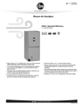
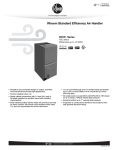
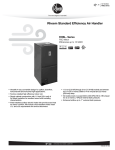
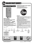
FORM NO. H11-528
Supersedes Form No. H11-526 Rev. 1
AIR HANDLERS
AIR HANDLERS
RHPN- SERIES – 18 SEER
featuring Earth-Friendly
R-410A Refrigerant
earth friendly refrigerant
Features
Includes an energy efficient GE® ECM® Motor, which in
most applications, enhances the SEER rating of the outdoor unit. It also slowly ramps its speed up for quiet operation and enhanced customer satisfaction.
■ Versatile 4-way convertible design for upflow, downflow,
horizontal left and horizontal right applications.
■ Nominal airflow up to 1.0" external static pressure.
■ Factory-installed high efficiency indoor coil.
■ Sturdy cabinet construction with 1.0 inch [25.4 mm] of
foil faced insulation for excellent sound and insulating
characteristics.
■ Field-installed auxiliary electric heater kits provide exact
heat for indoor comfort. Kits include circuit breakers which
meet U.L. and cUL requirements for service disconnect.
■ Dip switch settings for selectable, customized cooling airflow over a wide variety of applications.
■ On-demand dehumidification terminal that adjusts airflow
to help control humidity for unsurpassed comfort in cooling mode.
■ External filter required.
■
Engineering Features
RHPN- Series
Quiet, efficient ECM motor technology providing nominal airflow
up to 1.0 inch [25 kPa] of external static pressure.
■ Interface board with dip switches conveniently located in the
blower compartment allows for precise, field selectable airflow
to meet the requirements of particular applications.
■ Selectable continuous fan “on” options.
■ Compact unit design.
■ Attractive pre-painted cabinet exterior.
■ Rugged steel cabinet construction, designed for added
strength and versatility.
■ 1.0" foil faced insulation mechanically retained in blower
compartment.
■ Four leg rubber insulated motor mount.
■ Field-installed auxiliary heater kit includes circuit breakers that
meet UL and cUL requirements as a service disconnect switch.
■ Blower housing with integrated controls, motor and blower.
Slide out design for service and maintenance convenience.
■ Field convertible for vertical upflow, vertical downflow, horizontal left hand or right hand air supply.
■ Combustible floor base accessory available when required for
downflow installations on combustible floors.
■
Indoor coil design provides low air side pressure drop, high
performance and extremely compact size. All coils come with
PVC condensate elbow standard.
■ Coils are constructed of aluminum fins bonded to internally
grooved copper tubing.
■ Molded polymer corrosion resistant condensate drain pan is
provided on all indoor coils.
■ Supply duct flanges provided as standard on air handler
cabinet.
■ Provisions for field electrical connections available from either
side or top of the air handler cabinet.
■ Connection point for high voltage wiring is inside the air handler cabinet. Low voltage connection is made on the outside of
the air handler cabinet.
■ Concentric knockouts are provided for power connection to
cabinet. Installer may pull desired hole size up to 2 inches
[51 mm] for 11/2 inch [38 mm] conduit.
■ Internal checked TX valves are used on the Heat Pump indoor
coil for more quiet refrigerant metering.
■ Front refrigerant and drain connections.
■
[ ] Designates Metric Conversions
GENERAL TERMS OF LIMITED WARRANTY
Rheem will furnish a replacement for any part of this product
which fails in normal use and service within the applicable
periods stated, in accordance with the terms of the limited
warranty.
For Complete Details of the Limited Warranty, Including Applicable Terms
and Conditions, See Your Local Installer or Contact the Manufacturer for
a Copy.
2
Rheem Manufacturing Company
Rheem Prestige Series ® equipment features a 10-year
limited parts warranty.*
*This 10-year limited parts warranty is applicable only to single-phase
products installed in residential applications.
MODEL NUMBER DATA
R
H
P
N
— HM 24 21
J
A
Design Variation
A = 1st Design
Voltage
J = 208/240/1/60
Cabinet Size
21 = 21" [533.4 mm] (600-1200 CFM)
Capacity
24 = 18,000/24,000 BTUH
[5.27 to 7.03 kW]
HM = A/C or HP, Multi-Position
(Upflow & Horizontal Left is the factory configuration)
Refrigerant
N = R-410A
P = 18 SEER Premium Model
Classification
H = Air Handler
Rheem
Electrical Designation & Airflow Performance Information
1) Motor H.P. [W]
Model
Cabinet
Size
J = 208/240V, 1 PH, 60 Hz
2) Blower CFM [L/s]
1st/2nd Stage
Control
Designation
S = Circuit Breaker(s)
3) Blower Wheel
Dia./Width [mm]
4) Tonnage
1) 1/3 H.P. [249]
2421
21 = 21.0"
05
07
10
2) 600/800 CFM [283/378]
3) 10 x 8 [254 x 203]
4) 2 Ton
NOTES:
➀ Electrical Heat Designation: See electrical heat electrical data for actual heater kW represented by number above.
➁ Electric Heater: BTUH - (heater watts + motor watts) x 3.412 (see airflow table for motor watts).
➂ The air handlers are shipped from the factory with the proper indoor coil installed, and cannot be ordered without a coil.
➃ Electric heat elements are field-installed items.
➄ The air handlers do not have an internal filter rack. An external filter rack or other means of filtration is required.
[ ] Designates Metric Conversions
Rheem Manufacturing Company
3
Unit Dimensions
ELECTRICAL CONNECTIONS
MAY EXIT TOP OR EITHER SIDE
SUPPLY AIR
7/8
[22.2 mm],
HIGH VOLTAGE CONNECTION
13/32 [27.8 mm], 131/32 [50 mm] DIA.
KNOCKOUTS.
NOTE: 24 CLEARANCE REQUIRED IN FRONT OF
UNIT FOR FILTER AND COIL MAINTENANCE.
105/16
[262 mm]
W
A
Return Air Opening Dimensions
LOW VOLTAGE CONNECTION
5/8 [15.9 mm] AND 7/8 [22.2 mm] KNOCKOUT
Model
Cabinet Size
21
Return Air
Opening Width
(Inches)
193/8
Return Air Opening
Depth/Length
(Inches)
191/2
H
AUXILIARY DRAIN CONNECTION
3/4 [19.1 mm] FEMALE PIPE THREAD (NPT)
HORIZONTAL APPLICATION ONLY
PRIMARY DRAIN CONNECTION
3/4 [19.1 mm] FEMALE PIPE THREAD (NPT)
AUXILIARY DRAIN CONNECTION
3/4 [19.1 mm] FEMALE PIPE THREAD (NPT)
UPFLOW/DOWNFLOW APPLICATION ONLY
191/2 [495 mm]
RETURN AIR
OPENING
2111/16
[551 mm]
LIQUID LINE CONNECTION
COPPER (SWEAT)
VAPOR LINE CONNECTION
COPPER (SWEAT)
DOWNFLOW APPLICATION AND HORIZONTAL RIGHT
INDOOR COIL AND COIL DOOR ROTATES 180°
515/16
[151 mm]
HORIZONTAL ADAPTER KIT
41/8
1
[105 mm] 3 /16
[76 mm] 13/16 [48 mm] 11/8 [29 mm]
11/16
[27 mm]
13/8
[35 mm]
213/16
[71 mm]
VAPOR LINE
CONNECTION
AUXILIARY HORIZONTAL
DRAIN CONNECTION
PRIMARY DRAIN
CONNECTION
LIQUID LINE
CONNECTION
AUXILIARY UPFLOW/DOWNFLOW
DRAIN CONNECTION
UPFLOW UNIT SHOWN:
UNIT MAY BE INSTALLED UPFLOW,
DOWNFLOW, HORIZONTAL RIGHT
OR LEFT AIR SUPPLY.
VERTICAL DRAIN PAN
[ ] Designates Metric Conversions
( ) Designates Unit with Double Coil Cabinet
Unit Dimensions & Weights
Model
Unit
Width
“W” In. [mm]
Unit
Height
“H” In. [mm]
Supply
Duct
“A” In. [mm]
2421
21 [533]
421/2 [1080]
191/2 [495]
*Maximum dehumidification airflow.
4
51/4
[133 mm]
53/8
[136 mm]
Rheem Manufacturing Company
Nominal Coil Airflow [L/s]
1st Stage
2nd Stage
ODD*
Normal
ODD*
Normal
480 [227]
575 [271]
640 [302]
775 [366]
Unit Weight/Shipping Weight (Lbs.) [kg]
Unit With
Coil (Max. KW)
92/106 [42/48]
Airflow Directions
UPFLOW
HORIZONTAL LEFT
HAND AIRFLOW
DOWNFLOW
HORIZONTAL RIGHT
HAND AIRFLOW
Rheem Manufacturing Company
5
Airflow Performance
Airflow performance data is based on cooling performance
with a coil and no filter in place. Select performance table for
appropriate unit size, voltage and number of electric heaters to
be used. Make sure external static applied to unit allows operation within the minimum and maximum limits shown in table
below for both cooling and electric heat operation. For optimum
blower performance, operate the unit in the .1 [2.54 mm] to 1.00
inches [25.4 mm] W.C. external static range. Units with coils
should be applied with a minimum of .1 inch [2.54 mm] W.C.,
external static.
Airflow Performance and Electrical Data
Nominal
Cabinet
Cooling
Size
Capacity
Nominal
Airflow
Size
Thermostat CFM
Motor HP
Input
Y1
2 Ton
21
ECM
CFM [L/s] Air Delivery/RPM/Watts-230 Volts
Blower
External Static Pressure – Inches W.C. [kPa]
0.10
CFM
RPM
575
Watts
10 x 8
1/3
Y2
775
0.20
0.30
0.40
0.50
0.60
0.70
0.80
0.90
1.00
570 [269] 571 [269] 572 [270] 573 [270] 574 [271] 575 [271] 576 [272] 577 [272] 578 [273] 579 [273]
459
525
591
657
724
790
856
722
988
1054
37
54
71
88
105
123
140
157
174
191
CFM 772 [364] 778 [367] 783 [370] 788 [372] 794 [375] 799 [377] 805 [380] 810 [382] 816 [385] 821 [387]
486
550
615
679
744
809
873
938
1003
1061
RPM
56
80
104
128
151
175
199
228
247
271
Watts
IMPORTANT: Observe airflow operating limits. Do not operate above 1.0 in. W.C. system external static.
Blower Motor Electrical Data
Nominal Cooling
Capacity Tons
HP [W]
Voltage
Phase
Hertz
RPM
Circuit
Amps.
2
1/3 [249]
208/230
1
60
300-1100
1.7
Minimum
Circuit
Ampacity
4.0
Maximum
Circuit
Protector
15
Electric Heat Electrical Data
Installation of the UL Listed original equipment manufacturer provided heater kits
listed in the table below is recommended for all auxiliary heating requirements.
Air Handler
Cabinet Size/
Cooling
Capacity
Manufacturer
Model Number
Type Supply
Circuit
Voltage
PH/HZ
Heater kW
Heater AMPS
Motor
Ampacity
Maximum
Circuit
Protection
Minimum
Circuit
Ampacity
21" / 2 Ton
RXBH-24A05J
RXBH-24A07J
RXBH-24A10J
Single
Single
Single
208/240
208/240
208/240
1/60
1/60
1/60
3.6/4.8
5.4/7.2
7.2/9.6
17.3/20.0
26.0/30.0
34.6/40.0
1.7
1.7
1.7
25/30
35/40
50/60
24/28
35/40
46/53
• Supply circuit protective devices may be fuses or “HACR” type circuit breakers.
• Largest motor load is included in single circuit and multiple circuit 1.
• If non-standard fuse size is specified, use next size larger standard fuse size.
• J Voltage (230V) single phase air handler is designed to be used with single or three phase 230 volt electric heaters. In the case of connecting 3-phase power to the air handler terminal
block without the heater, bring only two leads to the terminal block cap, insulate and fully secure the third lead.
[ ] Designates Metric Conversions
Electrical Wiring
Power Wiring
• Field wiring must comply with the National Electrical Code
(C.E.C. in Canada) and any applicable local ordinance.
• Supply wiring must be 75°C minimum copper conductors only.
• See electrical data for product Ampacity rating and Circuit
Protector requirement.
6
Rheem Manufacturing Company
Grounding
• This product must be sufficiently grounded in accordance with
National Electrical Code (C.E.C. in Canada) and any applicable
local ordinance.
• A grounding lug is provided.
Accessories-Kits—Parts
• Combustible Floor Base RXHBModel Cabinet Size
21
Nominal Cooling
Capacity-Tons
2-3
Combustible Floor
Base Model Number
RXHB-21
Auxiliary Horizontal Overflow Pan
Accessory Model Number
RXBM-AC48
• Jumper Bar Kit 3 Ckt. to 1 Ckt. RXBJ-A31 is used to convert
single phase multiple three circuit units to a single supply
circuit. Kit includes cover and screw for line side terminals.
• Jumper Bar Kit 2 Ckt. to 1 Ckt. RXBJ-A21 is used to convert
single phase multiple two circuit units to a single supply circuit.
Kit includes cover and screw for line side terminals.
• Auxiliary Electric Heater Kits RXBHHeater Kits include circuit breakers which meet UL and cUL
requirements for service disconnect. See the Electric Heat
Electrical Data in this specification sheet for specific Heater Kit
Model numbers.
• Note: No jumper bar kit is available to convert three phase
multiple two circuit units to a single supply circuit.
[ ] Designates Metric Conversions
• External Filter Base RXHFModel
Cabinet Size
21
Filter Size
In. [mm]
20 x 20 [508 x 508]
Part
Number
RXHF-21
A
B
19.20
21.00
A
B
20.40
20.77
• External Filter Base RXHF-B
Model
Cabinet Size
21
Filter Size
In. [mm]
20 x 20 [508 x 508]
Part
Number*
RXHF-B21
*Accommodates 1" filter
RXHF-B
B
A
Rheem Manufacturing Company
7
Before proceeding with installation, refer
to installation instructions packaged
with each model, as well as complying
with all Federal, State, Provincial, and
Local codes, regulations, and practices.
RHEEM
AIR CONDITIONING
DIVISION
5600 Old Greenwood Road, Fort Smith, Arkansas 72908
“In keeping with its policy of continuous progress and product improvement, Rheem reserves the right to make changes without notice.”
PRINTED IN U.S.A.
5-07 DC
FORM NO. H11-528
Supersedes Form No. H11-526 Rev. 1