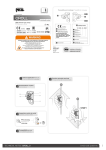
1
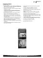
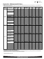
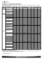
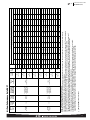
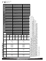
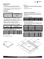
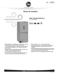
Air
Air Handlers
RH1T/RH2T Series
Rheem High Efficiency Air Handler
RH1T/RH2T- Series
Constant Torque Motor (ECM)
Efficiencies up to 16 SEER
• RH1T/RH2T feature a Constant Torque motor (ECM) which
provides enhanced SEER performance with most Rheem outdoor units.
• Versatile 4-way convertible design for upflow, downflow,
horizontal left and horizontal right applications.
• Factory-installed indoor coil.
• Sturdy cabinet construction with 1.0 inch [25.4 mm] of
foil faced insulation for excellent sound and insulating
characteristics.
• Field-installed auxiliary electric heater kits provide exact heat
for indoor comfort. Kits include circuit breakers which meet
U.L. and cUL requirements for service disconnect.
• 11/2 ton [5.3 kW] through 5 ton [17.6 kW] models are between
421/2 to 551/2 inches [1080 to 1410 mm] tall and 22 inches
[559 mm] deep.
• All models meet or exceed 330 to 400 CFM [156 to 189 L/s]
per ton at .3 inches [.7 kPa] of external static pressure.
• Enhanced airflow up to .7" external static pressure.
• Evaporator is constructed of aluminum fins bonded to internally grooved aluminum tubing.
FORM NO. H11-553 REV. 1
Air
Table of Contents
RH1T/RH2T Series
TABLE OF CONTENTS
Engineering Features ......................................................................................3
Model Number Identification ............................................................................4
Dimensional Data ........................................................................................5-6
Airflow Directional Data ..................................................................................7
Airflow Performance Data RH1T ..................................................................8-12
Electrical Data RH1T ................................................................................13-16
Airflow Performance Data RH2T ................................................................17-20
Electrical Data RH2T ................................................................................21-22
Electrical Wiring ............................................................................................23
Accessories ............................................................................................................23
Limited Warranty ..........................................................................................24
2
Air
Engineering Features
RH1T/RH2T Series
Engineering Features
RH1T/RH2T- Series
• The most compact unit design available, all standard heat air
handler models only 421/2 to 551/2 inches [1079 to 1409 mm] high.
• Attractive pre-painted cabinet exterior.
• Rugged wall steel cabinet construction, designed for added
strength and versatility.
• 1.0" foil faced insulation mechanically retained in blower
compartment for excellent thermal and sound performance.
• Four leg blower motor mount.
• Blower housing with controls, motor and blower. Slide out
design for service and maintenance convenience.
• Traditional open wire element design for heat applications.
• Field convertible for vertical downflow, horizontal left hand or
right hand air supply.
• 3 combustible floor base accessories fit all model sizes when
required for downflow installations on combustible floors.
• Indoor coil design provides low air side pressure drop, high
performance and extremely compact size.
• Expansion valve on indoor coil provides for operation with air
conditioning.
• Coils are constructed of aluminum fins bonded to internally
grooved aluminum tubing.
• Coils are tested at the factory with an extensive refrigerant
leak check.
• Coils have copper sweat refrigerant connections.
• Coils utilize chatleff metering device connections.
• Molded polymer corrosion resistant condensate drain pan is
provided on all indoor coils.
• Supply duct flanges provided as standard on air handler
cabinet.
• Provisions for field electrical, connections available from
either side or top of the air handler cabinet.
• Connection point for high voltage wiring is inside the air handler cabinet. Low voltage connection is made on the outside
of the air handler cabinet.
• Concentric knockouts are provided for power connection to
cabinet. Installer may pull desired hole size up to 2 inches
[51 mm] for 11/2 inch [38 mm] conduit.
• Front refrigerant and drain connections.
[ ] Designates Metric Conversions
3
R
Air
Model Number Identification
RH1T/RH2T Series
H
1
T
24
17
S
T
A
N
A
A
***
Option Code (see ADS-3803)
Blank = None
Minor Series
A = First
Voltage
A = 115/1/60
D = 480V/3/60
J = 208/240/1/60
Controls
C = Communicating
N = Non-Communicating
Major Series
A = First
Metering Device
T = TEV
E = EEV
P = Piston
Coil Efficiency
S = Standard
M = Medium
H = High
Width
17 = 17.5" [431.8 mm] (600-1200 CFM)
21 = 21" [533.4 mm] (800-1600 CFM)
24 = 24.5" [609.6 mm] (1400-1800 CFM)
Nominal Capacity
24 = 18,000 [5.27 kW]-24,000 [7.03 kW] BTU/H
36 = 30,000 [8.79 kW]-36,000 [10.55 kW] BTU/H
48 = 42,000 [12.31 kW]-48,000 [14.06 kW] BTU/H
60 = 60,000 [17.58 kW] BTU/H
Motor Type
T = Constant Torque (ECM)
Stages of Air Flow
1 = Single
2 = Two Stage
Product Category
H = Air Handler
Rheem
[ ] Designates Metric Conversions
Available Models at 115V A Voltage
RH1T2417STANAA
RH1T3617STANAA
RH1T3621MTANAA
RH1T4821STANAA
RH1T4824STANAA
RH1T6024STANAA
Available Models at 218V J Voltage
RH1T2417STANJA
RH1T3617STANJA
RH1T3621MTANJA
RH1T4821STANJA
RH1T4824STANJA
RH1T6024STANJA
RH2T2421MTANJA
RH2T3621MTANJA
RH2T4824MTANJA
RH2T6024STANJA
Available Models at D Voltage
RH1T6024STANDA
4
Dimensional Data
RH1T/RH2T Series
Air
Unit Dimensions
ELECTRICAL CONNECTIONS
MAY EXIT TOP OR EITHER SIDE
HIGH VOLTAGE CONNECTION 7/8 [22.2 mm],
13/32 [27.8 mm], 131/32 [50 mm] DIA. KNOCKOUTS.
SUPPLY AIR
NOTE: 24 CLEARANCE REQUIRED IN FRONT OF
UNIT FOR FILTER AND COIL MAINTENANCE.
105/16
[262 mm]
W
A
LOW VOLTAGE CONNECTION
5/8 [15.9 mm] AND 7/8 [22.2 mm] KNOCKOUT
Return Air Opening Dimensions
Model
Cabinet Size
Return Air
Opening Width
(Inches)
Return Air Opening
Depth/Length
(Inches)
17
21
24
157/8
193/8
227/8
193/4
193/4
193/4
H
AUXILIARY DRAIN CONNECTION
3/4 [19.1 mm] FEMALE PIPE THREAD (NPT)
HORIZONTAL APPLICATION ONLY
PRIMARY DRAIN CONNECTION
3/4 [19.1 mm] FEMALE PIPE THREAD (NPT)
AUXILIARY DRAIN CONNECTION
3/4 [19.1 mm] FEMALE PIPE THREAD (NPT)
UPFLOW/DOWNFLOW APPLICATION ONLY
191/2 [495 mm]
RETURN AIR
OPENING
2111/16
[551 mm]
LIQUID LINE CONNECTION
COPPER (SWEAT)
VAPOR LINE CONNECTION
COPPER (SWEAT)
UPFLOW UNIT SHOWN:
UNIT MAY BE INSTALLED UPFLOW, DOWNFLOW,
HORIZONTAL RIGHT OR LEFT AIR SUPPLY.
515/16
[151 mm]
HORIZONTAL ADAPTER KIT
41/8
1
[105 mm] 3 /16
[76 mm] 13/16 [48 mm] 11/8 [29 mm]
11/16
[27 mm]
13/8
[35 mm]
213/16
[71 mm]
VAPOR LINE
CONNECTION
51/4
[133 mm]
53/8
[136 mm]
AUXILIARY HORIZONTAL
DRAIN CONNECTION
UPFLOW UNIT SHOWN:
UNIT MAY BE INSTALLED UPFLOW,
DOWNFLOW, HORIZONTAL RIGHT
OR LEFT AIR SUPPLY.
PRIMARY DRAIN
CONNECTION
LIQUID LINE
CONNECTION
VERTICAL DRAIN PAN
[ ] Designates Metric Conversions
( ) Designates Unit with Double Coil Cabinet
AUXILIARY UPFLOW/DOWNFLOW
DRAIN CONNECTION
5
Air
Dimensional Data
RH1T/RH2T Series
Unit Dimensions & Weights
Model
Size
RH1T
Refrigerant Connections
Sweat (In.) [mm] ID
Liquid
Unit Dimensions
& Weights Vapor
Unit
Width
“W” In. [mm]
Unit
Height
“H” In. [mm]
Supply
Duct
“A” In. [mm]
Flow
Unit Weight/Shipping Weight
[ ] Air
Designates
Metric Conversions
CFM (Nom.) [L/s]
(Lbs.) [kg]
( ) Designates Unit with Double Coil Cabinet
Unit With
Lo
Hi
Coil (Max. KW)
2417ST
3/8
[9.53]
3/4
[19.05]
171/2 [445]
421/2 [1080]
161/2 [406]
600 [283]
800 [378]
3617ST
3/8
[9.53]
3/4
[19.05]
171/2
421/2
[1080]
161/2 [406]
1000 [472]
1200 [566]
96/110 [44/50]
3621MT
3/8
[9.53]
7/8
[22.23]
211/2 [533]
501/2 [1282]
191/2 [495]
1000 [472]
1200 [566]
126/142 [57/64]
4821ST
3/8
[9.53]
7/8
[22.23]
211/2 [533]
501/2 [1282]
191/2 [495]
1400 [661]
1600 [755]
128/144 [56/65]
4824ST
3/8
[9.53]
7/8
[22.23]
241/2 [622]
501/2 [1282]
231/2 [584]
1600 [755]
—
142/160 [64/72]
6024ST
3/8
[9.53]
7/8
[22.23]
241/2 [622]
551/2 [1410]
231/2 [584]
—
1800 [850]
159/176 [72/80]
Unit
Width
“W” In. [mm]
Unit
Height
“H” In. [mm]
Supply
Duct
“A” In. [mm]
Lo
[445]
92/105 [42/48]
*Maximum dehumidification airflow.
Unit Dimensions & Weights
Model
Size
RH2T
Refrigerant Connections
Sweat (In.) [mm] ID
Liquid
Vapor
Air Flow
CFM (Nom.) [L/s]
Unit Weight/Shipping Weight
(Lbs.) [kg]
Hi
Unit With
Coil (Max. KW)
2421MT
3/8
[9.53]
3/4
[19.05]
211/2 [533]
421/2 [1080]
191/2 [495]
525 [248]
700 [330]
111/126 [50/57]
3621MT
3/8
[9.53]
7/8
[22.23]
211/2
501/2
[1282]
191/2 [495]
800 [377]
1050 [495]
129/145 [59/66]
4824MT
3/8
[9.53]
7/8
[22.23]
241/2 [622]
551/2 [1410]
231/2 [584]
1050 [495]
1400 [660]
128/146 [58/66]
6024ST
3/8
[9.53]
7/8
[22.23]
241/2 [622]
551/2 [1410]
231/2 [584]
1200 [566]
1600 [755]
161/178 [73/81]
[ ] Designates Metric Conversions
6
[533]
Air
Airflow Directional Data
RH1T/RH2T Series
Airflow Directional Data
UPFLOW
HORIZONTAL LEFT
HAND AIRFLOW
DOWNFLOW
HORIZONTAL RIGHT
HAND AIRFLOW
7
Air
Airflow Performance Data
RH1T/RH2T Series
Airflow Performance
below for both cooling and electric heat operation. For optimum blower performance, operate the unit in the .3 [8 mm] to
.7 inches [18 mm] W.C. external static range. Units with coils
should be applied with a minimum of .1 inch [3 mm] W.C.
external static range.
Airflow performance data is based on cooling performance
with a coil and no filter in place. Select performance table for
appropriate unit size, voltage and number of electric heaters to
be used. Make sure external static applied to unit allows operation within the minimum and maximum limits shown in table
Airflow Operating Limits
Model Cabinet Width
Cooling BTUH x 1,000
Cooling Tons Nominal
17
17/21
21
24
-18
1.5
-24
2
-30
2.5
-36
3
-42
3.5
-48
4
-48
4
-60
5
Heat Pump or Air Conditioning
Maximum Heat/Cool CFM [L/s]
(37.5 CFM [18 L/s]/1,000 BTUH)
(450 CFM [212 L/s]/Ton Nominal)
675
[319]
900
[425]
1125
[531]
1350
[637]
1575
[743]
1800
[850]
1800
[850]
1930
[911]
Heat Pump or Air Conditioning
Nominal Heat/Cool CFM [L/s]
(33.3 CFM [16 L/s]/1,000 BTUH)
(400 CFM [189 L/s]/Ton Nominal)
600
[283]
800
[378]
1000
[472]
1200
[566]
1400
[661]
1600
[755]
1600
[755]
1800
[850]
Heat Pump or Air Conditioning
Minimum Heat/Cool CFM [L/s]
(30.0 CFM [14 L/s]/1,200 BTUH)
(360 CFM [170 L/s]/Ton Nominal)
540
[255]
720
[340]
900
[425]
1080
[510]
1260
[595]
1440
[680]
1440
[680]
1620
[765]
Maximum kW Electric Heating
& Minimum Electric Heat CFM [L/s]
13
487 [230]
13
617 [291]
18
814 [384]
18
1054 [497]
20
1171 [553]
25
1502 [709]
25
1502 [709]
30
1666 [786]
Maximum Electric Heat Rise °F [°C]
80 [26.7]
63 [17.2]
66 [18.9]
51 [10.6]
49 [9.4]
50 [10]
50 [10]
54 [12.2]
[ ] Designates Metric Conversions
8
Air
Airflow Performance Data
RH1T/RH2T Series
115V/208V/240V/460V Airflow Performance Data—RH1T (Constant Torque (ECM) Motor)
Model
No.
RH1T
Tonnage
Application
Motor
Speed
From
Factory
Manufacturer Blower Size/
Recommended
Motor
Motor
Air-Flow Range
HP [W]
Speed
(Min/Max) CFM # of Speed
2
2417ST
No Heat
1.5 Ton
5
683/485
[322/229 L/s]
10x8
1/3 HP [249]
5 Speed
3
2
2417ST
with 13 kW
Heater
1.5 Ton
5
683/485
[322/229 L/s]
10x8
1/3 HP [249]
5 Speed
3
4
2417ST
No Heat
2 Ton
5
858/697
[405/329 L/s]
10x8
1/3 HP [249]
5 Speed
5
4
2417ST
with 13 kW
Heater
2 Ton
5
683/485
[322/229 L/s]
10x8
1/3 HP [249]
5 Speed
5
X-13 CFM [L/s] Air Delivery/RPM/Watts—115/208/240 Volts
External Static Pressure—Inches W.C. [kPa]
0.1 [.02]
0.2 [.05]
0.3 [.07]
0.4 [.10]
0.5 [.12]
0.6 [.15]
0.7 [.17]
CFM
837 [395]
713 [366]
608 [287]
554 [261]
485 [229]
—
—
RPM
565
587
630
692
751
—
—
Watts
95
81
88
74
66
—
—
CFM
—
—
—
—
683 [322]
615 [290]
572 [270]
RPM
—
—
—
—
789
842
892
Watts
—
—
—
—
140
159
155
CFM
814 [384]
692 [326]
589 [278]
535 [252]
467 [220]
—
—
RPM
592
613
656
719
778
—
—
Watts
108
90
97
82
73
—
—
CFM
—
—
—
—
808 [381]
629 [297]
584 [276]
RPM
—
—
—
—
789
842
892
Watts
—
—
—
—
148
168
163
CFM
902 [426]
846 [399]
788 [372]
742 [350]
679 [320]
—
—
RPM
596
645
694
741
791
—
—
Watts
105
108
116
121
130
—
—
CFM
—
—
—
—
858 [276]
816 [385]
770 [363]
RPM
—
—
—
—
834
879
925
Watts
—
—
—
—
185
182
214
CFM
882 [416]
827 [390]
769 [363]
723 [341]
661 [312]
—
—
RPM
595
670
719
767
817
—
—
Watts
113
125
124
129
197
—
—
CFM
—
—
—
—
833 [393]
791 [373]
746 [352]
RPM
—
—
—
—
852
898
Watts
—
—
—
—
192
189
222
935 [441]
—
—
CFM 1093 [516] 1050 [496] 1017 [480] 977 [461]
2
3617ST
No Heater
2.5 Ton
5
935/1084 CFM
[441/512 L/s]
10x8
1/2 HP [373]
5 Speed
3
RPM
671
725
764
809
852
—
—
Watts
153
168
174
180
188
—
—
CFM
—
—
—
—
RPM
—
—
—
—
896
936
971
Watts
—
—
—
—
249
257
261
952 [449]
910 [429]
—
—
CFM 1068 [504] 1025 [484] 992 [468]
2
3617ST
with 18 kW
Heater
2.5 Ton
5
910/1059 CFM
[429/500 L/s]
10x8
1/2 HP [373]
5 Speed
3
4
3617ST
No Heater
3 Ton
5
1130/1275 CFM
[533/602 L/s]
10x8
1/2 HP [373]
5 Speed
5
4
3617ST
with 18 kW
Heater
3 Ton
5
1105/1250 CFM
[521/590 L/s]
10x8
1/2 HP [373]
5 Speed
5
1084 [512] 1040 [491] 1001 [472]
RPM
711
765
804
849
892
—
—
Watts
164
179
185
191
199
—
—
CFM
—
—
—
—
RPM
—
—
—
—
936
976
1011
Watts
—
—
—
—
260
268
272
CFM 1270 [599] 1237 [584] 1199 [566] 1165 [550] 1130 [533]
—
—
RPM
775
816
846
882
926
—
—
Watts
237
249
259
268
277
—
—
CFM
—
—
—
—
RPM
—
—
—
—
963
999
1029
Watts
—
—
—
—
338
348
363
CFM 1245 [588] 1212 [572] 1174 [554] 1140 [538] 1105 [521]
—
—
RPM
815
856
886
922
966
—
—
Watts
248
260
270
279
288
—
—
CFM
—
—
—
—
RPM
—
—
—
—
1003
1039
1069
Watts
—
—
—
—
349
359
374
1059 [500] 1015 [479] 976 [461]
1275 [602] 1244 [587] 1211 [571]
1250 [590] 1219 [575] 1186 [560]
[ ] Designates Metric Conversions
9
Air
Airflow Performance Data
RH1T/RH2T Series
115V/208V/240V/460V Airflow Performance Data—RH1T (Constant Torque (ECM) Motor) (con’t.)
Model
No.
RH1T
Tonnage
Application
Motor
Speed
From
Factory
Manufacturer Blower Size/
Recommended
Motor
Motor
Air-Flow Range
HP [W]
Speed
(Min/Max) CFM # of Speed
2
3621MT
No Heater
2.5 Ton
4
854/1103 CFM
[403/521 L/s]
10x10
3/4 HP [559]
5 Speed
3
PSC CFM [L/s] Air Delivery/RPM/Watts—115/208/240 Volts
External Static Pressure—Inches W.C. [kPa]
0.1 [.02]
0.2 [.05]
0.3 [.07]
0.4 [.10]
0.5 [.12]
0.6 [.15]
0.7 [.17]
CFM 1073 [506] 1016 [479] 963 [454]
906 [428]
854 [403]
—
—
—
RPM
637
692
746
801
847
—
Watts
130
142
153
165
176
—
—
CFM
—
—
—
—
1103
1059
1000
RPM
—
—
—
—
917
957
1001
Watts
—
—
—
—
262
271
285
936 [442]
880 [415]
828 [391]
—
—
—
CFM 1044 [493] 988 [466]
2
3621MT
with 18 kW
Heater
2.5 Ton
4
828/1016 CFM
[391/479 L/s]
10x10
3/4 HP [559]
5 Speed
3
4
3621MT
No Heater
3 Ton
4
1070/1288 CFM
[505/608 L/s]
10x10
3/4 HP [559]
5 Speed
5
4
3621MT
with 18 kW
Heater
3 Ton
4
1042/1257 CFM
[492/593 L/s]
10x10
3/4 HP [559]
5 Speed
5
RPM
678
734
791
844
883
—
Watts
141
155
158
171
182
—
—
CFM
—
—
—
—
1016
961
904
RPM
—
—
—
—
939
968
1015
Watts
—
—
—
—
233
243
265
CFM 1264 [597] 1223 [577] 1171 [553] 1112 [525] 1070 [505]
—
—
RPM
724
761
814
868
900
—
—
Watts
198
208
222
237
245
—
—
CFM
—
—
—
—
1288
1244
1200
RPM
—
—
—
—
974
1012
1044
Watts
—
—
—
—
345
362
371
CFM 1233 [582] 1193 [563] 1142 [539] 1084 [512] 1042 [492]
—
—
RPM
759
794
845
915
933
—
—
Watts
219
215
227
251
261
CFM
—
—
—
—
1257
1213
1169
RPM
—
—
—
—
1020
1023
1054
Watts
—
—
—
—
355
368
376
Notes: Constant Torque motor speed changes.
All Constant Torque motors have 5 speed tabs. Speed tab 1 is for continuous fan. Speed tab 2 (low static) and Speed tab 3 (high static) are for lower tonnage. Speed
tab 4 (low static) and Speed tab 5 (high static) are for higher tonnage.
Constant Torque air handlers are always shipped from factory at Speed tab 5, except for -4824, which is set at Speed tab 3. For instance, (-)H1T-HM2417JA is always
shipped at high static 2-ton airflow (Speed tab 5). To change to 1.5-ton airflow, move the blue wire to Speed tab 2 or 3 on the Constant Torque motor.
The low static Speed tab 2 (lower tonnage) and 4 (higher tonnage) are used for external static below 0.5" WC. The high static Speed tab 3 (lower tonnage) and 5
(higher tonnage) are used for external static exceeding 0.5" WC. Move the blue wire to the appropriate Speed tab as required by the application needs.
• The airflow for continuous fan (Speed tab 1) is always set at 50% of the Speed tab 4.
• The above airflow table lists the airflow information for air handlers without heater and air handler with maximum heater allowed for each model.
• The following formula can be used to calculate the approximate airflow, if a smaller (N kW) than the maximum heater kit is installed.
Approximate Airflow = Airflow without heater – (Airflow without heater – Airflow with maximum heater) x (N kW/maximum heater kW)
[ ] Designates Metric Conversions
10
Air
Airflow Performance Data
RH1T/RH2T Series
115V/208V/240V/460V Airflow Performance Data—RH1T (Constant Torque (ECM) Motor) (con’t.)
Model
No.
RH1T
Tonnage
Application
Motor
Speed
From
Factory
Manufacturer Blower Size/
Recommended
Motor
Motor
Air-Flow Range
HP [W]
Speed
(Min/Max) CFM # of Speed
2
4821ST
No Heater
3.5 Ton
5
1337/1447 CFM
[631/683 L/s]
10x10
3/4 HP [559]
5 Speed
3
2
4821ST
with 20 kW
Heater
3.5 Ton
5
1297/1333 CFM
[612/629 L/s]
10x10
3/4 HP [559]
5 Speed
3
4
4821ST
No Heater
4 Ton
5
1535/1654 CFM
[724/781 L/s]
10x10
3/4 HP [559]
5 Speed
5
4
4821ST
with 25 kW
Heater
4 Ton
5
1495/1614 CFM
[706/762 L/s]
10x10
3/4 HP [559]
2 Speed
5
2
4824ST
No Heater
4 Ton
3
1545/1732 CFM
[729/817 L/s]
11x11
3/4 HP [559]
5 Speed
3
2
4824ST
with 25 kW
Heater
4 Ton
3
1505/1692 CFM
[710/798 L/s]
11x11
3/4 HP [559]
5 Speed
3
2
6024ST
No Heater
5 Ton
4, 5
1517/1699 CFM
[715/800 L/s]
11x11
3/4 HP [559]
5 Speed
3
2
6024ST
with 30 kW
Heater
5 Ton
4, 5
1477/1655 CFM
[687/785 L/s]
11x11
3/4 HP [559]
5 Speed
3
PSC CFM [L/s] Air Delivery/RPM/Watts—115/208/240 Volts
External Static Pressure—Inches W.C. [kPa]
0.1 [.02]
0.2 [.05]
0.6 [.15]
0.7 [.17]
CFM 1473 [695] 1442 [681] 1401 [661] 1373 [648] 1337 [631]
0.3 [.07]
0.4 [.10]
0.5 [.12]
—
—
RPM
781
825
867
905
949
—
—
Watts
257
271
303
307
315
—
—
CFM
—
—
—
—
RPM
—
—
—
—
987
1034
1065
Watts
—
—
—
—
394
406
405
CFM 1433 [676] 1402 [662] 1361 [642] 1333 [629] 1297 [612]
—
—
RPM
831
875
919
954
989
—
—
Watts
277
295
313
319
325
—
—
CFM
—
—
—
—
RPM
—
—
—
—
1011
1046
1080
Watts
—
—
—
—
350
364
377
CFM 1665 [786] 1631 [770] 1601 [756] 1572 [742] 1535 [724]
—
—
RPM
853
893
934
968
1015
—
—
Watts
351
387
401
406
422
—
—
CFM
—
—
—
—
RPM
—
—
—
—
1036
1078
1095
Watts
—
—
—
—
500
513
523
CFM 1625 [767] 1591 [751] 1561 [737] 1532 [723] 1495 [706]
—
—
RPM
894
932
970
1020
1052
—
—
Watts
389
400
410
430
450
—
—
CFM
—
—
—
—
RPM
—
—
—
—
1085
1090
1105
Watts
—
—
—
—
514
520
530
CFM 1748 [825] 1669 [788] 1639 [773] 1599 [755] 1545 [729]
—
—
RPM
660
698
734
762
795
—
—
Watts
297
311
326
340
353
—
—
CFM
—
—
—
—
RPM
—
—
—
—
840
872
899
Watts
—
—
—
—
448
467
480
CFM 1708 [806] 1629 [769] 1599 [755] 1559 [736] 1505 [710]
—
—
RPM
680
736
760
790
820
—
—
Watts
305
330
341
350
361
—
—
CFM
—
—
—
—
RPM
—
—
—
—
865
890
1014
Watts
—
—
—
—
460
470
481
CFM 1705 [800] 1661 [703] 1632 [770] 1572 [741] 1517 [915]
—
—
RPM
663
701
741
782
819
—
—
Watts
292
309
321
343
357
—
—
CFM
—
—
—
—
RPM
—
—
—
—
857
895
920
Watts
—
—
—
—
447
466
473
CFM 1665 [995] 1621 [965] 1592 [751] 1532 [723] 1477 [697]
—
—
RPM
701
739
779
820
857
—
—
Watts
313
330
342
364
378
—
—
CFM
—
—
—
—
RPM
—
—
—
—
895
933
958
Watts
—
—
—
—
968
487
494
1447 [683] 1433 [676] 1402 [662]
1333 [629] 1300 [613] 1267 [598]
1654 [781] 1624 [766] 1563 [738]
1614 [762] 1584 [748] 1523 [719]
1732 [817] 1683 [794] 1630 [769]
1692 [798] 1643 [775] 1590 [750]
1699 [500] 1646 [776] 1601 [725]
1657 [787] 1606 [759] 1561 [735]
[ ] Designates Metric Conversions
11
Air
Airflow Performance Data
RH1T/RH2T Series
115V/208V/240V/460V Airflow Performance Data—RH1T (Constant Torque (ECM) Motor) (con’t.)
Model
No.
RH1T
Tonnage
Application
Motor
Speed
From
Factory
Manufacturer Blower Size/
Recommended
Motor
Motor
Air-Flow Range
HP [W]
Speed
(Min/Max) CFM # of Speed
4
6024ST
No Heater
5 Ton
5
1739/1905 CFM
[821/899 L/s]
11x11
3/4 HP [559]
5 Speed
5
4
6024ST
with 30 kW
Heater
5 Ton
5
1699/1865 CFM
[802/880 L/s]
11x11
3/4 HP [559]
5 Speed
5
X-13 CFM [L/s] Air Delivery/RPM/Watts—115/208/240 Volts
External Static Pressure—Inches W.C. [kPa]
0.1 [.02]
0.2 [.05]
0.6 [.15]
0.7 [.17]
CFM 1902 [898] 1862 [879] 1809 [854] 1781 [840] 1739 [821]
0.3 [.07]
0.4 [.10]
0.5 [.12]
—
—
RPM
712
749
787
815
856
—
—
Watts
389
409
419
432
459
—
—
CFM
—
—
—
—
RPM
—
—
—
—
894
924
950
Watts
—
—
—
—
565
570
592
CFM 1862 [879] 1822 [860] 1769 [835] 1741 [822] 1699 [802]
—
—
RPM
750
790
810
850
880
—
—
Watts
410
420
430
455
479
—
—
CFM
—
—
—
—
RPM
—
—
—
—
920
945
970
Watts
—
—
—
—
565
587
610
1905 [899] 1866 [881] 1832 [865]
1865 [880] 1826 [862] 1792 [846]
Notes: • All 208/240V PSC motors have voltage taps for 208 and 240 volts.
• All 208/240V PSC motors are shipped on high speed and 240 volts.
• If the application external static is less than 0.5" WC, adjust the motor speed to the low static speed as described below:
• Unplug the black motor wire off the relay on the control board and plug in the red motor wire.
• Replace the cap on the black motor wire.
• Voltage change (208/240V motors):
• Move the orange lead to transformer 208V tap from 240V tap. Replace the wire cap on 240V tap.
• Unplug the purple motor wire off the transformer and plug in the yellow motor wire.
• Replace the cap on the purple motor wire.
• The above airflow table lists the airflow information for air handlers without heater and air handler with maximum heater allowed for each model.
• The following formula can be used to calculate the approximate airflow, if a smaller (N kW) than the maximum heater kit is installed.
Approximate Airflow = Airflow without heater - (Airflow without heater - Airflow with maximum heater) x (N kW/maximum heater kW)
[ ] Designates Metric Conversions
12
Air
Electrical Data
RH1T/RH2T Series
Electrical Data – Blower Motor Only – No Electric Heat RH1T
Model
RH1T
2417ST
3617ST
3621MT
4821ST
6024ST/4824ST
3617ST
4821ST/4824ST
6024ST
6024ST
Voltage
Application
Phase*
Hertz
208/240
1&3
60
115
1
60
460
3
60
HP [W]
RPM
Speeds
Circuit
Amps.
1/3 [249]
1/2 [373]
1/2 [373]
3/4 [559]
3/4 [559]
1/2 [373]
3/4 [559]
3/4 [559]
3/4 [559]
300-1100
300-1100
300-1100
300-1100
300-1100
300-1100
300-1100
300-1100
300-1100
4
4
4
4
4
4
4
4
4
1.6
2.7
3.8
3.8
4.6
6.8
8.4
8.4
3.2
Minimum
Circuit
Ampacity
2.0
4.0
5.0
5.0
6.0
9.0
11.0
11.0
4.0
Maximum
Circuit
Protector
15
15
15
15
15
15
15
15
15
* Blower motors are all single phase motors.
[ ] Designates Metric Conversions
13
Air
Electrical Data
RH1T/RH2T Series
Electrical Data – With Electric Heat RH1T
Installation of the U.L. Listed original equipment manufacturer provided heater kits listed in the following table is recommended for all
auxiliary heating requirements.
Air Handler
Model
RH1T
2417ST
Heater Model No.
No. Elements
kW Per
Type Supply
Circuit Single
Circuit Multiple
Circuit
Amps.
Motor
Ampacity
Minimum
Circuit
Ampacity
Maximum
Circuit
Protector
RXBH-1724?03J
2.25/3.0
1/60
1 - 3.0
SINGLE
10.8/12.5
1.6
16/18
20/20
3.6/4.8
1/60
1 - 4.8
SINGLE
17.3/20.0
1.6
24/27
25/30
RXBH-1724?07J
5.4/7.2
1/60
2 - 3.6
SINGLE
26.0/30.0
1.6
35/40
35/40
RXBH-1724?10J
7.2/9.6
1/60
2 - 4.8
SINGLE
34.6/40.0
1.6
46/52
50/60
RXBH-1724A13J
9.4/12.5
1/60
3-4.17
SINGLE
45.1/52.1
1.6
59/68
60/70
3.1/4.2
1/60
1-4.17
MULTIPLE CKT 1
15.0/17.4
1.6
21/24
25/25
6.3/8.3
1/60
2-4.17
MULTIPLE CKT 2
30.1/34.7
0.0
38/44
40/45
RXBH-1724A07C
5.4/7.2
3/60
3 - 2.4
SINGLE
15.0/17.3
1.6
21/24
25/25
RXBH-1724A10C
7.2/9.6
3/60
3 - 3.2
SINGLE
20.0/23.1
1.6
27/31
30/35
RXBH-1724A13C
9.4/12.5
3/60
3-4.17
SINGLE
26.1/30.1
1.6
35/40
35/40
RXBH-1724?03J
2.25/3.0
1/60
1 - 3.0
SINGLE
10.8/12.5
2.8
17/20
20/20
RXBH-1724?05J
3.6/4.8
1/60
1 - 4.8
SINGLE
17.3/20.0
2.8
26/29
30/30
RXBH-1724?07J
5.4/7.2
1/60
2 - 3.6
SINGLE
26.0/30.0
2.8
36/41
40/45
RXBH-1724?10J
7.2/9.6
1/60
2 - 4.8
SINGLE
34.6/40.0
2.8
47/54
50/60
RXBH-1724A13J
9.4/12.5
1/60
3-4.17
SINGLE
45.1/52.1
2.8
60/69
60/70
3.1/4.2
1/60
1-4.17
MULTIPLE CKT 1
15.0/17.4
2.8
23/26
25/30
6.3/8.3
1/60
2-4.17
MULTIPLE CKT 2
30.1/34.7
0.0
38/44
40/45
10.8/14.4
1/60
3-4.8
SINGLE
51.9/60
2.8
69/79
70/80
3.6/4.8
1/60
1 - 4.8
MULTIPLE CKT 1
17.3/20.0
2.8
26/29
30/30
7.2/9.6
1/60
2 - 4.8
MULTIPLE CKT 2
34.6/40.0
0.0
44/50
45/50
12.8/17
1/60
3-5.68
SINGLE
61.6/70.8
2.8
81/92
90/100
4.3/5.7
1/60
1 - 5.68
MULTIPLE CKT 1
20.5/23.6
2.8
30/33
30/35
8.7/11.3
1/60
2 - 5.86
MULTIPLE CKT 2
41.1/47.2
0.0
52/59
60/60
RXBH-1724A07C
5.4/7.2
3/60
3 - 2.4
SINGLE
15.0/17.3
2.8
23/26
25/30
RXBH-1724A10C
7.2/9.6
3/60
3 - 3.2
SINGLE
20.0/23.1
2.8
29/33
30/35
RXBH-1724A13C
9.4/12.5
3/60
3-4.17
SINGLE
26.1/30.1
2.8
37/42
40/45
RXBH-1724A15C
10.8/14.4
3/60
3 - 4.8
SINGLE
30.0/34.6
2.8
41/47
45/50
RXBH-1724A18C
12.8/17.0
3/60
3-5.68
SINGLE
35.5/41.0
2.8
48/55
50/60
RXBH-1724A13J
RXBH-1724A15J
RXBH-1724A15J
RXBH-1724A18J
RXBH-1724A18J
RXBH-1724?03J
2.25/3.0
1/60
1 - 3.0
SINGLE
10.8/12.5
4.0
19/21
20/25
RXBH-1724?05J
3.6/4.8
1/60
1 - 4.8
SINGLE
17.3/20.0
4.0
27/30
30/30
RXBH-1724?07J
5.4/7.2
1/60
2 - 3.6
SINGLE
26.0/30.0
4.0
38/43
40/45
RXBH-1724?10J
7.2/9.6
1/60
2 - 4.8
SINGLE
34.6/40.0
4.0
49/55
50/60
RXBH-1724A13J
9.4/12.5
1/60
3-4.17
SINGLE
45.1/52.1
4.0
62/71
60/70
3.1/4.2
1/60
1-4.17
MULTIPLE CKT 1
15.0/17.4
4.0
24/27
25/30
6.3/8.3
1/60
2-4.17
MULTIPLE CKT 2
30.1/34.7
0.0
38/44
40/45
10.8/14.4
1/60
3-4.8
SINGLE
51.9/60
4.0
70/80
70/80
30/30
RXBH-1724A13J
3621MT/
4821ST
PH/HZ
RXBH-1724?05J
RXBH-1724A13J
3617ST
Heater kW
(208/240V)
(480V)
RXBH-1724A15J
RXBH-1724A15J
RXBH-1724A18J
RXBH-1724A18J
RXBH-24A20J (4-ton only)
3.6/4.8
1/60
1 - 4.8
MULTIPLE CKT 1
17.3/20.0
4.0
27/30
7.2/9.6
1/60
2 - 4.8
MULTIPLE CKT 2
34.6/40.0
0.0
44/50
45/50
12.8/17
1/60
3-5.68
SINGLE
61.6/70.8
4.0
82/94
90/100
30/35
4.3/5.7
1/60
1 - 5.68
MULTIPLE CKT 1
20.5/23.6
4.0
31/35
8.7/11.3
1/60
2 - 5.86
MULTIPLE CKT 2
41.1/47.2
0.0
52/59
60/60
14.4/19.2
1/60
4-4.8
SINGLE
69.2/80
4.0
92/105
100/110
• Supply circuit protective devices may be fuses or “HACR” type circuit breakers.
• Largest motor load is included in single circuit and multiple circuit 1.
• If non-standard fuse size is specified, use next size larger standard fuse size.
• J Voltage (230V) single phase air handler is designed to be used with single or three phase 230 volt electric heaters. In the case of connecting 3-phase power to the air handler terminal block
without the heater, bring only two leads to the terminal block cap, insulate and fully secure the third lead.
[ ] Designates Metric Conversions
14
Air
Electrical Data
RH1T/RH2T Series
Electrical Data – With Electric Heat RH1T (Cont.)
Installation of the U.L. Listed original equipment manufacturer provided heater kits listed in the following table is recommended for all
auxiliary heating requirements.
Air Handler
Model
RH1T
Heater Model No.
No. Elements
kW Per
Type Supply
Circuit Single
Circuit Multiple
Circuit
Amps.
Motor
Ampacity
Minimum
Circuit
Ampacity
Maximum
Circuit
Protector
50/60
7.2/9.6
1/60
2 - 4.8
MULTIPLE CKT 1
34.6/40.0
4.0
49/55
1/60
2 - 4.8
MULTIPLE CKT 2
34.6/40.0
0.0
44/50
45/50
RXBH-24A25J (4-ton only)
18.0/24.0
1/60
6-4.0
SINGLE
86.4/99.9
4.0
113/130
125/150
6.0/8.0
1/60
2.4.0
MULTIPLE CKT 1
28.8/33.3
4.0
41/47
45/50
RXBH-24A25J (4-ton only)
6.0/8.0
1/60
2-4.0
MULTIPLE CKT 2
28.8/33.3
0.0
36/42
40/45
6.0/8.0
1/60
2-4.0
MULTPLE CKT 3
28.8/33.3
0.0
36/42
40/45
RXBH-1724A07C
5.4/7.2
3/60
3 - 2.4
SINGLE
15.0/17.3
4.0
24/27
25/30
RXBH-1724A10C
7.2/9.6
3/60
3 - 3.2
SINGLE
20.0/23.1
4.0
30/34
30/35
RXBH-1724A13C
9.4/12.5
3/60
3-4.17
SINGLE
26.1/30.1
4.0
38/43
40/45
RXBH-1724A15C
10.8/14.4
3/60
3 - 4.8
SINGLE
30.0/34.6
4.0
43/49
45/50
RXBH-1724A18C
12.8/17.0
3/60
3-5.68
SINGLE
35.5/41.0
4.0
50/57
50/60
7.2-9.6
3/60
3-3.2
SINGLE
40.0/46.2
4.0
55/63
60/70
RXBH-24A20C (4-ton only)
7.2/9.6
3/60
3 - 3.2
MULTIPLE CKT 1
20.0/23.1
4.0
30/34
30/35
7.2/9.6
3/60
3 - 3.2
MULTIPLE CKT 2
20.0/23.1
0.0
25/29
25/30
18.0/24.0
3/60
6-4.0
SINGLE
50.0/57.8
4.0
68/78
70/80
9.0/12.0
3/60
3-4.0
MULTIPLE CKT 1
25.0/28.9
4.0
37/42
40/45
9.0/12.0
3/60
3-4.0
MULTIPLE CKT 2
25.0/28.9
0.0
32/37
35/40
RXBH-1724?03J
2.25/3.0
1/60
1 - 3.0
SINGLE
10.8/12.5
4.6
20/22
20/25
RXBH-1724?05J
3.6/4.8
1/60
1 - 4.8
SINGLE
17.3/20.0
4.6
28/31
30/35
RXBH-1724?07J
5.4/7.2
1/60
2 - 3.6
SINGLE
26.0/30.0
4.6
39/44
40/45
RXBH-1724?10J
7.2/9.6
1/60
2 - 4.8
SINGLE
34.6/40.0
4.6
49/56
50/60
RXBH-1724A13J
9.4/12.5
1/60
3-4.17
SINGLE
45.1/52.1
4.6
63/71
60/70
3.1/4.2
1/60
1-4.17
MULTIPLE CKT 1
15.0/17.4
4.6
25/28
25/30
6.3/8.3
1/60
2-4.17
MULTIPLE CKT 2
30.1/34.7
0.0
38/44
40/45
10.8/14.4
1/60
3-4.8
SINGLE
51.9/60
4.6
71/81
80/90
3.6/4.8
1/60
1 - 4.8
MULTIPLE CKT 1
17.3/20.0
4.6
28/31
30/35
7.2/9.6
1/60
2 - 4.8
MULTIPLE CKT 2
34.6/40.0
0.0
44/50
45/50
12.8/17
1/60
3-5.68
SINGLE
61.6/70.8
4.6
83/95
90/100
30/35
RXBH-24A20C (4-ton only)
RXBH-24A25C (4-ton only)
RXBH-24A25C (4-ton only)
RXBH-1724A13J
RXBH-1724A15J
RXBH-1724A15J
RXBH-1724A18J
4.3/5.7
1/60
1 - 5.68
MULTIPLE CKT 1
20.5/23.6
4.6
32/36
8.7/11.3
1/60
2 - 5.86
MULTIPLE CKT 2
41.1/47.2
0.0
52/59
60/60
14.4/19.2
1/60
4-4.8
SINGLE
69.2/80
4.6
93/106
100/110
7.2/9.6
1/60
2 - 4.8
MULTIPLE CKT 1
34.6/40.0
4.6
49/56
50/60
7.2/9.6
1/60
2 - 4.8
MULTIPLE CKT 2
34.6/40.0
0.0
44/50
45/50
RXBH-24A25J
18.0/24.0
1/60
6-4.0
SINGLE
86.4/99.9
4.6
114/131
125/150
6.0/8.0
1/60
2.4.0
MULTIPLE CKT 1
28.8/33.3
4.6
42/48
45/50
RXBH-24A25J
6.0/8.0
1/60
2-4.0
MULTIPLE CKT 2
28.8/33.3
0.0
36/42
40/45
6.0/8.0
1/60
2-4.0
MULTPLE CKT 3
28.8/33.3
0.0
36/42
40/45
RXBH-1724A07C
5.4/7.2
3/60
3 - 2.4
SINGLE
15.0/17.3
4.6
25/28
25/30
RXBH-1724A10C
7.2/9.6
3/60
3 - 3.2
SINGLE
20.0/23.1
4.6
31/35
35/35
RXBH-1724A13C
9.4/12.5
3/60
3-4.17
SINGLE
26.1/30.1
4.6
39/44
40/45
RXBH-1724A15C
10.8/14.4
3/60
3 - 4.8
SINGLE
30.0/34.6
4.6
44/49
45/50
RXBH-1724A18C
12.8/17.0
3/60
3-5.68
SINGLE
35.5/41.0
4.6
51/57
60/60
7.2-9.6
3/60
3-3.2
SINGLE
40.0/46.2
4.6
56/64
60/70
RXBH-1724A18J
4824ST
PH/HZ
7.2/9.6
RXBH-24A20J (4-ton only)
3621MT/
4821ST
Heater kW
(208/240V)
(480V)
RXBH-24A20J
RXBH-24A20J
RXBH-24A20C
• Supply circuit protective devices may be fuses or “HACR” type circuit breakers.
• Largest motor load is included in single circuit and multiple circuit 1.
• If non-standard fuse size is specified, use next size larger standard fuse size.
• J Voltage (230V) single phase air handler is designed to be used with single or three phase 230 volt electric heaters. In the case of connecting 3-phase power to the air handler terminal block
without the heater, bring only two leads to the terminal block cap, insulate and fully secure the third lead.
[ ] Designates Metric Conversions
15
Air
Electrical Data
RH1T/RH2T Series
Electrical Data – With Electric Heat RH1T (Cont.)
Installation of the U.L. Listed original equipment manufacturer provided heater kits listed in the following table is recommended for all
auxiliary heating requirements.
Air Handler
Model
RH1T
Heater Model No.
RXBH-24A20C
4824ST
RXBH-24A25C
PH/HZ
No. Elements
kW Per
Type Supply
Circuit Single
Circuit Multiple
Circuit
Amps.
Motor
Ampacity
Minimum
Circuit
Ampacity
Maximum
Circuit
Protector
7.2/9.6
3/60
3 - 3.2
MULTIPLE CKT 1
20.0/23.1
4.6
31/35
35/35
7.2/9.6
3/60
3 - 3.2
MULTIPLE CKT 2
20.0/23.1
0.0
25/29
25/30
18.0/24.0
3/60
6-4.0
SINGLE
50.0/57.8
4.6
69/78
70/80
9.0/12.0
3/60
3-4.0
MULTIPLE CKT 1
25.0/28.9
4.6
37/42
40/45
9.0/12.0
3/60
3-4.0
MULTIPLE CKT 2
25.0/28.9
0.0
32/37
35/40
RXBH-1724?03J
2.25/3.0
1/60
1 - 3.0
SINGLE
10.8/12.5
4.6
20/22
20/25
RXBH-1724?05J
3.6/4.8
1/60
1 - 4.8
SINGLE
17.3/20.0
4.6
28/31
30/35
RXBH-1724?07J
5.4/7.2
1/60
2 - 3.6
SINGLE
26.0/30.0
4.6
39/44
40/45
RXBH-1724?10J
7.2/9.6
1/60
2 - 4.8
SINGLE
34.6/40.0
4.6
49/56
50/60
RXBH-1724A13J
9.4/12.5
1/60
3-4.17
SINGLE
45.1/52.1
4.6
63/71
60/70
3.1/4.2
1/60
1-4.17
MULTIPLE CKT 1
15.0/17.4
4.6
25/28
25/30
RXBH-24A25C
RXBH-1724A13J
RXBH-1724A15J
RXBH-1724A15J
RXBH-1724A18J
RXBH-1724A18J
RXBH-24A20J
RXBH-24A20J
4824ST/
6024ST
Heater kW
(208/240V)
(480V)
6.3/8.3
1/60
2-4.17
MULTIPLE CKT 2
30.1/34.7
0.0
38/44
40/45
10.8/14.4
1/60
3-4.8
SINGLE
51.9/60
4.6
71/81
80/90
3.6/4.8
1/60
1 - 4.8
MULTIPLE CKT 1
17.3/20.0
4.6
28/31
30/35
7.2/9.6
1/60
2 - 4.8
MULTIPLE CKT 2
34.6/40.0
0.0
44/50
45/50
12.8/17
1/60
3-5.68
SINGLE
61.6/70.8
4.6
83/95
90/100
30/35
4.3/5.7
1/60
1 - 5.68
MULTIPLE CKT 1
20.5/23.6
4.6
32/36
8.7/11.3
1/60
2 - 5.86
MULTIPLE CKT 2
41.1/47.2
0.0
52/59
60/60
14.4/19.2
1/60
4-4.8
SINGLE
69.2/80
4.6
93/106
100/110
7.2/9.6
1/60
2 - 4.8
MULTIPLE CKT 1
34.6/40.0
4.6
49/56
50/60
7.2/9.6
1/60
2 - 4.8
MULTIPLE CKT 2
34.6/40.0
0.0
44/50
45/50
RXBH-24A25J
18.0/24.0
1/60
6-4.0
SINGLE
86.4/99.9
4.6
114/131
125/150
6.0/8.0
1/60
2.4.0
MULTIPLE CKT 1
28.8/33.3
4.6
42/48
45/50
RXBH-24A25J
6.0/8.0
1/60
2-4.0
MULTIPLE CKT 2
28.8/33.3
0.0
36/42
40/45
6.0/8.0
1/60
2-4.0
MULTPLE CKT 3
28.8/33.3
0.0
36/42
40/45
RXBH-24A30J (5-ton only)
21.6/28.8
1/60
6-4.8
SINGLE
103.8/120
4.6
136/156
150/175
7.2/9.6
1/60
2-4.8
MULTIPLE CKT 1
34.6/40.0
4.6
49/56
50/60
RXBH-24A30J (5-ton only)
7.2/9.6
1/60
2-4.8
MULTIPLE CKT 2
34.6/40.0
0.0
44/50
45/50
7.2/9.6
1/60
2-4.8
MULTPLE CKT 3
34.6/40.0
0.0
44/50
45/50
RXBH-1724A07C
5.4/7.2
3/60
3 - 2.4
SINGLE
15.0/17.3
4.6
25/28
25/30
RXBH-1724A10C
7.2/9.6
3/60
3 - 3.2
SINGLE
20.0/23.1
4.6
31/35
35/35
RXBH-1724A13C
9.4/12.5
3/60
3-4.17
SINGLE
26.1/30.1
4.6
39/44
40/45
RXBH-1724A15C
10.8/14.4
3/60
3 - 4.8
SINGLE
30.0/34.6
4.6
44/49
45/50
RXBH-1724A18C
12.8/17.0
3/60
3-5.68
SINGLE
35.5/41.0
4.6
51/57
60/60
7.2-9.6
3/60
3-3.2
SINGLE
40.0/46.2
4.6
56/64
60/70
7.2/9.6
3/60
3 - 3.2
MULTIPLE CKT 1
20.0/23.1
4.6
31/35
35/35
7.2/9.6
3/60
3 - 3.2
MULTIPLE CKT 2
20.0/23.1
0.0
25/29
25/30
18.0/24.0
3/60
6-4.0
SINGLE
50.0/57.8
4.6
69/78
70/80
9.0/12.0
3/60
3-4.0
MULTIPLE CKT 1
25.0/28.9
4.6
37/42
40/45
9.0/12.0
3/60
3-4.0
MULTIPLE CKT 2
25.0/28.9
0.0
32/37
35/40
21.6/28.8
3/60
6-4.8
SINGLE
60.0/69.4
4.6
81/93
90/100
10.8/14.4
3/60
3-4.8
MULTIPLE CKT 1
30.0/34.7
4.6
44/50
45/50
10.8/14.4
3/60
3-4.8
MULTIPLE CKT 2
30.0/34.7
0.0
38/44
40/45
RXBH-24A20C
RXBH-24A20C
RXBH-24A25C
RXBH-24A25C
RXBH-24A30C (5-ton only)
RXBH-24A30C (5-ton only)
• Supply circuit protective devices may be fuses or “HACR” type circuit breakers.
• Largest motor load is included in single circuit and multiple circuit 1.
• If non-standard fuse size is specified, use next size larger standard fuse size.
• J Voltage (230V) single phase air handler is designed to be used with single or three phase 230 volt electric heaters. In the case of connecting 3-phase power to the air handler terminal block
without the heater, bring only two leads to the terminal block cap, insulate and fully secure the third lead.
[ ] Designates Metric Conversions
16
2.0
2.0
2421MT
No Heater
2421MT
With 13 kW
Heater
Y1 Tap 4
Y2 Tap 5
Y1 Tap 4
Y2 Tap 5
Motor
Speed
From
Factory
Blower Size/
Motor
HP
# of Speeds
10X8
3/4 hp 5 speed
10X8
3/4 hp 5 speed
Manufacturer
Recommended
Air-Flow Range
(Min/Max) CFM
Y1=310/817 CFM
[146/385] L/s
Y2=445/951 CFM
[210/448] L/s
Y1=290/797 CFM
[136/376] L/s
Y2=425/931 CFM
[200/439] L/s
Tap 5
Y2
High Static
Tap 3
Y2
Low Static
Tap 4
Tap 2
Y1
Low Static
Y1
High Static
Tap 5
Y2
High Static
Tap 3
Y2
Low Static
Tap 4
Tap 2
Y1
Low Static
Y1
High Static
Motor
Speed
Y1, Y2
Speed
851
CFM
831
CFM
139
Watts
931
CFM
637
102
Watts
RPM
588
797
CFM
RPM
93
Watts
593
99
Watts
RPM
557
720
CFM
RPM
134
Watts
951
CFM
622
97
RPM
573
Watts
CFM
RPM
88
817
Watts
578
94
Watts
RPM
542
740
0.1 [.02]
RPM
CFM
151
687
891
93
603
679
98
614
684
77
576
549
146
672
911
88
588
699
93
599
704
72
561
569
0.2 [.05]
162
740
852
83
645
554
103
662
633
54
599
290
157
725
872
78
630
574
98
647
653
49
584
310
0.3 [.07]
173
787
804
74
717
495
108
726
570
—
—
—
168
772
824
69
702
515
103
711
590
—
—
—
0.4 [.10]
184
836
767
—
—
—
113
785
521
—
—
—
179
821
787
—
—
—
108
770
541
—
—
—
0.5 [.12]
196
895
722
—
—
—
118
829
469
—
—
—
191
880
742
—
—
—
113
814
489
—
—
—
0.6 [.15]
[ ] Designates Metric Conversions
207
937
671
—
—
—
123
883
425
—
—
—
202
922
691
—
—
—
118
868
445
—
—
—
0.7 [.17]
External Static Pressure—Inches W.C. [kPa]
—
—
—
—
—
—
—
—
—
—
—
—
—
—
—
—
—
—
—
—
—
—
—
—
0.8 [.20]
X-13 Wet Coil No Filter CFM Air Delivery/RPM/Watts-230 Volts
Notes: Constant Torque (ECM) motor speed changes.
All Constant Torque (ECM) motors have 5 speed tabs. Speed tab 1 is for continuous fan. Speed tab 2 (low static) and Speed tab 3 (high static) are for lower tonnage.
Speed tab 4 (low static) and Speed tab 5 (high static) are for higher tonnage.
Constant Torque air handlers are always shipped from factory at Speed tab 5, except for -4824, which is set at Speed tab 3. For instance, (-)H2T is always shipped at
high static 2-ton airflow (Speed tab 5). To change to 1.5-ton airflow, move the blue wire to Speed tab 2 or 3 on the Constant Torque (ECM) motor.
The low static Speed tab 2 (lower tonnage) and 4 (higher tonnage) are used for external static below 0.5" WC. The high static Speed tab 3 (lower tonnage) and 5
(higher tonnage) are used for external static exceeding 0.5" WC. Move the blue wire to the appropriate Speed tab as required by the application needs.
• The airflow for continuous fan (Speed tab 1) is always set at 50% of the Speed tab 4.
• The above airflow table lists the airflow information for air handlers without heater and air handler with maximum heater allowed for each model.
• The following formula can be used to calculate the approximate airflow, if a smaller (N kW) than the maximum heater kit is installed.
Approximate Airflow = Airflow without heater – (Airflow without heater – Airflow with maximum heater) x (N kW/maximum heater kW)
Nominal
Cooling
Capacity
Tons
Model
No.
RH2T
Airflow Performance Data RH2T
—
—
—
—
—
—
—
—
—
—
—
—
—
—
—
—
—
—
—
—
—
—
—
—
0.9 [.22]
—
—
—
—
—
—
—
—
—
—
—
—
—
—
—
—
—
—
—
—
—
—
—
—
1.0 [.25]
Air
Airflow Performance Data
RH1T/RH2T Series
17
18
3.0
3.0
3621MT
No Heater
3621MT
With 18 kW
Heater
Y1 Tap 4
Y2 Tap 5
Y1 Tap 4
Y2 Tap 5
Motor
Speed
From
Factory
Blower Size/
Motor
HP
# of Speeds
10X10
3/4 Hp 5 speed
10X10
3/4 Hp 5 speed
Manufacturer
Recommended
Air-Flow Range
(Min/Max) CFM
Y1=434/1005 CFM
[204/474] L/s
Y2=703/1328 CFM
[331/626] L/s
Y1=404/975 CFM
[190/460] L/s
Y2=673/1298 CFM
[317/612] L/s
Tap 5
Y2
High Static
Tap 3
Y2
Low Static
Tap 4
Tap 2
Y1
Low Static
Y1
High Static
Tap 5
Y2
High Static
Tap 3
Y2
Low Static
Tap 4
Tap 2
Y1
Low Static
Y1
High Static
Motor
Speed
Y1, Y2
Speed
1128
CFM
202
Watts
1298
CFM
762
104
Watts
RPM
622
975
CFM
RPM
136
Watts
669
CFM
RPM
88
1098
Watts
889
CFM
592
197
RPM
737
1328
CFM
RPM
99
Watts
597
RPM
CFM
Watts
131
1005
Watts
644
83
Watts
RPM
567
919
RPM
CFM
0.1 [.02]
840
226
214
1188
122
725
849
158
753
977
80
660
566
221
815
1218
798
1243
113
670
912
147
716
1037
84
609
727
209
773
1273
700
117
645
879
153
728
1007
75
108
942
142
691
1067
79
635
596
757
584
0.3 [.07]
0.2 [.05]
238
879
1134
132
815
786
169
829
916
76
716
404
233
854
1164
127
790
816
164
804
946
71
691
434
0.4 [.10]
250
932
1079
141
855
723
180
909
855
—
—
—
245
907
1109
136
830
753
175
884
885
67
—
—
0.5 [.12]
262
1015
1025
150
893
660
192
946
794
—
—
—
257
990
1055
145
868
690
187
921
824
62
—
—
0.6 [.15]
[ ] Designates Metric Conversions
1090
286
274
915
—
—
—
5
1011
673
—
—
—
281
1065
945
164
—
—
—
986
703
54
—
—
0.8 [.20]
1065
970
—
—
—
5
970
734
—
—
—
269
1040
1000
154
—
—
—
945
764
58
—
—
0.7 [.17]
External Static Pressure—Inches W.C. [kPa]
X-13 Wet Coil No Filter CFM Air Delivery/RPM/Watts-230 Volts
Notes: Constant Torque (ECM) motor speed changes.
All Constant Torque (ECM) motors have 5 speed tabs. Speed tab 1 is for continuous fan. Speed tab 2 (low static) and Speed tab 3 (high static) are for lower tonnage.
Speed tab 4 (low static) and Speed tab 5 (high static) are for higher tonnage.
Constant Torque air handlers are always shipped from factory at Speed tab 5, except for -4824, which is set at Speed tab 3. For instance, (-)H2T is always shipped at
high static 2-ton airflow (Speed tab 5). To change to 1.5-ton airflow, move the blue wire to Speed tab 2 or 3 on the Constant Torque (ECM) motor.
The low static Speed tab 2 (lower tonnage) and 4 (higher tonnage) are used for external static below 0.5" WC. The high static Speed tab 3 (lower tonnage) and 5
(higher tonnage) are used for external static exceeding 0.5" WC. Move the blue wire to the appropriate Speed tab as required by the application needs.
• The airflow for continuous fan (Speed tab 1) is always set at 50% of the Speed tab 4.
• The above airflow table lists the airflow information for air handlers without heater and air handler with maximum heater allowed for each model.
• The following formula can be used to calculate the approximate airflow, if a smaller (N kW) than the maximum heater kit is installed.
Approximate Airflow = Airflow without heater – (Airflow without heater – Airflow with maximum heater) x (N kW/maximum heater kW)
Nominal
Cooling
Capacity
Tons
Model
No.
RH2T
Airflow Performance Data RH2T
298
1110
861
—
—
—
—
—
—
—
—
—
293
1085
891
173
—
—
—
—
—
—
—
—
0.9 [.22]
—
1142
806
—
—
—
—
—
—
—
—
—
305
1117
836
182
—
—
—
—
—
—
—
—
1.0 [.25]
Air
Airflow Performance Data
RH1T/RH2T Series
4.0
4.0
4824MT
No Heater
4824MT
With 25 kW
Heater
Y1 Tap 4
Y2 Tap 5
Y1 Tap 4
Y2 Tap 5
Motor
Speed
From
Factory
Blower Size/
Motor
HP
# of Speeds
11X11
3/4 hp 5 speed
11X11
3/4 hp 5 speed
Manufacturer
Recommended
Air-Flow Range
(Min/Max) CFM
Y1=702/1271 CFM
[331/599] L/s
Y2=992/1673 CFM
[468/789] L/s
Y1=672/1241 CFM
[314/582] L/s
Y2=962/1643 CFM
[451/772] L/s
Tap 5
Y2
High Static
Tap 3
Y2
Low Static
Tap 4
Tap 2
Y1
Low Static
Y1
High Static
Tap 5
Y2
High Static
Tap 3
Y2
Low Static
Tap 4
Tap 2
Y1
Low Static
Y1
High Static
Motor
Speed
Y1, Y2
Speed
1517
CFM
334
Watts
1643
CFM
751
169
Watts
RPM
611
1241
CFM
RPM
256
Watts
695
1487
CFM
RPM
138
Watts
1166
CFM
588
329
Watts
RPM
726
1673
CFM
RPM
586
164
RPM
1271
CFM
Watts
251
Watts
670
133
Watts
RPM
563
1196
0.1 [.02]
RPM
CFM
808
360
346
1546
173
675
1065
282
760
1375
139
623
864
355
783
1576
168
650
1095
277
735
1405
134
598
894
0.3 [.07]
781
1595
162
635
1121
270
729
1431
138
605
1016
341
756
1625
157
610
1151
265
704
1461
133
580
1046
0.2 [.05]
375
840
1497
185
716
1009
292
792
1317
140
668
789
370
815
1527
180
691
1039
287
767
1347
135
643
819
0.4 [.10]
383
866
1446
191
748
938
301
824
1267
141
721
672
378
841
1476
186
723
968
296
799
1297
136
696
702
0.5 [.12]
394
895
1401
203
799
853
315
857
1217
—
—
—
389
870
1431
198
774
883
310
832
1247
—
—
—
0.6 [.15]
[ ] Designates Metric Conversions
410
926
1351
216
837
783
327
892
1165
—
—
—
405
901
1381
211
812
813
322
867
1195
—
—
—
0.7 [.17]
External Static Pressure—Inches W.C. [kPa]
420
954
432
981
1259
—
224
1309
—
—
356
965
1038
—
—
—
427
956
1289
—
—
—
351
940
1068
—
—
—
0.9 [.22]
866
715
340
919
1114
—
—
—
415
929
1339
219
841
745
335
894
1144
—
—
—
0.8 [.20]
X-13 Wet Coil No Filter CFM Air Delivery/RPM/Watts-230 Volts
Notes: Constant Torque (ECM) motor speed changes.
All Constant Torque (ECM) motors have 5 speed tabs. Speed tab 1 is for continuous fan. Speed tab 2 (low static) and Speed tab 3 (high static) are for lower tonnage.
Speed tab 4 (low static) and Speed tab 5 (high static) are for higher tonnage.
Constant Torque air handlers are always shipped from factory at Speed tab 5, except for -4824, which is set at Speed tab 3. For instance, (-)H2T is always shipped at
high static 2-ton airflow (Speed tab 5). To change to 1.5-ton airflow, move the blue wire to Speed tab 2 or 3 on the Constant Torque (ECM) motor.
The low static Speed tab 2 (lower tonnage) and 4 (higher tonnage) are used for external static below 0.5" WC. The high static Speed tab 3 (lower tonnage) and 5
(higher tonnage) are used for external static exceeding 0.5" WC. Move the blue wire to the appropriate Speed tab as required by the application needs.
• The airflow for continuous fan (Speed tab 1) is always set at 50% of the Speed tab 4.
• The above airflow table lists the airflow information for air handlers without heater and air handler with maximum heater allowed for each model.
• The following formula can be used to calculate the approximate airflow, if a smaller (N kW) than the maximum heater kit is installed.
Approximate Airflow = Airflow without heater – (Airflow without heater – Airflow with maximum heater) x (N kW/maximum heater kW)
Nominal
Cooling
Capacity
Tons
Model
No.
RH2T
Airflow Performance Data RH2T
446
1008
1209
—
—
—
370
1009
962
—
—
—
441
983
1239
—
—
—
365
984
992
—
—
—
1.0 [.25]
Air
Airflow Performance Data
RH1T/RH2T Series
19
Nominal
Cooling
Capacity
Tons
5.0
5.0
Model
No.
RH2T
6024ST
No Heater
20
6024ST
With 30 kW
Heater
Y1 Tap 4
Y2 Tap 5
Y1 Tap 4
Y2 Tap 5
Motor
Speed
From
Factory
Blower Size/
Motor
HP
# of Speeds
11X11
3/4 hp 5 speed
11X11
3/4 hp 5 speed
Manufacturer
Recommended
Air-Flow Range
(Min/Max) CFM
Y1=785/1350 CFM
[370/637] L/s
Y2=1249/1844 CFM
[589/870] L/s
Y1=745/1310 CFM
[353/620] L/s
Y2=1209/1804 CFM
[570/851] L/s
Airflow Performance Data RH2T
Tap 5
Y2
High Static
Tap 3
Y2
Low Static
Tap 4
Tap 2
Y1
Low Static
Y1
High Static
Tap 5
Y2
High Static
Tap 3
Y2
Low Static
Tap 4
Tap 2
Y1
Low Static
Y1
High Static
Motor
Speed
Y1, Y2
Speed
1686
CFM
439
Watts
1804
CFM
824
184
Watts
RPM
642
1310
CFM
RPM
339
Watts
763
CFM
RPM
170
1646
Watts
1240
CFM
621
434
RPM
794
1844
CFM
RPM
179
Watts
Watts
612
CFM
RPM
334
1350
Watts
733
165
RPM
591
RPM
1280
Watts
CFM
0.1 [.02]
882
465
453
1713
210
725
1200
367
831
1546
180
695
1094
460
852
853
1756
203
684
1256
360
800
1592
175
650
1156
448
823
1753
205
198
1796
695
1240
362
801
1586
175
654
1296
355
770
1632
170
665
1134
1196
620
0.3 [.07]
0.2 [.05]
475
910
1662
230
764
1148
375
860
1498
197
740
1040
470
880
1702
225
734
1188
370
830
1538
192
710
1080
0.4 [.10]
495
938
1615
241
802
1090
392
893
1451
205
772
971
490
908
1655
236
772
1130
387
863
1491
200
742
1011
0.5 [.12]
507
968
1572
247
841
1027
399
921
1407
214
811
905
502
938
1612
242
811
1067
394
891
1447
209
781
945
0.6 [.15]
517
998
1526
258
870
962
416
952
1360
225
848
840
512
968
1566
253
840
1002
411
922
1400
220
818
880
0.7 [.17]
External Static Pressure—Inches W.C. [kPa]
535
1027
1480
265
904
891
429
983
1312
236
883
745
530
997
1520
260
874
931
424
953
1352
231
853
785
0.8 [.20]
X-13 Wet Coil No Filter CFM Air Delivery/RPM/Watts-230 Volts
—
545
1050
1438
281
938
809
443
1012
558
1074
1389
—
—
—
455
1038
1209
—
1258
—
—
—
553
—
1044
1429
—
—
—
450
1008
540
1020
1478
276
908
849
438
982
1249
—
1298
—
—
—
—
—
1.0 [.25]
0.9 [.22]
Air
Airflow Performance Data
RH1T/RH2T Series
Air
Electrical Data
RH1T/RH2T Series
Electrical Data – Blower Motor Only – No Electric Heat RH2T
Model
RH2T
Circuit
Amps.
Minimum
Circuit
Ampacity
Maximum
Circuit
Protector
300-1100
4
1.6
2
15
300-1100
4
3.8
5
15
4
4.6
6
15
Phase*
Hertz
HP
1/3
208/240
1&3
60
3/4
3/4
300-1100
2421MT
3621MT
Speeds
Voltage
6024ST/4824MT
RPM
* Blower motors are all single phase motors.
Electrical Data – With Electric Heat
Installation of the U.L. Listed original equipment manufacturer provided heater kits listed in the following table is recommended for all
auxiliary heating requirements.
Air Handler
Model
RH2T
2421MT
Circuit
Amps.
1-3.0
SINGLE
1-4.8
SINGLE
2-3.6
1/60
9.4/12.5
Heater kW
(208/240V)
(480V)
Motor
Ampacity
Minimum
Circuit
Ampacity
Maximum
Circuit
Protector
RXBH-1724?03J
2.25/3.0
1/60
RXBH-1724?05J
3.6/4.8
1/60
10.8/12.51.6
1.6
16/18
20/20
17.3/20.0
1.6
24/27
RXBH-1724?07J
5.4/7.2
1/60
25/30
SINGLE
26.0/30.0
1.6
35/40
RXBH-1724?10J
7.2/9.6
35/40
2-4.8
SINGLE
34.6/40.0
1.6
46/52
RXBH-1724A13J
50/60
1/60
3-4.17
SINGLE
45.1/52.1
1.6
59/68
60/70
3.1/4.2
1/60
1-4.17
MULTIPLE CKT 1
15.0/17.4
1.6
21/24
25/25
6.3/8.3
1/60
2-4.17
MULTIPLE CKT 2
30.1/34.7
0
38/44
40/45
RXBH-1724A07C
5.4/7.2
3/60
3-2.4
SINGLE
15.0/17.3
1.6
21/24
25/25
RXBH-1724A10C
7.2/9.6
3/60
3-3.2
SINGLE
20.0/23.1
1.6
27/31
30/35
RXBH-1724A13C
9.4/12.5
3/60
3-4.17
SINGLE
26.1/30.1
1.6
35/40
35/40
RXBH-1724?05J
3.6/4.8
1/60
1-4.8
SINGLE
17.3/20.0
3.8
27/30
30/30
RXBH-1724?07J
5.4/7.2
1/60
2-3.6
SINGLE
26.0/30.0
3.8
38/43
40/45
RXBH-1724?10J
7.2/9.6
1/60
2-4.8
SINGLE
34.6/40.0
3.8
48/55
50/60
RXBH-1724A15J
10.8/14.4
1/60
3-4.8
SINGLE
51.9/60.0
3.8
70/80
70/80
3.6/4.8
1/60
1-4.8
MULTIPLE CKT 1
17.3/20.0
3.8
27/30
30/30
7.2/9.6
1/60
2-4.8
MULTIPLE CKT 2
34.6/40.0
0.0
44/50
45/50
12.8/17.0
1/60
4-4.26
SINGLE
61.6-70.8
3.8
82/94
90/100
RXBH-1724A13J
RXBH-1724A15J
RXBH-1724A18J
3621MT
Type Supply
Circuit
Single Circuit
Multiple Circuit
Heater
Model
No.
Ph/Hz
No.
Elements
- kW Per
6.4/8.5
1/60
2-4.26
MULTIPLE CKT 1
30.8/35.4
3.8
44/49
45/50
6.4/8.5
1/60
2-4.26
MULTIPLE CKT 2
30.8/35.4
0.0
39/45
40/45
RXBH-1724A07C
5.4/7.2
3/60
3-2.4
SINGLE
15.0/17.3
3.8
24/27
25/30
RXBH-1724A10C
7.2/9.6
3/60
3-3.2
SINGLE
20.0/23.1
3.8
30/34
30/35
RXBH-1724A15C
10.8/14.4
3/60
3-4.8
SINGLE
30.0/34.6
3.8
43/48
45/50
RXBH-1724A18C
12.8/17.0
3/60
3-2.84
SINGLE
35.6-41.0
3.8
50/56
50/60
RXBH-1724B05J
3.6/4.8
1/60
1-4.8
SINGLE
17.3/20.0
3.8
27/30
30/30
RXBH-1724B07J
5.4/7.2
1/60
2-3.6
SINGLE
26.0/30.0
3.8
38/43
40/45
RXBH-1724B10J
7.2/9.6
1/60
2-4.8
SINGLE
34.6/40.0
3.8
48/55
60/60
RXBH-1724A18J
• ? Heater Kit Connection Type A = Breaker B = Terminal Block C = Pullout Disconnect
➀ D Voltage = 480 Volts.
*Values only. No single point kit available.
NOTES:
• Electric heater BTUH - (heater watts + motor watts) x 3.414 (see airflow table for motor watts.)
• Supply circuit protective devices may be fuses or “HACR” type circuit breakers.
• If non-standard fuse size is specified, use next size larger standard fuse size.
• Largest motor load is included in single circuit or circuit 1 of multiple circuits.
• Heater loads are balanced on 3 phase models with 3 or 6 heaters only.
• No electrical heating elements are permitted to be used with A voltage (115V) air handler.
• J voltage (208/240V) single phase air handler is designed to be used with single or three phase
208/240V volt electric heaters. In the case of connecting 3 phase power to air handler terminal block
without the heater, bring only two leads to terminal block, cap, insulate and fully secure the third lead.
• Do not use 480V electrical heaters on 208/240V air handlers.
• If the kit is listed under both single and multiple circuits, the kit is shipped from factory as multiple
circuits. For single phase application, Jumper bar kit RXBJ-A21 and RXBJ-A31 can be used to convert
multiple circuits to a single supply circuit. Refer to Accessory Section for details.
[ ] Designates Metric Conversions
21
Air
Electrical Data
RH1T/RH2T Series
Electrical Data – With Electric Heat RH2T
Installation of the U.L. Listed original equipment manufacturer provided heater kits listed in the following table is recommended for all
auxiliary heating requirements.
Air Handler
Model
RH2T
Heater
Model
No.
Ph/Hz
No.
Elements
- kW Per
Circuit
Amps.
Motor
Ampacity
Minimum
Circuit
Ampacity
Maximum
Circuit
Protector
RXBH-1724?07J
5.4/7.2
1/60
2-3.6
SINGLE
26.0/30.0
4.6
39/44
40/45
7.2/9.6
1/60
2-4.8
SINGLE
34.6/40.0
4.6
49/56
50/60
RXBH-1724A15J
10.8/14.4
1/60
3-4.8
SINGLE
51.9/60.0
4.6
71/81
80/90
30/35
RXBH-1724A18J
RXBH-1724A18J
RXBH-24A20J
RXBH-24A20J
3.6/4.8
1/60
1-4.8
MULTIPLE CKT 1
17.3/20.0
4.6
28/31
7.2/9.6
1/60
2-4.8
MULTIPLE CKT 2
34.6/40.0
0
44/50
45/50
12.8/17
1/60
4-4.26
SINGLE
61.8/70.8
4.6
83/95
90/100
45/50
6.4/8.5
1/60
2-4.26
MULTIPLE CKT 1
30.8/35.4
4.6
45/50
6.4/8.5
1/60
2-4.6
MULTIPLE CKT 2
30.8/35.4
0
39/45
40/45
14.4/19.2
1/60
4-4.8
SINGLE
69.2/80
4.6
93/106
100/110
7.2/9.6
1/60
2-4.8
MULTIPLE CKT 1
34.6/40.0
4.6
49/56
50/60
7.2/9.6
1/60
2-4.8
MULTIPLE CKT 2
34.6/40.0
0
44/50
45/50
RXBH-24A25J
18.0/24.0
1/60
6-4.0
SINGLE
86.4/99.9
4.6
114/131
125/150
6.0/8.0
1/60
2-4.0
MULTIPLE CKT 1
28.8/33.3
4.6
42/48
45/50
RXBH-24A25J
6.0/8.0
1/60
2-4.0
MULTIPLE CKT 2
28.8/33.3
0
36/42
40/45
6.0/8.0
1/60
2-4.0
MULTIPLE CKT 3
28.8/33.3
0
36/42
40/45
RXBH-24A30J
(5-ton only)
21.6/28.8
1/60
6-4.8
SINGLE
103.8/120
4.6
136/156
150/175
7.2/9.6
1/60
2-4.8
MULTIPLE CKT 1
34.6/40.0
4.6
49/56
56/60
RXBH-24A30J
(5-ton only)
7.2/9.6
1/60
2-4.8
MULTIPLE CKT 2
34.6/40.0
0
44/50
56/60
7.2/9.6
1/60
2-4.8
MULTIPLE CKT 3
34.6/40.0
0
44/50
56/60
RXBH-1724A07C
5.4/7.2
3/60
3-2.4
SINGLE
15.0/17.3
4.6
25/28
25/30
RXBH-1724A10C
7.2/9.6
3/60
3-3.2
SINGLE
20.0/23.1
4.6
31/35
35/35
RXBH-1724A15C
10.8/14.4
3/60
3-4.8
SINGLE
30.0/34.6
4.6
44/49
45/50
RXBH-1724A18C
12.8/17.0
3/60
3-2.84
SINGLE
35.6-41.0
4.6
51/57
60/60
RXBH-24A20C*
14.4/19.2
3/60
3-3.2
SINGLE
40.0-46.2
4.6
56/64
60/70
7.2/9.6
3/60
3-3.2
MULTIPLE CKT 1
20.0/23.1
4.6
31/35
35/35
7.2/9.6
3/60
3-3.2
MULTIPLE CKT 2
20.0/23.1
0
25/29
25/30
18.0/24.0
3/60
6-4.0
SINGLE
50.0/57.8
4.6
69/78
70/80
9.0/12.0
3/60
3-4.0
MULTIPLE CKT 1
25.0/28.9
4.6
37/42
40/45
9.0/12.0
3/60
3-4.0
MULTIPLE CKT 2
25.0/28.9
0
32/37
35/40
21.6/28.8
3/60
6-4.8
SINGLE
60.0/69.4
4.6
81/93
90/100
RXBH-24A20C
RXBH-24A25C*
RXBH-24A25C
RXBH-24A30C*
(5-ton only)
RXBH-24A30C
(5-ton only)
10.8/14.4
3/60
3-4.8
MULTIPLE CKT 1
30.0/34.7
4.6
44/50
45/50
10.8/14.4
3/60
3-4.8
MULTIPLE CKT 2
30.0/34.7
0
38/44
40/45
• ? Heater Kit Connection Type A = Breaker B = Terminal Block C = Pullout Disconnect
➀ D Voltage = 480 Volts.
*Values only. No single point kit available.
NOTES:
• Electric heater BTUH - (heater watts + motor watts) x 3.414 (see airflow table for motor watts.)
• Supply circuit protective devices may be fuses or “HACR” type circuit breakers.
• If non-standard fuse size is specified, use next size larger standard fuse size.
• Largest motor load is included in single circuit or circuit 1 of multiple circuits.
• Heater loads are balanced on 3 phase models with 3 or 6 heaters only.
• No electrical heating elements are permitted to be used with A voltage (115V) air handler.
22
Type Supply
Circuit
Single Circuit
Multiple Circuit
RXBH-1724?10J
RXBH-1724A15J
4824MT
6024ST
Heater kW
(208/240V)
(480V)
• J voltage (208/240V) single phase air handler is designed to be used with single or three phase
208/240V volt electric heaters. In the case of connecting 3 phase power to air handler terminal block
without the heater, bring only two leads to terminal block, cap, insulate and fully secure the third lead.
• Do not use 480V electrical heaters on 208/240V air handlers.
• If the kit is listed under both single and multiple circuits, the kit is shipped from factory as multiple
circuits. For single phase application, Jumper bar kit RXBJ-A21 and RXBJ-A31 can be used to convert
multiple circuits to a single supply circuit. Refer to Accessory Section for details.
[ ] Designates Metric Conversions
Air
Electrical Wiring
RH1T/RH2T Series
Electrical Wiring
Power Wiring
Grounding
• Field wiring must comply with the National Electrical Code
(C.E.C. in Canada) and any applicable local ordinance.
• This product must be sufficiently grounded in accordance with
National Electrical Code (C.E.C. in Canada) and any applicable
local ordinance.
• Supply wiring must be 75°C minimum copper conductors only.
• See electrical data for product Ampacity rating and Circuit
Protector requirement.
• A grounding lug is provided.
Accessories
• Combustible Floor Base RXHB-
• Auxiliary Electric Heater Kits RXBHHeater Kits include circuit breakers which meet UL and cUL
requirements for service disconnect. See the Electric Heat
Electrical Data in this specification sheet for specific Heater Kit
Model numbers.
Combustible Floor
Base Model Number
RXHB-17
RXHB-21
RXHB-24
Model Cabinet Size
17
21
24
• Jumper Bar Kit 3 Ckt. to 1 Ckt. RXBJ-A31 is used to convert
single phase multiple three circuit units to a single supply
circuit. Kit includes cover and screw for line side terminals.
• Jumper Bar Kit 2 Ckt. to 1 Ckt. RXBJ-A21 is used to convert
single phase multiple two circuit units to a single supply circuit.
Kit includes cover and screw for line side terminals.
• Note: No jumper bar kit is available to convert three phase
multiple two circuit units to a single supply circuit.
• Auxiliary Horizontal Overflow Pan Accessory RXBMNominal Cooling
Capacity-Tons
11/2 - 3
31/2 - 5
Auxiliary Horizontal Overflow Pan
Accessory Model Number
RXBM-AC48
RXBM-AC61
• External Filter Rack RXHF-B17, B21, B24
Model Cabinet Size
17
21
24
Filter Size In. [mm]
16 x 20 [406 x 508]
20 x 20 [508 x 508]
25 x 20 [635 x 508]
Part Number*
RXHF-B17
RXHF-B21
RXHF-B24
A
16.90
20.40
25.00
*Accommodates 1" filter
[ ] Designates Metric Conversions
B
20.77
20.77
21.04
• External Filter Base RXHFModel Cabinet Size
21
24
Filter Size In. [mm]
20 x 20 [508 x 508]
25 x 20 [635 x 508]
Part Number*
RXHF-21
RXHF-24
A
19.20
22.70
B
21.0
25.5
*Accommodates 1" or 2" filter
• Horizontal Adapter Kit RXHHThis horizontal adapter kit is used to convert Upflow/Downflow
only models to horizontal flow. See the following table to order
proper horizontal adapter kit.
Horizontal Adapter Kit
Horizontal Adapter Kit
Model Number (Single Qty.) Model Number (10-Pack Qty.)
2414
RXHH-A01
RXHH-A01 x 10
2417
RXHH-A02
RXHH-A02 x 10
3617/3621
RXHH-A03
RXHH-A03 x 10
3821/4821/4824
RXHH-A04
RXHH-A04 x 10
6024
RXHH-A05
RXHH-A05 x 10
Coil Model
• External Filter Base RXHFModel Cabinet Size
17
21
24
Filter Size In. [mm]
16 x 20 [406 x 508]
20 x 20 [508 x 508]
25 x 20 [635 x 508]
Part Number*
RXHF-17
RXHF-21
RXHF-24
A
15.70
19.20
22.70
B
17.5
21.0
25.5
*Accommodates 1" or 2" filter
RXHFRXHF-B
11/2⬙
[38 mm]
B
B
A
A
23
Air
Limited Warranty
RH1T/RH2T Series
GENERAL TERMS OF LIMITED WARRANTY*
Rheem will furnish a replacement for any part of this product
which fails in normal use and service within the applicable
periods stated, in accordance with the terms of the limited
warranty.
24
Conditional Parts (Registration Required) ..........Ten (10) Years
*For complete details of the Limited and Conditional Warranties, including
applicable terms and conditions, contact your local contractor or the
Manufacturer for a copy of the product warranty certificate.
Air
Notes
RH1T/RH2T Series
25
Air
26
Notes
RH1T/RH2T Series
Air
Notes
RH1T/RH2T Series
27
The new degree of comfort.™
In keeping with its policy of continuous progress and product improvement, Rheem reserves the right to make changes without notice.
Rheem Heating, Cooling & Water Heating • P.O. Box 17010
Fort Smith, Arkansas 72917 • www.rheem.com
Rheem Canada Ltd./Ltée • 125 Edgeware Road, Unit 1
Brampton, Ontario • L6Y 0P5
PRINTED IN U.S.A 7/14 QG FORM NO. H11-553 REV. 1