1
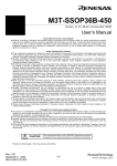
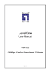
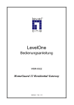
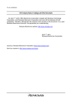
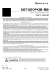
M3T-DUMMY100S
Dummy IC for 100-pin 0.65-mm-pitch QFP
User's Manual
Keep safety first in your circuit designs!
• Renesas Technology Corporation and Renesas Solutions Corporation put the maximum effort into making semiconductor products better and more
reliable, but there is always the possibility that trouble may occur with them. Trouble with semiconductors may lead to personal injury, fire or property
damage. Remember to give due consideration to safety when making your circuit designs, with appropriate measures such as (i) placement of substitutive,
auxiliary circuits, (ii) use of nonflammable material or (iii) prevention against any malfunction or mishap.
Notes regarding these materials
• These materials are intended as a reference to assist our customers in the selection of the Renesas Technology product best suited to the customer's
application; they do not convey any license under any intellectual property rights, or any other rights, belonging to Renesas Technology Corporation,
Renesas Solutions Corporation or a third party.
• Renesas Technology Corporation and Renesas Solutions Corporation assume no responsibility for any damage, or infringement of any third-party's rights,
originating in the use of any product data, diagrams, charts, programs, algorithms, or circuit application examples contained in these materials.
• All information contained in these materials, including product data, diagrams, charts, programs and algorithms represents information on products at the
time of publication of these materials, and are subject to change by Renesas Technology Corporation and Renesas Solutions Corporation without notice
due to product improvements or other reasons. It is therefore recommended that customers contact Renesas Technology Corporation, Renesas Solutions
Corporation or an authorized Renesas Technology product distributor for the latest product information before purchasing a product listed herein. The
information described here may contain technical inaccuracies or typographical errors. Renesas Technology Corporation and Renesas Solutions
Corporation assume no responsibility for any damage, liability, or other loss rising from these inaccuracies or errors. Please also pay attention to information
published by Renesas Technology Corporation and Renesas Solutions Corporation by various means, including the Renesas home page (http://
www.renesas.com).
• When using any or all of the information contained in these materials, including product data, diagrams, charts, programs, and algorithms, please be sure
to evaluate all information as a total system before making a final decision on the applicability of the information and products. Renesas Technology
Corporation and Renesas Solutions Corporation assume no responsibility for any damage, liability or other loss resulting from the information contained herein.
• Renesas Technology semiconductors are not designed or manufactured for use in a device or system that is used under circumstances in which human
life is potentially at stake. Please contact Renesas Technology Corporation, Renesas Solutions Corporation or an authorized Renesas Technology product
distributor when considering the use of a product contained herein for any specific purposes, such as apparatus or systems for transportation, vehicular,
medical, aerospace, nuclear, or undersea repeater use.
• The prior written approval of Renesas Technology Corporation and Renesas Solutions Corporation is necessary to reprint or reproduce in whole or in part
these materials.
• If these products or technologies are subject to the Japanese export control restrictions, they must be exported under a license from the Japanese
government and cannot be imported into a country other than the approved destination. Any diversion or reexport contrary to the export control laws and
regulations of Japan and/or the country of destination is prohibited.
• Please contact Renesas Technology Corporation or Renesas Solutions Corporation for further details on these materials or the products contained therein.
Precautions to be taken when using this product
• This product is a development supporting unit for use in your program development and evaluation stages. In mass-producing your program you have
finished developing, be sure to make a judgment on your own risk that it can be put to practical use by performing integration test, evaluation, or some
experiment else.
• In no event shall Renesas Solutions Corporation be liable for any consequence arising from the use of this product.
• Renesas Solutions Corporation strives to renovate or provide a workaround for product malfunction at some charge or without charge. However, this does
not necessarily mean that Renesas Solutions Corporation guarantees the renovation or the provision under any circumstances.
• This product has been developed by assuming its use for program development and evaluation in laboratories. Therefore, it does not fall under the
application of Electrical Appliance and Material Safety Law and protection against electromagnetic interference when used in Japan.
CAUTION
If the requirements shown in the "CAUTION" sentences are ignored,
the equipment may cause personal injury or damage to the products.
Renesas Tools Homepage http://www.renesas.com/en/tools
Rev. 1.00
May 16, 2003
REJ10J0066-0100Z
(1/4)
1. Outline
The M3T-DUMMY100S is an accessory tool product which
connects the probe of an emulation pod and a target system.
Its dimensions are the same as those of 100-pin 0.65-mmpitch QFP (20 x 14 mm) IC packages (100P6S-A).
(1) M3T-DUMMY100S main unit
2. Package Components (see Figure 1)
(2) Socket main unit
(3) Socket frame
For 100P6S-A,
100P6P-E (formerly 100P6S-E)
(Color: white)
For 100P6S-A
(Color: white)
(1) M3T-DUMMY100S main unit
(2) Socket main unit
(3) Socket frame for 100P6S-A (2 pieces)
(4) M3T-DUMMY100S User's Manual (This manual)
3. Applicable Sockets
The M3T-DUMMY100S has been tested with the following
Figure 1 Package components of the M3T-DUMMY100S
IC sockets made by Matsushita Electric Works, Ltd. Be sure
to use them.
Socket main unit + socket frame (1 set):
AXS4003M295C (for 100P6S-A)
Socket frame for repair (200 pieces):
AXS4002M2 (for 100P6S-A)
(1) Debugging
4. Specifications
(2) Onboard evaluation
Emulator
Table 1 Specifications
Applicable package
Max. permissible
current
100P6S-A
100P6P-E (formerly 100P6S-E)
(100-pin 0.65-mm-pitch QFP)
200 mA at 5 V
Socket frame
for 100P6S-A
Socket frame
for 100P6S-A,
100P6P-E
(formerly 100P6S-E)
M3T-DUMMY100S main unit
MCU (QFP)
20 times guaranteed
Insertion/removal
iterations of connector
Insulation resistance 100M Ω or more
5. Usage (see Figure 2)
The M3T-DUMMY100S can be used for debugging and
onboard evaluation in common by mounting the socket main
unit on the target board.
Socket main unit
(1) For debugging
Mount the socket main unit on the foot pattern of the
target board. And mount the M3T-DUMMY100S and the
socket frame on it. Then attach the connector of the
emulator.
Foot pattern
: No. 1 pin position
Be sure to align the pins.
(2) For onboard evaluation
Mount the socket main unit on the foot pattern of the target
board. Mount an MCU with on-chip flash memory or onetime PROM on it. Then attach the socket frame on it.
Figure 2 Usage of the M3T-DUMMY100S
Before using the M3T-DUMMY100S, be sure to read "8.
Precautions" on page 4.
(2/4)
6. External Dimensions of the M3T-DUMMY100S
Symbol
Dimension [mm]
A
5.0
b
0.4
D
14.0
E
20.0
e
0.65
HD
16.8
HE
22.8
M
6.3
Upper connector J1: AXN650545P
(made by Matsushita Electric Works, Ltd.)
Upper connector J2: AXN550045P
(made by Matsushita Electric Works, Ltd.)
1
1
: Pin number of the M3T-DUMMY100S
: Pin number of the upper connectors
Board
Material: Glass epoxy board
Pin
Material: Bronze phosphide
Plating: Solder plating
Upper connectors
(J1, J2)
Material: Heat tolerant resin (body)
Copper alloy (post, contact)
Plating: Nickel-based gold plating
Figure 3 External dimensions of the M3T-DUMMY100S
7. Sample Foot Pattern of a Target System
Foot pattern recommended by Matsushita Electric Works, Ltd.
Foot pattern for holders (x 4)
(These patterns are essential.)
Note:
Be sure to set up foot patterns for
the holders. Make the thickness
and the area of the solder-print
screen thicker and larger than the
foot patterns recommended so as
to secure a sufficient amount of
solder applied.
(In carrying out manual soldering,
an amount of solder sufficient for
forming a larger fillet than that
formed at the time of reflow is
required.)
As the contacts of the IC
socket body touch the PC
board, thus be sure to give
special consideration to the
patterns of traces so that no
other pins touch the PC
board.
(Through-hole mounting is
not permitted.)
Unit: mm
B
Figure 4 Dimensions of a target foot pattern (Quoted from the specifications of IC socket for QFP by Matsushita Electric Works, Ltd.)
(3/4)
8. Precautions
CAUTION
Cautions to Be Taken for This Product:
•
•
•
•
•
•
•
•
•
When you use the M3T-DUMMY100S, be sure to use it with the socket frame for 100P6S-A.
Do not solder the M3T-DUMMY100S main unit directly on a target board. Be sure to use the included socket.
Before mounting the M3T-DUMMY100S, be sure to check the pin positions.
Holder patterns are required at each of the four corners of the target foot pattern (see Figure 4).
Be sure to solder the holders of the socket. An insufficient amount of solder applied to the holders may
cause a poor contact, so be careful.
For soldering the socket and mounting the M3T-DUMMY100S, refer to the supplement "Mounting the
Socket Included with the M3T-DUMMY100S" and "Note on Handling the M3T-DUMMY100S".
Do not apply an unnecessary stress to the M3T-DUMMY100S.
Do not touch the pins of the M3T-DUMMY100S.
Store the M3T-DUMMY100S in the dedicated case.
IMPORTANT
Notes on This Product:
• We cannot accept any request for repair.
• To remove the socket frame, use the dedicated tool AXY8580N1 made by Matsushita Electric Works,
Ltd. To purchase this product and the socket frame for repair, contact Matsushita Electric Works, Ltd.
(http://www.mew.co.jp/e-index.html)
• For onboard evaluation, choose an appropriate socket frame made by Matsushita Electric Works, Ltd.
listed below.
For 100P6S-A package: Socket frame AXS4002M2 (for 100P6S-A)
For 100P6P-E (formerly 100P6S-E) package: Socket frame AXS4002MA2 (for 100P6P-E)
• For inquiries about this product or the contents of this manual, contact your local distributor.
Renesas Tools Homepage http://www.renesas.com/en/tools
9. Correspondence of the Connectors
Table 2 Correspondence of connectors J1 and J2
Connector
Pin No.
M3T-DUMMY100S
Pin No.
Connector
Pin No.
M3T-DUMMY100S
Pin No.
Connector
Pin No.
M3T-DUMMY100S
Pin No.
Connector
Pin No.
M3T-DUMMY100S
Pin No.
J1-1
J1-2
J1-3
J1-4
J1-5
J1-6
J1-7
J1-8
J1-9
J1-10
J1-11
J1-12
J1-13
J1-14
J1-15
J1-16
J1-17
J1-18
J1-19
J1-20
J1-21
J1-22
J1-23
J1-24
J1-25
79
77
80
81
82
83
84
85
86
87
88
89
90
41
42
43
44
45
46
47
48
49
50
51
52
J1-26
J1-27
J1-28
J1-29
J1-30
J1-31
J1-32
J1-33
J1-34
J1-35
J1-36
J1-37
J1-38
J1-39
J1-40
J1-41
J1-42
J1-43
J1-44
J1-45
J1-46
J1-47
J1-48
J1-49
J1-50
53
54
55
56
57
58
59
60
61
62
63
64
65
66
67
68
69
70
71
72
73
74
75
76
78
J2-1
J2-2
J2-3
J2-4
J2-5
J2-6
J2-7
J2-8
J2-9
J2-10
J2-11
J2-12
J2-13
J2-14
J2-15
J2-16
J2-17
J2-18
J2-19
J2-20
J2-21
J2-22
J2-23
J2-24
J2-25
3
5
6
7
8
9
10
11
12
13
14
15
16
17
18
19
20
21
22
23
24
25
26
27
28
J2-26
J2-27
J2-28
J2-29
J2-30
J2-31
J2-32
J2-33
J2-34
J2-35
J2-36
J2-37
J2-38
J2-39
J2-40
J2-41
J2-42
J2-43
J2-44
J2-45
J2-46
J2-47
J2-48
J2-49
J2-50
29
30
31
32
33
34
35
36
37
38
39
40
91
92
93
94
95
96
97
98
99
100
1
4
2
(4/4)