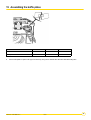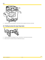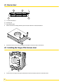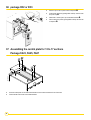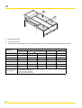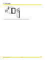
1
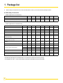
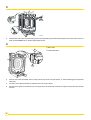
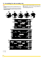
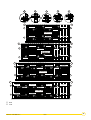
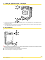
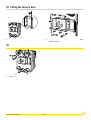
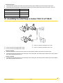
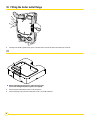
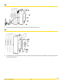
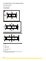
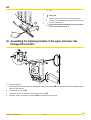
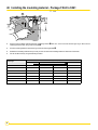
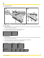
EN Remeha Fuel oil/gas boilers P 520 Assembly Instructions 300016864-001-C 63118 1 Package list ` Before starting to assemble the boiler, refer to the table below to check if you have received all the packages required. Boiler body + Accessories • Boilers supplied with an assembled body • Boiler P 520 - Number of sections 13 15 17 19 21 23 25 Assembled boiler body (contents depend upon model) 1 1 1 1 1 1 1 Cleaning tool kit (contents depend upon model) 1 1 1 1 1 1 1 Boiler P 520 - Number of sections 13 15 17 19 21 23 25 Base frame (dimensions depend upon model) 1 1 1 1 1 1 1 Rear section 1 1 1 1 1 1 1 Normal intermediate section 8 10 12 14 15 17 19 Special intermediate section 3 3 3 3 4 4 4 Front section 1 1 1 1 1 1 1 Set of assembly rods + Cleaning tools (contents depend upon model) 1 1 1 1 1 1 1 Boilers supplied with an unassembled body Standard accessory kit (contents depend upon model) 1 package FA 48 FA 50* FA 52* FA 54* FA 56 FA 58 FA 60 Additional accessory kit (contents depend upon model)** 1 package FA 67** FA 69 FA 71 FA 73 FA 75 FA 77 FA 79 1 1 1 1 1 1 1 1 1 1 1 1 1 1 Plain furnace plate Ø 300 Flue gas connection plate with opening Ø 350 Ø 400 Plain flue gas connection plate Flue gas box 1 Distributing tube fitting* 1 1 1 1 1 1 * * * 1 1 1 *The distributing tube fitting for P 520 boilers with 15 to 19 sections is included in the accessory package. **The diaphragm for P 520 , 13 and 14 section boilers is delivered in the additional accessory kit package. 2 P 520 25/01/2012 - 300016864-001-C Baffle plates Boiler P 520 - Number of sections Baffle plates 13 15 17 19 1 1 1 1 1 1 13 15 17 1 1 1 package CM 22 package CM 23 23 25 1 2 2 2 19 21 23 25 1 1 1 1 1 1 1 2 1 Casing fittings Boiler P 520 - Number of sections package RC 2 package RC 3 Casing fittings package MR 4 1 package MR 5 1 package FA 10 2 1 1 2 1 2 1 2 3 2 3 15 17 19 21 23 25 package FA 16 1 1 1 1 package FA 18 1 package FA 11 21 Casing, variable parts Boiler P 520 - Number of sections 13 package FA 20 1 package FA 22 package FA 23 1 1 package FA 24 1 package FA 25 1 package FA 27 1 Insulating material for body Boiler P 520 - Number of sections 13 package FA 34 15 19 21 23 1 package FA 36 1 package FA 37 1 package FA 39 1 package FA 40 1 package FA 41 25 1 package FA 35 Insulation 17 1 Control panel Boiler P 520 - Number of sections Control panel 25/01/2012 - 300016864-001-C package RC 6 13 15 17 19 21 23 25 1 1 1 1 1 1 1 P 520 3 Accessories - Available as an option Boiler P 520 - Number of sections 13 15 17 19 21 23 25 Furnace plate with hole Ø 165/ 186/ 210/ 240 or Ø 295 1 1 1 1 1 1 1 Connecting plate with Ø 300 opening or plain connecting plate or Plain connection plate 1 1 1 1 1 1 1 1 1 1 1 1 1 1 Set of anti-vibration studs 8208-7758 8208-7759 8208-7760 4 Refer to the applicable price list for the other optional features (control units etc.) which may be used with these boilers. P 520 25/01/2012 - 300016864-001-C 2 Mounting Warning: Assemble the boiler in the order given by the numbers of each figure, in compliance with all the instructions . Tools required - Refer to the applicable price list for any optional features used. 1 JD-TE or JD-TE Plus assembly tool 1 Flat screwdriver 1 "n°2 posidrive" screwdriver 1 10, 13, 17, 19 spanners 1 22 tubular box spanner 1 27 tubular box spanner 1 electric screwdriver + 1 "n°2 Philipps" screwdriver bit 1 Stanley knife Silicone filler (Supplied) Boilers supplied with an assembled body - Hydraulic test: See fig. 18 - Mounting: start assembly from figure 35 Mounting the boiler body: - Assemble the boiler body from the rear to the front: assemble the rear section, assemble all the normal intermediate sections, assemble all the special intermediate sections, assemble the front section. The number of sections of each type is provided in the table below 104 Section type 8228-0004 111 151 104 2 3 4 8228-0001 8228-0002 8228-0003 P 520-13 1 8 3 1 P 520-15 1 10 3 1 P 520-17 1 12 3 1 P 520-19 1 14 3 1 P 520-21 1 15 4 1 P 520-23 1 17 4 1 P 520-25 1 19 4 1 Rear section Normal intermediate section Special intermediate section Front section 25/01/2012 - 300016864-001-C P 520 5 1 1 2 3 3 3 D E S DE OB SS TO EN US P S T AN AV VORN NT O FR U S 3 O B E N D - E T U P S O S 2 S - O BE FRONTRN VO NT AVA N DE O SS TO BEN US P T AN AV VORN NT O FR O -T 3 P FRONTN M0 VOR AVANT 00 05 19 6 M000309 ` to : Assembly of the base frame, delivered unassembled. ` Place the frame on the floor, taking care to note the TOP and FRONT positions. ` Fit the fastening brackets as shown, depending on the type of boiler (1 Screw Ø 12x40 - 19 spanner). 6 P 520 25/01/2012 - 300016864-001-C 2 M000057 ` Establish the location of the frame on the basis of the opening direction of the furnace door and the length of the burner. Leave enough clearance at the rear of the boiler for water connections and the distributing tube. ` Fit the rear section on the frame, behind the fastening brackets (see detailed drawing) and prop it up. ` Insert the lower assembly rods in the holes of the rear section and the fastening brackets of the frame, in order to position the rear section correctly according to the frame 3 M0 ` 0 00 58 Clean all the openings in the section with a brush. Remove any deposit on the bottom of the section. 25/01/2012 - 300016864-001-C P 520 7 4 100 ` 100 100 M000059 a 100 Fill the bottom of the U groove (located on the periphery of the section) with a continuous bead of DOW CORNING silicon, diameter approximately Ø 5 mm. Caution: silicon must not be applied 100 to either side of the connection (nipple assembly area). M000060 5 ` Fit the Ø 10.5 mm diameter thermocord into this U groove and into the groove which circles the furnace. Note: Do not pull on the seal while inserting it. Otherwise, you may stretch it and reduce its thickness. 8 P 520 25/01/2012 - 300016864-001-C 6 Handle the nipples with gloves, there might be sharp edges. Clean the bores and nipples with diluent. Remove any traces of rustprotective paint so that the surface is perfectly smooth. Coat with the lubricant supplied with the sections. M000062 7 A R R IÈ R R E A R E R D IÈ S E S U S - S E B E O D N S - U T S O - P O B A E V N A O T T N P AV A N T ` Gently push in the 2 nipples. 25/01/2012 - 300016864-001-C P 520 9 8 a 1 00 100 1 00 100 M000063 Fill the bottom of the W groove opposite the U groove for the intermediary parts (located on the periphery of the section) with a continuous bead of DOW CORNING silicon, diameter approximately Ø 5 mm. ` 9 Rear section 1 Intermediate section M000064 2 ` Place the first normal intermediate section, making sure that it is turned in the right direction, i.e. with the flattening groove against the thermocord. ` For safety, insert a lateral assembly rod (supplied) in the holes of the 2 sections. ` Push the section gently and simultaneously on the 2 nipples of the rear section with a hammer and a piece of wood positioned in line with the bores. 10 P 520 25/01/2012 - 300016864-001-C 10 M000065 ` Put the assembly tool in position. Tighten gradually so as to bring together the upper and lower connections evenly and simultaneously. 11 M000066 ` Assemble the remaining intermediate sections one by one, to the procedure stated in figures 3, 4, 5, 6, 7, and 8. ` First assemble the normal intermediate sections, then the special ones. Leave the assembly tool in place. 25/01/2012 - 300016864-001-C P 520 11 12 M000067 ` Trim off any projecting ends of the thermocords the sweeping covers. M000068 13 Fitting the upper and lower assembly rods 2 ` On the lower assembly rods, fit the following at each end in the given order : an expansion spring, a washer and a nut (the holes of the front lugs must be aligned with the holes of the frame brackets as the assembly rods are used to make the boiler body integral with the frame). ` Stop tightening as soon as the gap between the spring spires is equal to about 2 mm. 12 P 520 25/01/2012 - 300016864-001-C 14 1 2 Rear Front 2 2 M000069 ` Put in place the upper assembly rods in the two front and rear lugs. ` Mount the 2 crosspieces (supplied in package FA 5/6) with their bends turned backwards and fasten them to the rods with an expansion spring, 1 nut and 1 washer ` Remove the assembly tool. 25/01/2012 - 300016864-001-C P 520 13 15 Assembling the side assembly rods - Place the expansion spring and washer on the rear of each rod. - Stop tightening the nuts as soon as the gap between the spires of the springs is about 1 mm. - The side assembly rods must be assembled from the rear to the front. - The rods must be inserted in the holes stated in the diagrams (the lugs of the sections in which the assembly rods are to be inserted have 2 holes). A B D C E A 1 mm 1 mm 1 mm 1 mm 1 2 520 mm C A 300 mm D 520 mm 420 mm B C P520-13 A 520 mm 520 mm C 300 mm D 420 mm C B 1 2 520 mm C A D 520 mm 520 mm 420 mm C B P520-15 520 mm C A D 520 mm 520 mm 420 mm C B 2 1 E C 420 mm D D 420 mm C 520 mm 520 mm B 420 mm P520-17 E 420 mm D C 420 mm 520 mm C D 420 mm 520 mm B M000072 Rear Front 14 P 520 25/01/2012 - 300016864-001-C A B D C E A 1 mm 1 mm 1 mm 1 mm 1 2 C 520 mm E D C 520 mm D 520 mm 520 mm B 420 mm P520-19 C 520 mm E D C 520 mm D 520 mm 520 mm B 420 mm 1 2 520 mm C A C 520 mm D 420 mm C D 520 mm B 385 mm 520 mm P520-21 520 mm C A C D 420 mm 520 mm C D 520 mm B 385 mm 520 mm 1 2 420 mm E D C 420 mm 420 mm D 520 mm C D 520 mm C 520 mm B 385 mm P520-23 420 mm E D C 420 mm 420 mm D 520 mm C D 520 mm C 520 mm B 385 mm 1 E 2 420 mm D C 520 mm D 520 mm C 520 mm C D 520 mm 520 mm B 385 mm P520-25 E 420 mm D C 520 mm 520 mm D 520 mm C D 520 mm C 520 mm B 385 mm M000073 Rear Front 25/01/2012 - 300016864-001-C P 520 15 16 Assembling the pocket and the plugs P520-13/15/17/19 1 P520-21/23/25 M000074 Safety pressure sensitive switch Assembling the safety pressure sensitive switch only valid for the Netherlands ! ` Assemble the pocket for the thermostats and thermometer in: • the third special intermediate section - 150 mm wide, 1/2’’ hole for P 520-13 to P 520-19 or • ` 16 the fourth special intermediate section - 150 mm wide, 1/2’’ hole for P 520-21 to P 520-25. Plug the 2 free 1/2’’ holes for P 520-13 to P 520-19 or the 3 free 1/2’’ holes for P 520-21 to P 520-25 in the special intermediate sections. P 520 25/01/2012 - 300016864-001-C M000075 17 Fitting the upper and lower front flanges ` Fit the plain flange onto the upper connection of the front section (using 4 H 18 nuts), with the Ø 170x222 gasket in between (first soak the gasket in warm water). ` Fit the flange with the sludge removal hole onto the lower connection of the front section (hole in the lower part of the flange) using 4 H 18 nuts, with the gasket in between (soak in warm water first). 18 Hydraulic test 1. 1 2 M0 000 76 After assembling the boiler body, the installer must carry out a water tightness test at a pressure equal to 1.3 times the operating pressure (that is 9.75 bar mini) for 10 minutes at least. Fit a square flange with hole facing upwards onto the upper flange with outlet piece. Fit a blind square flange onto the lower flange with return piece. 25/01/2012 - 300016864-001-C P 520 17 2. 4 3 2 M0 000 77 Ensure that all the air in the boiler is vented to avoid any bursting of the body. 3. 7 5 8 7 11 M0 0 00 78 66 9 7,8 10 0 bar ` Maintain pressure for at least 10 minutes. Any drop in pressure indicates a leakage in the boiler body. ` After the tightness test, drain the boiler and remove all the parts used for the test. 18 P 520 25/01/2012 - 300016864-001-C 19 Assembling the baffle plates M000079 Boiler P 520 - Number of sections Total number of baffle Package no. ` P 520-13 P 520-15 to 19 P 520-21 to 25 4 6 8 CM 23 CM 22 + CM 23 2 x CM 23 Put the baffle plates into place in the upper front flue ways, taking care to interlock them with each other before fitting them. 25/01/2012 - 300016864-001-C P 520 19 20 Assembling the sweeping covers - The covers are numbered from 1 to 4, and must be fitted with a thermocord . The length of the thermocord depends upon the cover and is given below. 1 2 2 1 4 3 Type Thermocord length 1 1335 mm 2 1110 mm 3 890 mm 4 665 mm Place the 2 no. 1 sweeping covers (with the handles turned outward ) on either side of the boiler starting from the front. Distribute the other covers evenly. 3 M000080 Rear Front - Clean off the protective varnish on the ground surfaces with diluent. Cover model Boiler type 20 No. 1 Each cover is fitted with a system whereby it can only be mounted with the handles turned outward. - Fit the two locks of each cover between the sections. - Push the cover towards the outside of the boiler, to the closed position . - Fasten the two brass nuts of each cover . No. 2 No. 3 No. 4 Number of sweeping covers per type Front Rear P 520-13 2 4 P 520-15 2 4 P 520-17 2 6 P 520-19 2 6 P 520-21 2 8 P 520-23 2 6 P 520-25 2 10 2 2 4 P 520 25/01/2012 - 300016864-001-C M000081 21 ` Insert the thermocord in the sealing groove on each side and hold it in place with a few drops of silicone filler. M000082 22 Putting in place the lower trap doors ` Insert the thermocord in the sealing groove of the 2 lower flue ways, on the rear and front of the boiler. ` Put the 4 trap doors on the lower flue ways and fasten with the wing nuts. 25/01/2012 - 300016864-001-C P 520 21 2 7 mm 23 Burner door 3 M000083 1 1 2 screws SIM 3.94x25.4 Refractory felt Rigid refractory plate ` Put the furnace door insulating material in place and retain it with the 4 screws SIM 3.94x25.4. M0 ` 00 08 4 Place the furnace door on the floor and fasten the articulation onto the door with 3 screws HM 12. M000085 24 Installing the hinge of the furnace door ` 22 Fix the furnace door hinge on the right or left-hand side of the front section by means of 3 screws HM 12x25. P 520 25/01/2012 - 300016864-001-C 25 Fitting the furnace door 2 ` ` Fit the door onto the hinge by inserting the pin. M000087 M000086 1 Close the furnace door on the 8 studs and fasten with 8 washers and nuts. M000088 26 ` Fit the 2 doors of the upper flue ways (wing nuts). 25/01/2012 - 300016864-001-C P 520 23 27 Flame inspection window M000089 ` The flame inspection window is fitted with a 1/4" tapped hole for ventilation (optional): if a ventilation system is used, connect the hole to the one provided for that purpose before the burner combustion head. M0 00 09 0 28 Assembling the return flange on boilers P 520-13 to P 520-25 1 2 L 3 4 P 520-13: Package FA 67 P 520-13: Package FA 48 P 520-15 to P 520-25: Package FA 69 to FA 79 P 520-15 to P 520-25: Package FA 50 to FA 60 • P 520-13 Fit the water balancing diaphragm with the notches vertical onto the boiler return with a Ø 170x222 gasket in between (first soak the gasket in warm water). Fit the heating return flange with a Ø 170x222 gasket in between and fix it with 4 nuts H 18. 24 P 520 25/01/2012 - 300016864-001-C • P 520-15 to P 520-25 ` Fit the water balancing tube onto the boiler return with a Ø 170x222 gasket in between (first soak the gasket in warm water). ` Fit the heating return flange with a Ø 170x222 gasket in between (first soak the gasket in warm water) and fix it with 4 nuts H 18. Boiler type Length mm P 520-15 380 P 520-17 and P 520-19 600 P 520-21 880 P 520-23 and P 520-25 1210 4 M000091-B 29 Assembling the outlet flange on boilers P 520-13 to P 520-25 P 520-17 to P 520-25: Package FA 51 to FA 60 P 520-13 to P 520-15: Package FA 42 to FA 50 P 520-17 to P 520-25: Package FA 70 to FA 79 P 520-13 to P 520-15: Package FA 61 to FA 69 • P 520-13 to P 520-15 ` Place the nozzle turned outside from the boiler with a Ø 170x222 gasket in between (first soak the seal in warm water). ` Assemble the flange with angled piece so that the angle is turned upward, with a Ø 170x222 gasket in between (first soak the gasket in warm water) and fasten with 4 nuts H 18. • P 520-17 to P 520-25 ` Assemble the flange with angled piece so that the angle is turned upward, with a Ø 170x222 gasket in between (first soak the gasket in warm water) and fasten with 4 nuts H 18. 25/01/2012 - 300016864-001-C P 520 25 30 Fitting the boiler outlet flange M0 ` 00 0 92 Carefully insert the Ø 15 gasket in the groove of the rear section and hold it in place with a few drops of silicone. 31 Before assembling the flue gas box, grease all bolts, studs and screws with high-temperature grease (not supplied). ` Put the adhesive sheet gasket in place on the flue gas box. ` Put the sweeping cover in place and fasten with 2 nuts H 10 and Ø 10 washers. 26 P 520 25/01/2012 - 300016864-001-C 32 ` The flue gas outlet is fastened to the rear by means of 6 studs, washers and Ø 12 nuts. 33 M0000 95 ` First adapt the steel connecting plate to the chimney connection flue, then fasten that plate or the plate with a connecting piece with 10 nuts H10 and Ø10 washers. 25/01/2012 - 300016864-001-C P 520 27 34 Assembling the flow switch M0 96 Fasten the flow switch on the sleeve tube. The direction of the arrow head on the collet must be the same as the flowing out of the water in the tube. ` 28 000 Number of sections Flow switch Code no. 13 8802-4743 15 8802-4746 17 8802-4738 19 8802-4753 21 8802-4755 23 8802-4757 25 8802-4759 P 520 25/01/2012 - 300016864-001-C 35 Assembling the baffle plates Boilers supplied with an assembled body for boilers supplied with an assembled body only. Only NL: Mounting of the low-water safety pressure switch! (Refer to the leaflet "Mounting of the low-water safety pressure sensitive switch" delivered in the package) M000097 ` Put the baffle plates into place in the upper front flue ways, taking care to interlock them with each other before fitting them. Boiler P 520-13 P 520-15 to P 520-19 P 520-21 to P 520-25 4 6 8 CM 23 CM 22 + CM 23 2 x CM 23 Total number of baffle Pack no. 36 Assembling the upper crosspieces - package RC2 or RC3 Boilers supplied with an assembled body Rear Front 1 2 2 for boilers supplied with an assembled body only. 2 2 ` M000098 1 Mount the 2 crosspieces and fasten them onto the rods with an expansion spring, 2 nut and 2 washer. 25/01/2012 - 300016864-001-C P 520 29 37 Assembling the top insulating material - 13 to 17 sections Package FA34 to FA41 Front - Put in place the 600 mm wide (packages FA30 to FA36) top insulating material on the body of the boiler. 80 Number of sections 13 15 17 Length (mm) 1800 2100 2200 M000099 90 1 38 Assembling the cable channels - 13 to 17 sections Package FA23, FA25, FA27 Rear 1 M 00 01 00 AVANT ` Place the cable channels so that their bevelled end is to the front. ` Fasten with 2 screws H8 x 16 + L8 washers in the third hole starting from the front and opposite the special nut. ` Fasten at the rear with 2 screws H8 x 16 + L8 washers opposite the oblong holes and special nut. 30 P 520 25/01/2012 - 300016864-001-C 39 Assembling the top insulating material - 19 to 25 sections Package FA37, FA39, FA40, FA41 80 M000101 90 ` Put in place the 2 pieces of insulating material (width 600 mm, packages FA37 to FA41) on the body of the boiler. ` Push the insulating material under the front and rear crosspieces. Number of sections 19 21 23 25 Length (mm) 2 x 1200 2 x 1400 2 x 1500 2 x 1600 M000012 40 Assembling the intermediate piece - 19 to 25 sections Package RC3 ` Assemble the intermediate piece on the assembly rods by fitting one slotted side onto one rod and using the flexibility of the other rod. 25/01/2012 - 300016864-001-C P 520 31 41 Assembling the cable channels - 19 to 25 sections Package FA16 and Package FA18, FA20, FA22, FA24 Package FA16 Package FA18, FA20, FA22, FA24 1 2 M000103 A Number of sections 19 21 23 25 Length (mm) 2600 2910 3110 3310 ` Place the cable channels so that their bevelled end is to the front. ` Fasten with 2 screws H8 x 16 + L8 washers in the third hole starting from the front and opposite the special nut. ` Fasten them to the intermediate piece and the rear crosspieces with 2 screws H8 x 16 and L8 washers. ` Align the 2 additional cable channels with the two others. ` Fasten them to the intermediate piece and the rear crosspieces with 4 screws (H8 x 16) and L8 washers. 42 Assembling the casing positioning brackets package RC2 or RC3 M 00 ` 32 01 04 Fasten the positioning brackets (package RC2 or RC3) onto the right and left-hand upper bosses of the front section with: 2 screws H8 x 16 + 2 serrated washers (13 mm spanner). P 520 25/01/2012 - 300016864-001-C 43 Assembling the lower rail support brackets package RC2 or RC3 Example for a P 520-13 M000105 1 ` Fasten the lower rail support brackets using H8 x 16 screws + Serrated washer. for the assembly direction, see the drawings below. 25/01/2012 - 300016864-001-C P 520 33 Assembly direction of lower rail support brackets (seen from the top of the frame) A: 13, 15 and 17 sections B: 19 and 21 sections C: 23 and 25 sections A 3 5 1 6 2 4 3 1 2 6 4 3 6 1 2 4 M000106 Rear Front Right-hand side Left-hand side Rail support brackets Base frame 34 Note: 2 lower rail support brackets and 2 upper rail brackets are left unused with 19 and 21 sections. P 520 25/01/2012 - 300016864-001-C 44 Front see fig. 46 ` Fasten the lower rail with H8 x 30 screws and L8 washers. ` The other rail support brackets are fastened opposite the holes provided on the lower rail. 1 Length required while assembling the 2-piece rails (boilers with 19 to 25 sections), see fig. 47. M 00 01 07 45 Assembling the fastening brackets of the upper and lower rails Package RC2 and RC3 44 1 1 M000108 33 ·2 · 2 ·2 1 Imperative alignment. ` Fix the fastening bracket of the upper rails (package RC2 or RC3) on the upper lug (these brackets must be vertically aligned with the lower rail support brackets). ` Fit the bracket onto the stub . ` Fasten with 1 screw H10 x 50 and serrated washers and H10 nuts . ` Assemble 1 "Rapid" nut on the top of the bracket with the tapped shaft on the inside. 25/01/2012 - 300016864-001-C P 520 35 46 Installing the insulating material - Package FA34 to FA41 Front 1 1 90 3 220 2 M000109 ` Place the side insulating material against the positioning bracket and cut it so that it is flush with the upper lug on which the rail fastening bracket is fixed, along a 220 mm length . ` Push the insulating material in behind the lug and the rail fastening bracket . ` Distribute the insulating material evenly so that you have the same side insulating material on either side of the boiler. ` Cut the insulation similary along the fastening brackets. Boiler type 36 Side insulating material (mm) Front Rear P 520-13 1200 600 P 520-15 1200 400 400 P 520-17 1200 400 600 P 520-19 1200 1200 P 520-21 1200 400 1200 P 520-23 1200 600 1200 P 520-25 1200 400 400 P 520 1200 25/01/2012 - 300016864-001-C 47 Example with P 520-17 A B 1 5 5 2 M000110 A 4 5 5 Rear Front 13 to 17 sections ` Fix the upper rail with H8 x 30 screws and L8 washers (the first hole from the front end of the rail must be opposite the first fastening bracket, and similarly with the other brackets). ` Push the insulating material behind the lower rail and underneath the boiler. ` Join the pieces of insulating material to each other with the clips. Number of sections package 13 FA 23 15 FA 25 17 FA 27 19 to 25 sections: ` Fix the upper rail with H8 x 30 screws and L8 washers (the first hole from the front end of the rail must be opposite the first fastening bracket, and similarly with the other brackets). ` Fix the additional upper and lower rails, making sure you comply with dimension A (see table below). ` Push the insulating material behind the lower rail and underneath the boiler. ` Join the pieces of insulating material to each other with the clips. Number of sections package package 19 FA 16 FA 18 21 FA 16 FA 20 23 FA 16 FA 22 25 FA 16 FA 24 Number of sections 19 21 23 25 A (mm) 2615 2875 3075 3275 25/01/2012 - 300016864-001-C P 520 37 48 Assembling the side casing panels Package FA142 to FA143 and FA10 to FA11 3 5 2 1 M000111 2 4 ` First assemble the panels on the front using the assembly length table opposite and continue up to the rear section . ` Fix the front side panels to the positioning brackets with H8 x 16 screws and serrated washers . ` Push the insulating material into the top of the side panels and fasten the panels to the lower rails by means of the self-drilling screws with the electric screwdriver (2 screws per panel) . ` Fasten the side panels to each other with the clips. Side panels - Grey (mm) Boiler type Rear P 520-13 1050 400 400 P 520-15 940 600 600 P 520-17 940 600 400 400 P 520-19 940 600 600 400 P 520-21 1050 600 600 600 P 520-23 1050 600 600 400 400 P 520-25 1050 600 600 600 400 Panels 38 Front (light grey) 400 mm long panel in package FA10 600 mm long panel in package FA11 940 mm long panel in package MR4 1050 mm long panel in package MR5 P 520 25/01/2012 - 300016864-001-C 49 Assembling the furnace door and lower crosspiece panels package RC2 or RC3 Put the furnace door panel in place (package RC2 or RC3) and fasten with 2 tapping screws (Ø 3.94 x 12.7). The furnace door panel may be cut in 2 at the micro-joints. 1 M000112 Fix the casing support lower crosspiece (package RC2 or RC3) by means of 2 screws (H6 x 20) and 2 serrated washers. 2 50 Assembling the control panel bracket (all control panels) package RC2 or RC3 2 1 2 3 M000113 ` Fit the 4 "Rapid" nuts on the front of the cable channels. ` Fit the "Rapid" nuts in the slots : 4 "Rapid" nuts for 13 to 17 sections. 8 "Rapid" nuts for 19 to 25 sections. ` Fix the control panel bracket (package RC2 or RC3) underneath the 2 cable channels by means of 2 screws (H8 x 16) and 2 serrated washers. 25/01/2012 - 300016864-001-C P 520 39 51 package RC2 or RC3 M0 ` 40 00 11 4 Put the front crosspiece in place (package RC2 or RC3) and fasten with 2 screws (H8x16) and 2 tapping screws (Ø 3.94 x 12.7) + serrated washers. P 520 25/01/2012 - 300016864-001-C 52 Package RC6 25/01/2012 - 300016864-001-C P 520 41 53 Control panel assembly (1) 1 2 M0 00 (2) 5 11 Position the control panel on the front studs. Open the control panel (2 screws on the side). 54 Burner cable M000116 ` 42 Bring the burner cable behind the casing support and down to the burner between the side panel and insulating material. P 520 25/01/2012 - 300016864-001-C M000117 55 Installing the bulbs ` Fix the control panel to the rear of the control panel bracket using 2 screws (H Ø 4 x 40) and serrated washers. ` Carefully unroll the various bulbs and bring them out of the control panel through the opening in the bottom on the panel. 56 M00 0118 ` Cut out the top insulating material to free the boiler pocket. Then, insert the bulbs inside the pocket and maintain them with the spring. Only NL: Connect the safety pressure sensitive switch option. 57 All connections are made with the terminal boxes designed for that purpose on the back of the boiler's command board. See the “Electrical Connections” section of the instructions Zsupplied with the control panel. 25/01/2012 - 300016864-001-C P 520 43 58 Installing the insulating material M000119 ` Put in place the insulating material as shown above. 59 Section A-A: package RC2 or RC3 Mounted screw A-A Control panel trim 4 Serrated washer 5 "Rapid" nut Cable channel 6 Control panel bracket 7 3 Front crosspiece 2 1 A M0 00 12 0 2 A ` Unfasten the screws (mounted in fig. 50). ` Slide the control panel trim along the screws . ` Fasten the screws . 44 P 520 25/01/2012 - 300016864-001-C 60 package RC2 or RC3 ` Fix the trim to the control panel using 2 tapping screws and serrated washers. M000122 61 package RC2 or RC3 ` Place the insulating material in the lower central front panel (black cloth facing outward). ` Fit the lower central front panel (package RC2 or RC3) onto the lower front crosspiece and fix it to the furnace door panel. 25/01/2012 - 300016864-001-C P 520 45 M000123 62 package RC2 or RC3 ` Fit the left and right-hand side front panels (package RC2 or RC3) onto the lower front crosspiece and fit them onto the studs of the side panels. M000124 63 package RC2 or RC3 ` Place the retaining crosspiece (package RC2 or RC3) on the left and right-hand front panels, taking care to place the 2 central tabs behind the furnace door panel. ` Fit the upper front panel (package RC2 or RC3) onto the side panels via the 4 studs. 46 P 520 25/01/2012 - 300016864-001-C M000125 64 package RC2 or RC3 10 ` Put in place the insulation of the flue gas box and the lower rear insulating material (package RC2 or RC3). If the side crosspieces overlap at the rear by more than 10 mm, we advise you to saw them off using a hacksaw. 65 package RC2 or RC3 M0 00 12 6 Put in place the 2 rear crosspieces (package RC2 or RC3)behind the bend of the rear side panels and fasten each crosspiece to the side panels using 2 screws (Ø 3.94 x 12.7). 25/01/2012 - 300016864-001-C P 520 47 66 package RC2 or RC3 1 2 3 ` Put the 2 clip-on nuts in place on the side panels . ` Fit the upper rear panel (package RC2 or RC3) onto the studs and push it up . ` Fasten with 2 screws (H8 x 16) and serrated washers . ` Fit the 2 lower rear panels (package RC2 or RC3) onto the rear crosspieces . 4 M0 00 12 7 M000128 67 Assembling the central plate for 13 to 17 sections Package FA23, FA25, FA27 ` Place the central plate on the cable channels with the round holes towards the front of the boiler. ` Fasten with H8 x 30 screws and serrated washers. 48 P 520 25/01/2012 - 300016864-001-C 68 Assembling the central plate for 19 to 25 sections Package FA18, FA20, FA22, FA24 2 Package RC3 Package FA16 3 1 2 M0 1 00 12 9 3 3 ` Place the rear plate, which is 1200 mm long . ` Fasten with 2 screws (H8 x 30) and serrated washers. ` Place the front plate with the round holes towards the front of the boiler . ` Fasten with 4 screws (H8 x 30) and serrated washers. ` Fasten the joining plate with the round holes towards the front of the boiler with 4 tapping screws and serrated washers. 69 Package FA34 to FA41 M0 0 01 ` 30 Put in place the sweeping cover insulating material(packages FA34 to FA41): - P 520-13 to P 520-17: 2 pieces. - P 520-19 to P 520-25: 4 pieces. 25/01/2012 - 300016864-001-C P 520 49 70 1 M000131 2 Package MR4 to MR5 Package FA10 to FA11 ` Place the side covers (package FA7 to FA11, see table) from the front to rear. They have the same lengths as the side panels. Boiler type Front Rear P 520-13 1050 400 400 P 520-15 940 600 600 P 520-17 940 600 400 400 P 520-19 940 600 600 400 P 520-21 1050 600 600 600 P 520-23 1050 600 600 400 400 P 520-25 1050 600 600 600 400 Cover packages 50 Central and boiler side covers (mm) 400 mm long panel in package FA10 600 mm long panel in package FA11 940 mm long panel in package MR4 1050 mm long panel in package MR5 P 520 25/01/2012 - 300016864-001-C 71 Data plate M000048-B ` Glue the rating plate and CE marking on the casing of the boiler in an easily visible location. 25/01/2012 - 300016864-001-C P 520 51 © Copyright All technical and technological information contained in these technical instructions, as well as any drawings and technical descriptions supplied, remain our property and shall not be multiplied without our prior consent in writing. Subject to alterations. 25/01/2012 300016864- 001- C