1
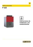
EN Remeha Fuel oil/gas boilers P 420 Assembly Instructions 300016854-001-A 63193 1 Package list Package list : Before starting to assemble the boiler, refer to the table below to check if you have received all the packages required. 1. Boiler body + Accessories Boilers supplied with an assembled body Number of sections 8 9 10 11 12 13 14 Assembled boiler body - (contents depend upon model) 1 1 1 1 1 1 1 Number of sections 8 9 10 11 12 13 14 Front section 1 1 1 1 1 1 1 Special intermediate section 1 1 1 1 1 1 1 Normal intermediate section 5 6 7 8 9 10 11 Rear section 1 1 1 1 1 1 1 For boiler supplied with the boiler body in bulk Common accessories 1 Package CS 20 CS 20 CS 20 CS 20 CS 20 CS 20 CS 20 Lower insulation, boiler body 1 Package CS 51 CS 53 CS 53 CS 55 CS 55 CS 57 CS 57 1 1 1 1 1 1 1 8 9 10 11 12 13 14 CS 30 CS 31 CS 31 CS 32 CS 32 CS 33 CS 33 8 9 10 11 12 13 14 Base frame - dimensions depend upon model 2. Baffle plates Number of sections Baffle plates 1 Package 3. Casing Number of sections Casing (common parts) Package RB2 1 1 1 1 1 1 1 Casing, variable parts Package MP2 - - 1 - - 1 - Package MP3 1 - - 1 - - 1 Package MP4 - 1 1 1 2 2 2 Package MP5 - 1 - - 1 - - 8 9 10 11 12 13 14 CS 41 CS 42 CS 43 CS 44 CS 45 CS 46 CS 47 8 9 10 11 12 13 14 1 1 1 1 1 1 1 4. Cable channel Number of sections Cable channel 1 Package 5. Control panel RC 1 6. Technical documents Number of sections Technical documents (Content depends upon country) 2 1 Package P 420 02/04/08 - 300016854-001-A 2 Boilers supplied with an assembled body Manoeuvring the assembled boiler body To manoeuvre the assembled body, it is possible to use the four lifting rings located on the frame. Mounting: For boilers with assembled boiler body, start assembly from figure 16 Hydraulic test: Refer to view 10 Certain parts will have to be removed to carry out the hydraulic test. 3 Mounting Warning : Assemble the boiler in the order given by the numbers of each figure, in compliance with all the Refer to the applicable price list for any optional features used. instructions. Tools required - 1 22 box spanner 1 Phillips screwdriver 1 hammer 1 putty gun 1 stanley knife 13 - 19 - 24 spanners 1 Allen key JDTE or JDTE Plus assembly tool 02/04/08 - 300016854-001-A P 420 3 Boilers supplied with an assembled body • Hydraulic test: Refer to view 10 Certain parts will have to be removed to carry out the hydraulic test. • Mounting: For boilers with assembled boiler body, start assembly from figure 16 For boiler supplied with the boiler body in bulk Hydraulic test: Refer to view 10 Mounting: Assembly of the sections is done from back to front as shown below, beginning with assembly view 1 Front - Rear Rear section Special intermediate section Normal intermediate section Front section P 420-8 1 1 5 1 P 420-9 1 1 6 1 P 420-10 1 1 7 1 P 420-11 1 1 8 1 P 420-12 1 1 9 1 P 420-13 1 1 10 1 P 420-14 1 1 11 1 Boiler type 4 P 420 02/04/08 - 300016854-001-A 1 Assembly of the base frame, delivered unassembled 1 M001233 2 3 2 3 M001234 02/04/08 - 300016854-001-A P 420 5 2 Fitting the brackets Front - Rear P 420-8 - P 420-10 - P 420-12 - P 420-14 ` P 420-9 - P 420-11 - P 420-13 Fit the 2 rear holding brackets and secure them to the frame. Use the corresponding holes following the indication on the frame. ` 3 Position the lower insulation (fabric to the top) package CS 51 to CS 57. If necessary, adapt the length of or fold the lower insulation after completing assembly of the casing. Positioning the frame and the rear section Establish the location of the frame on the basis of the opening direction of the furnace door and the length of the burner. Position the rear section on the frame and prop it up. Affix it to the brackets (2 screws HM 12x40/40 + 4 washers L12 + 2 nuts HM12). Around every 100 mm, place points of silicon mastic (1 tube delivered with the accessories package CS 20) in the leak proofing groove in the section using a gun. Carefully introduce the leak proof thermocord into the leak proofing groove. do not pull on the seal while inserting it. Otherwise, you may stretch it and reduce its thickness. You must not make the junction point with the thermocord in the lower part of the section. 6 P 420 02/04/08 - 300016854-001-A 4 Handle the nipples with gloves, there might be sharp edges. (1) Sandpaper (2) Lubricant (Supplied) - Clean the bores and nipples. Coat with the lubricant supplied with the sections. 5 - Gently push in the 2 nipples. 02/04/08 - 300016854-001-A P 420 7 6 Assembling the sections A : Thermocord Special intermediate section in front of rear section. Place the first special intermediate section, making sure that it is turned in the right direction, i.e. with the flattening groove against the thermocord. For safety reasons, insert an upper assembly rod (loose boiler body accessories package) into the holes in the 2 sections. Push the section gently and simultaneously on the 2 nipples of the rear section with a hammer and a piece of wood positioned in line with the bores. 8 P 420 02/04/08 - 300016854-001-A 7 - Put the assembly tool in position. - Tighten gradually so as to bring together the upper and lower connections evenly and simultaneously. 8 - Fit the remaining sections one by one in the order shown, proceeding as per the views 3-4-5-6. - Leave the assembly tool in place. 02/04/08 - 300016854-001-A P 420 9 9 Fitting the upper and lower assembly rods and the upper casing supports (1) Front - (2) Rear - Fit the upper assembly rods (boiler body accessories) in the order shown in the diagram above. Place the expansion spring and its washer on each rod at the rear. Stop tightening the nuts when the free space between the threads is around 2 mm. - Fit the upper casing supports (package CS13) and the upper cross-bars (package CS10-11-12-14) with the assembly rods (boiler body accessories package) as per the details A-B-C-D. - Fit the lower assembly rods in the order shown in the diagram. - Remove the assembly tool. 10 P 420 02/04/08 - 300016854-001-A 10 Hydraulic test After assembling the boiler body, the installer must carry out a water tightness test at a pressure equal to 1.3 times the operating pressure (that is 7.8 bar mini) for 10 minutes at least. Ensure that all the air in the boiler is vented to avoid any bursting of the body. After the tightness test, drain the boiler and remove all the parts used for the test. 02/04/08 - 300016854-001-A P 420 11 11 - Secure the flue gas nozzle (boiler body accessories) to the flue gas box (package CS 20) using 4 screws HM 12 x40 + 4 nuts H 12 + 4 washers. 12 P 420 02/04/08 - 300016854-001-A 12 Fit the 2 threaded rods using multiple slip joint pliers (body accessories package) M12x175 for the flue gas outlet. Secure the outlet and return pipes (boiler body accessories package) using 4 nuts H16 for each pipe (24 mm spanner), remembering to insert the leak proof seal. A : P420-8 to P420-10. B : For P420-11 to P420-14, the return collector is replaced by a collector with water distributor (marked "INJ") Assembling the flow switch: Fasten the flow switch on the sleeve tube. The direction of the arrow head on the collet must be the same as the flowing out of the water in the tube. The table opposite is used to check that the flow controller delivered corresponds to the boiler being assembled. Boiler P 420-8 Fit the flue gas outlet to the heating body (6 nuts H12 + 6 flat washers L12 - 19 mm spanner). Fit 2 screws HM 12x60 + 2 nuts to the flue gas outlet for the sweeping hatch (see detail). Affix the sweeping hatches (package CS 20) using 4 nuts H12 + 2 washers L12 + 2 washers M12. 02/04/08 - 300016854-001-A P 420 Flow controller no. 8802-4706 P 420-9 8802-4710 P 420-10 8802-4712 P 420-11 8802-4722 P 420-12 8802-4725 P 420-13 8802-4727 P 420-14 8802-4729 13 13 Put in place the lower plug and the upper plug with the sensor tube (boiler body accessories package). Do not forget the hemp. Put the 8 M12x50 pins in place in the holes provided for this purpose. Put the 2 M12x85 pins in place in the holes provided for this purpose. Fit the hinges to the sweeping doors (package CS20) using 2 screws HM 12 x 25 + 2 nuts M 12 + 4 washers DE 12 - Fit the hinge on the door of the combustion chamber (boiler body accessories package) to the left or right depending on which way you wish to open it and secure using 3 screws HM12x30 + washers CL14. 14 Boiler body accessories package Assemble the door of the combustion chamber (4 nuts M12 + 4 thick washers) Put in place the added hinge with its hinge pin. 14 P 420 02/04/08 - 300016854-001-A 15 Affix the added hinge (boiler body accessories package) to the door of the combustion chamber using the 3 screws HM12x30 + 3 washers L 12 (previously dismantled). Leave the 3 screws HM12x30 and the 3 washers L12 in place on the combustion chamber door on the side opposite to the added hinge. - Put in place the left and right sweeping doors with their hinge pin (package CS 20). 02/04/08 - 300016854-001-A P 420 15 16 Assembling the baffle plates Boilers for following countries: NL - BE - ES Flue ways P 420-8 P 420-9 - P 420-10 P 420-11 - P 420-12 P 420-13 - P 420-14 Upper 8229-0010 and 8229-0022 2 x 8229-0010 2 x 8229-0010 and 1 x 8229-0022 3 x 8229-0010 Central 8229-0011 and 8229-0023 2 x 8229-0011 2 x 8229-0011 and 1 x 8229-0023 3 x 8229-0011 Lower 8229-0012 and 8229-0024 2 x 8229-0012 2 x 8229-0012 and 1 x 8229-0024 3 x 8229-0012 Boilers for following countries: GB - HU - SE Flue ways P 420-8 P 420-9 - P 420-10 P 420-11 P 420-12 P 420-13 - P 420-14 Upper 8229-0010 and 82290022 2 x 8229-0010 2 x 8229-0010 and 1 x 8229-0022 2 x 8229-0010 and 1 x 8229-0022 3 x 8229-0010 Central 8229-0011 and 82290023 2 x 8229-0011 2 x 8229-0011 and 1 x 8229-0023 2 x 8229-0011 and 1 x 8229-0023 3 x 8229-0011 Lower 8229-0012 and 82290024 2 x 8229-0012 2 x 8229-0012 and 1 x 8229-0024 2 x 8229-0012 2 x 8229-0012 The 8-figure part number of the baffle plate is moulded into the metal. - Put the upper, central and lower baffle plates in place, following the order of assembly shown in the diagram. Follow the order of assembly shown in the diagram. Hook the baffle plates into one another before fitting them into the flue ways. - Close the sweeping doors and secure using 3 nuts HM12 + 3 thick washers L12x32x5. 16 P 420 02/04/08 - 300016854-001-A 17 Boilers supplied with an assembled body . (1) Rear - Unscrew the screw A on the bracket. ZTo fit the flow controller, refer to stage no. 11. 18 Affix the lower casing supports (packages RB2, MP2 and MP5) to the frame using 1 screws HM8x25 + serrated washer for each support. Insert the boiler body insulation panels. Hold the insulation in place by knotting each strap to the lower casing support on either side of the boiler Insulation width, boiler body Boiler 500 500 600 800 Front P 420-8 1 900 Rear - - - 1 P 420-9 1 1 1 - - P 420-10 1 1 - 1 - P 420-11 1 1 - - 1 P 420-12 1 2 1 - - P 420-13 1 2 - 1 - P 420-14 1 2 - - 1 package RB2 MP4 MP5 MP2 MP3 02/04/08 - 300016854-001-A P 420 17 19 ` Insert the rear insulation - Package R B2. 20 Boilers supplied with an assembled body: Fit the upper crosspieces (See step 9), then: Put the left and right cable ways in place, respecting the assembly sequence. Secure the cable ways (3 screws HM5x25 + serrated washers). Secure the front top panel (package RB2) with 4 screws HM5x25 + serrated washers. 18 P 420 02/04/08 - 300016854-001-A 21 Control panel assembly (1) Front - (2) Rear Position the control panel in the rear bushes. Open the control panel by unscrewing the 2 screws on the front of the panel. 22 * * * except NL (see instructions delivered with the water low safety pressure-sensitive switch) - Carefully unroll and take out the various bulbs from the control panel, passing them through the opening in the front cover. - Then, insert the bulbs inside the pocket and maintain them with the spring. - At the front, screw the control panel to the cover using 2 selftapping screws Ø 3.9x12.7 + serrated washers (Phillips screwdriver). 23 Electrical connection All connections are made with the terminal boxes designed for that purpose on the back of the boiler's command board. Connections must be made by a qualified technician. 02/04/08 - 300016854-001-A P 420 19 24 Casing assembly Position the front side panels (length 520 - Package RB2) in the lower casing supports and hook them into the cable ways. Position the front side panels with the bushes pointing to the front of the boiler. Fit to the front (2 screws Ø 3.94x12.7 + serrated washers). Position the burner cable as shown in the diagram and on the opposite side to the hinges on the door of the combustion chamber. - Fix to the front on the lower casing brackets using 2 screws HM5x25 + serrated washers. 25 Position the rear side panels with the bushes pointing to the rear of the boiler. Boiler ` 20 Insulation width, boiler body Front Rear P 420-8 520(RB2) 930(MP3) P 420-9 520(RB2) 480(MP4) 610(MP5) P 420-10 520(RB2) 480(MP4) 770(MP2) P 420-11 520(RB2) 480(MP4) 930(MP3) P 420-12 520(RB2) 480(MP4) 480(MP4) 610(MP5) P 420-13 520(RB2) 480(MP4) 480(MP4) 770(MP2) P 420-14 520(RB2) 480(MP4) 480(MP4) 930(MP3) Position the remaining side panels in the order shown in the diagram: position each panel in the lower casing supports and hook it into the cable way. P 420 02/04/08 - 300016854-001-A 26 Position the front and rear covers in the order shown in the diagram. The intermediate and rear covers are narrower than the front cover. Affix the first intermediate cover (length 480) to the cable ways using 4 screws HM5x25 + serrated washers. - Affix the remaining covers to the cable ways using 2 screws HM5x25 + serrated washers. Boiler type Length of the front cover P 420-8 480 (RB 1) 480 490 MP3 P 420-9 480 (RB 1) 480 480 170 MP4+MP5 P 420-10 480 (RB 1 480 480 330 MP2+MP4 P 420-11 480 (RB 1) 480 480 490 MP3+MP4 P 420-12 480 (RB 1) 480 480 480 170 MP5+MP4 P 420-13 480 (RB 1) 480 480 480 330 MP2+MP4 P 420-14 480 (RB 1) 480 480 480 490 MP3+MP4 02/04/08 - 300016854-001-A Length of the intermediate cover P 420 Length of the rear cover Pack no. 21 27 Assembly of the rear panels Package RB2 Hook the lower rear panel to the 2 bushes on the side panels. Put in place the 2 self-tapping screws Ø 3.9 x 12.7 + serrated washers without tightening them. Hook the left and right upper rear panels to the 2 bushes on the side panels and secure each one to the lower rear panel using 2 selftapping screws Ø 3.9x12.7 + serrated washers. Fix to the rear top panel (2 self-tapping screws Ø 3.9x12.7 + serrated washers). Hook the additional lower rear panel onto the 2 screws on panel and tighten these 2 screws to secure the panel to . Fit the lower rear panel (2 screws + Serrated washers). 28 Mounting of the front casing panels Affix the lower front panel to the cross-bar (2 screws ø 3.94x12.7 + serrated washers). Position the lower cross-bar and affix to the side panels using 2 self-tapping screws ø 3.94x12.7 + serrated washers. Position the panel for combustion chamber door and secure using 2 screws HM12x25 + flat washers. 22 P 420 02/04/08 - 300016854-001-A 29 Hook the lower left and right front panels to the bush on the side panel. Hook on the front casing support (2 bushes). Position the top front panel in the front casing support and hook it into the front cover. 30 Rating plate 3 M000048 ` Affix the rating plate supplied with the instructions, which corresponds to the country of destination. 1: Boiler type 2: Power ranges 3: Thermic output 02/04/08 - 300016854-001-A P 420 23 © Copyright All technical and technological information contained in these technical instructions, as well as any drawings and technical descriptions supplied, remain our property and shall not be multiplied without our prior consent in writing. Subject to alterations. 02/04/08