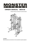
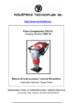
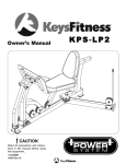
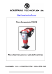
1
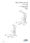
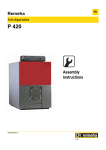
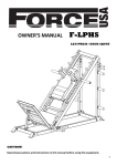
hitch lift
12 vdc, 500 lbs.
Model 47591
assembly and Operating Instructions
Visit our website at: http://www.harborfreight.com
Read this material before using this product.
Failure to do so can result in serious injury.
Save this manual.
Copyright© 2002 by Harbor Freight Tools®. All rights reserved. No portion of this manual or any artwork contained herein may be reproduced in any shape or form without the express written consent of Harbor Freight
Tools. Diagrams within this manual may not be drawn proportionally. Due to continuing improvements, actual
product may differ slightly from the product described herein. Tools required for assembly and service may not
be included.
For technical questions or replacement parts, please call 1-800-444-3353.
iteM
Specifications
descriptiOn
Power Requirement
12 VDC, 45 amps
Power Cable
#45 AWG copper cable with plug; 21 feet long
Control Cable
1/4 inch diameter; 4 feet long; Squeeze trigger
Lift Capacity
500 lbs. (maximum)
Deck Size
25 x 28 inches
Overall Dimensions
15 (H) x 63 (L) inches
Features
- Automatic shutoff
- Non-slip, diamond plate lift surface
Weight
140 lbs.
Note: Customer may need to supply one 50 amp circuit breaker and two 6 AWG battery
terminals with 5/16” stud opening.
Save This Manual
You will need the manual for the safety warnings and precautions, assembly instructions,
operating and maintenance procedures, parts list and diagram. Keep your invoice with this
manual. Write the invoice number on the inside of the front cover. Keep the manual and
invoice in a safe and dry place for future reference.
Safety Warnings and Precautions
WARNING: When using tool, basic safety precautions should always be followed to
reduce the risk of personal injury and damage to equipment.
Read all instructions before using this tool!
1.
Keep work area clean. Cluttered areas invite injuries.
2.
Observe work area conditions. Do not use machines or power tools in damp or wet
locations. Don’t expose to rain. Keep work area well lighted. Do not use electrically
powered tools in the presence of flammable gases or liquids.
3.
Keep children away. Children must never be allowed in the work area. Do not let
them handle machines, tools, or extension cords.
4.
Store idle equipment. When not in use, tools must be stored in a dry location to
inhibit rust. Always lock up tools and keep out of reach of children.
5.
Use the right tool for the job. Do not attempt to force a small tool or attachment to
do the work of a larger industrial tool. There are certain applications for which this
tool was designed. It will do the job better and more safely at the rate for which it was
intended. Do not modify this tool and do not use this tool for a purpose for which it
was not intended.
6.
Dress properly. Do not wear loose clothing or jewelry as they can be caught in
moving parts. Protective, electrically non-conductive clothes and non-skid footwear
are recommended when working. Wear restrictive hair covering to contain long hair.
7.
Use eye protection. Always wear ANSI approved impact safety goggles.
SKU 47591
Page 2
REV 08/02
8.
Do not overreach. Keep proper footing and balance at all times. Do not reach over or
across running machines.
9.
Maintain tools with care. Keep tools sharp and clean for better and safer
performance. Follow instructions for lubricating and changing accessories. Inspect tool
cords periodically and, if damaged, have them repaired by an authorized technician.
The handles must be kept clean, dry, and free from oil and grease at all times.
10. Disconnect power. Unplug Pistol Grip Trigger when not in use.
11. Remove adjusting keys and wrenches. Check that keys and adjusting wrenches
are removed from the hitch before plugging in the Pistol Grip Trigger.
12. Avoid unintentional starting. Be sure the switch is in the Off position when not in
use and before plugging in.
13. Stay alert. Watch what you are doing, use common sense. Do not operate any tool
when you are tired.
14. Check for damaged parts. Before using any tool, any part that appears damaged
should be carefully checked to determine that it will operate properly and perform its
intended function. Check for alignment and binding of moving parts; any broken parts
or mounting fixtures; and any other condition that may affect proper operation. Any
part that is damaged should be properly repaired or replaced by a qualified technician.
Do not use the tool if any Pistol Grip Trigger does not turn On and Off properly.
15. Replacement parts and accessories. When servicing, use only identical
replacement parts. Use of any other parts will void the warranty. Only use accessories
intended for use with this tool. Approved accessories are available from Harbor Freight
Tools.
16. Do not operate tool if under the influence of alcohol or drugs. Read warning
labels on prescriptions to determine if your judgment or reflexes are impaired while
taking drugs. If there is any doubt, do not operate the tool.
17. Maintenance. For your safety, service and maintenance should be performed
regularly by a qualified technician.
18. Pacemaker safety warning. People with pacemakers should consult with their
physician(s) before using this product; operation of equipment in close proximity to a
heart pacemaker could cause interference or failure of the pacemaker.
19. Not to be used for aircraft purposes.
Note: Performance of this tool may vary depending on variations in battery strength.
Warning: The warnings, cautions, and instructions discussed in this instruction manual
cannot cover all possible conditions and situations that may occur. It must be understood by the operator that common sense and caution are factors which cannot be built
into this product, but must be supplied by the operator.
Additional Hitch Lift Safety Precautions
1.
Do not exceed the 500 lbs. rating capacity of the Hitch Lift.
SKU 47591
Page 3
REV 08/02
REV 03/04
2.
Always deploy the Outrigger Assembly Arms when using the Hitch Lift.
3.
Place the load in the center of the lift platform and secure with the Deck Tie-down
Straps.
4.
Make sure the vehicle battery is fully charged before using the Hitch Lift.
5.
Never use to raise or lower people.
6.
Do not move the vehicle with the Deck Plate (19) extended and loaded.
7.
When operating, extend the Pistol Grip Trigger cord, and stay clear of the lift when
raising or lowering load.
8.
Do not allow children to operate the lift.
9.
Only use the Hitch Lift and Motorized Cable Module for its intended purpose.
10. Replace the Lift Cable if it becomes kinked, frayed, or cut.
11. Periodically check all nuts, bolts, and electrical connections for tightness.
12. Periodically clean all Hitch Lift parts of dirt and grime.
13. Never allow slack in the Lift Cable.
14. If a problem occurs with the Hitch Lift loaded, immediately lower the lift to the ground,
and remove power, before attempting to correct the problem.
Unpacking
When unpacking, check to make sure the following parts are included. (Numbered items
refer to the Parts List.) If any parts are missing or broken, please call Harbor Freight Tools
at the number on the cover of this manual as soon as possible.
(10)
(31)
(28)
(15)
(9, 8, 7)
(33)
(34)
(29)
(1, 4)
(2)
(27)
(30)
(18)
(25)
(30)
(20)
(32)
(17) (6, 13, 14)
(24)
(23)
(19)
(32)
Assembly
During assembly it will be necessary to refer to the Assembly Drawing located at the end of
this manual.
SKU 47591
Page 4
REV 08/02
1.
Layout all the parts and components on a large, clean work surface.
2.
Mount the Outrigger Support (29) to the Hitch Adapter Plate (34) using two Bolts (1),
Washers (11), and Lock Nuts (12). See Photo A.
3.
Mount each Outrigger Assembly Arm (28) to the Outrigger Support (29) using Bolt (4),
Washer (11), and Lock Nut (12). See Photo B.
[B]
[A]
(28)
(4)
(9)
(1)
(1)
(12)(11)
(29)
(32)
(12)
(11)
4.
(4)
(29)
(10)
(34)
(28)
(12) (11)
(10)
(33)
(11) (12)
(32)
Mount the Guide Arms (32) to the Pivot Tube (31) at the center using Bolt (7), Washer
(11), and Lock Nut (12). Attach Bolts (10), Washers (11), and Lock Nuts (12) on each
side of the Pivot Tube (31). See Photo C.
[C]
(34)
(33)
(32)
(11) (12)
(31)
(10)
(7)
(11) (12)
5.
(11) (12)
Mount the Lifting Arm (33) to the Pivot Tube (31) using Bolt (9), Washer (11), and Lock
Nut (12).
Caution: Avoid pinching fingers between the Lifting Arm and the Pivot Tube.
6.
Mount the other end of the Lifting Arm (33) to the Hitch Adapter Plate (34) using Bolt
(9), Washer (11), and Lock Nut (12). See Photo C on the previous page.
7.
Mount the other ends of the Guide Arms (32) to the inside of the Outrigger Support
(29) using Bolts (7), Washers (11), and Lock Nuts (12). Use Bolts (10), Washers (11),
and Lock Nuts (12) on the outside of the Outrigger Support (29). See Photo B on the
previous page.
SKU 47591
Page 5
REV 08/02
8.
Insert the Platform Arms (30) over each end of the Pivot Tube (31). Insert the Quick
Release Pins (2) in each side. See Photo D.
[D]
(30)
(30)
(2)
(31)
(2)
9.
Place (and hold) the Deck Plate (19) against the Platform Arms (30) with the Deck
Plate tabs to the right of the Platform Arms. Have someone help you with step.
10. Using Bolts (15), Washers (13), and Lock Nuts (14), secure Deck Plate (19) tabs to
the Platform Arms (30) at four points. Tighten Securely.
11. Mount the Motorized Cable Module (27) to the Hitch Adapter Plate (34) using four Cap
Screws (6), eight Washers (13), and four Lock Nuts (14). See photo E.
Two Washers are used: one under the Cap Screw and one under the Lock Nut.
The Lock Nuts should be placed on the outside of the Hitch Adapter Plate. Tighten
securely with the Allen Wrench (17). The weight of the Motorized Cable Module may
require someone to help you hold it while you place the mounting hardware.
[E]
(6) - Typical of four
(not shown)
Motorized Cable Module (27)
(34)
(13, 14) - Typical of four
Limit Switch Cover
12. Mount the Lift Hitch to the vehicle receiver hitch.
Because of the weight of the assembled Lift Hitch, have someone help you lift it onto
the receiver hitch. Insert a 1/2 inch high grade steel hitch pin (not supplied) through
the holes in the Hitch Adapter Plate (34) and the vehicle receiver hitch. Attach the
Stabilizer Clamp (18) to the Hitch Adapter Plate (34). Lower the Outrigger Assembly
Arms (28) so they are near the ground, but not touching. Then, turn its lower shaft so
that the foot pad touches the ground. Carefully lower the Deck Plate to the ground.
SKU 47591
Page 6
REV 08/02
13. Disconnect the positive (red) cable to the vehicle battery.
You will now be making an electrical connection from the Motorized Cable Module
(27) to the vehicle electrical system.
Caution: Although the 12 VDC battery cannot shock you, it can spark and heat up cables
to the melting point, and can cause burns, if not installed and fused correctly. That is
why the battery is disconnected at this time.
14.
Locate an appropriate positive (+ / red), fused, 50 amp terminal point on the vehicle able to supply the 45 amps of current the lift will be drawing at full load.
If vehicle is already wired with a rear, 12 volt connector, the lift may be connected here with the appropraite connector ( not supplied). The circuit MUST BE ABLE TO HANDLE the Hitch Lift’s 45 amp draw and must be fused at 50 amps. YOU SHOULD CHECK your vehicle’s owner’s manual or consult with the auto dealer to ensure that the vehicle’s electrical circuit is capable of handling this kind of current load.
If no fused, 50 amp terminal point is provided, you will need to provide a separate
circuit (fused at 50 amps) directly from the battery. The customer will need to provide one (1) 50 amp circuit breaker and two (2) 6 AWG battery terminals with 5/16”
opening.
15.
Route the cables, making sure that you leave enough cable to plug the connector into the Motorized Cable Module (#27). Also route cable away from any hot spots (muffler, catalytic converter) or any area where the cable may be pinched or cut.
16.
If vehicle has an existing spare 50 amp fused terminal point, simply connect the
supplied positive cable directly to the fused terminal point.
17.
If the vehicle as no 50 amp terminal point, the customer will need to install a 50 amp circuit breaker (not included) in line between the battery and Hitch Lift. The circuit breaker should be installed as close to the battery as possible. The RED cable will need to be cut and the two 6 AWG battery terminals installed into the ends of the cable. The short end of the cut cable should be long enough to reach the battery terminal. Connect one end of the cable to a circuit breaker post. Now connect the other cable end to the other post.
AT THIS TIME, DO NOT CONNECT THE CABLE TO THE BATTERY!!
18. Connect the black negative (-) cable to the vehicle’s metal frame, or a ground lug on
or near the battery.
19. Reconnect the red positive (+) battery cable to the battery.
20. Plug the Lift Hitch Battery Cable (23) connector plug into the Motorized Cable Module.
It is located under the module. See photo F.
21. Plug the Pistol Grip Trigger (24) cable plug into the Motorized Cable Module.
SKU 47591
Page 7
REV 08/02
[G]
[F]
(22)
(24)
(13)
(14)
(8)
(23)
22. Unroll the Lift Cable (22) from the Cable Drum (21) by pressing the Pistol Grip Trigger.
The lever above the trigger can be pressed left or right to wind up or unwind the cable.
Press the Pistol Grip Trigger momentarily to see the direction of the Cable Drum. If it
is not unwinding, press the lever above the trigger in the opposite direction. As cable
unwinds, hold the cable end until it reaches the tab on the Lifting Arm (33). See photo
G on the previous page.
23. Attach the Lift Cable (22) to the Lifting Arm (33) tab using Bolt (8), Washer (13), and
Lock Nut (14). Tighten securely.
24. Press the Pistol Grip Trigger to raise the Deck Plate to its upper position until it stops.
The cable should wind up uniformly.
25. Check the upper most height of the Deck Plate, then its lowest point. If it does not stop
at the desired height, adjustment of the Limit Switches is necessary.
Limit Switch Adjustments
1.
Using a Phillips screwdriver, remove the screws holding the Limit Switch Cover to the
Motorized Cable Module (27). Remove the Cover Plate. See photos E and H.
2.
Loosen the Adjuster Locking Nut, but do not remove.
3.
Reposition each cam as follows:
- To change the lower limits, turn the White Adjusters clockwise to lower the stopping
point, or counterclockwise to raise the stopping point.
- To change the upper limits, turn the Black Adjusters clockwise to lower the stopping
point, or counterclockwise to raise the stopping point.
- Retighten the Adjuster Locking Nut.
4.
Test the upper and lower level stops using the Pistol Grip Trigger.
If more adjustment is necessary, repeat steps 2, 3, and 4.
5.
Another method to set the upper level adjustments is to lower the vehicle tailgate, if
equipped, and slowly raise the Deck Plate until it is level with the tailgate. Loosen
the Adjuster Locking Nut and turn the Black Upper Limit adjuster Screw to rotate the
upper limit cam in a clockwise direction until the Upper Limit Switch Arm is depressed.
The Deck Plate should not go any higher. Retighten the Adjuster Locking Nut.
SKU 47591
Page 8
REV 08/02
To change the lower limits in a similar manner, lower the Deck Plate until it just
touches the ground. With the Adjuster Locking Nut loose, turn the White Lower Limit
Screw to rotate the lower limit cam in a counterclockwise direction until the Lower
Limit Switch Arm starts to move, and is depressed. Retighten the Adjuster Locking
Nut.
Note: Do not activate the switch arms at the same time or the Deck Plate will not move in
either direction.
6.
Replace the screws holding the Limit Switch Cover Plate to the Motorized Cable
Module (27).
[H]
Motorized Cable Module (27)
Lower Limit Cam (White)
Upper Limit Cam (Black)
Upper Adjuster (Black)
Lower Limit Switch Arm
Adjuster Locking Nut
Upper Limit Switch Arm
Lower Adjuster (White)
Operation
Raising a Load
1.
Remove the Quick Release Pin (2) from each Outrigger Assembly Arm, and turn each
Arm so that it is vertical, and a few inches above the ground. See photos J.
2.
Lower the vehicle tailgate, if equipped.
3.
Center and secure the load (500 lbs. max.) to the Deck Plate using the Deck Tie-down
Straps (20).
4.
Place the Pistol Grip Trigger lever to the UP position, then squeeze the trigger until the
Deck Plate is just above the ground.
5.
Stop, and turn each Outrigger Assembly Arm foot until it rests on the ground.
6.
Continue to raise the Deck Plate until the upper limit is reached.
7.
Remove the straps and transfer the load to the vehicle. Secure the load in the vehicle.
8.
Lower the Deck Plate until it is a few inches above the ground.
9.
Remove the retaining clips and Quick Release Pins.
SKU 47591
Page 9
REV 08/02
10. Push the Deck Plate up to its storage position, and replace the Quick Release Pins.
11. Raise the Lift Hitch to its uppermost position.
12. Raise each Outrigger Assembly Arm foot by turning it. A wrench may be required.
13. Remove the Quick Release Pins and turn each Outrigger Assembly Arm to the
horizontal position. Replace the Quick Release Pins.
14. Unplug the Pistol Grip Trigger cable and store in a secure location.
[J]
Lowering a Load
1.
Remove the Quick Release Pin (2) from each Outrigger Assembly Arm, and turn each
Arm so that it is vertical, and a few inches above the ground.
2.
Plug in the Pistol Grip Trigger (24).
3.
Lower the vehicle tailgate, if equipped.
Caution: Take care that the Deck Plate does not fall on you when the Quick Release
Pins and clips are removed.
4.
Remove the Quick Release Pins and clips, and lay the Deck Plate flat. Replace the
Pins and clips.
5.
Using the Pistol Grip Trigger, raise the Deck Plate to its uppermost position.
6.
Carefully transfer the load to the Deck Plate and secure with the Deck Tie-down
Straps.
7.
Turn each Outrigger Assembly Arm foot until it rests on the ground.
8.
Using the Pistol Grip Trigger, lower the load to the ground.
9.
Remove the straps, then the load.
10. Using the Pistol Grip Trigger, raise the Deck Plate a few inches above the ground.
11. Remove the Quick Release Pins and clips and raise the Deck Plate to its storage
position. Replace the Pins and clips.
12. Using the Pistol Grip Trigger, raise the Deck Plate to its upper limit.
13. Raise each Outrigger Assembly Arm foot by turning it. A wrench may be required.
13. Remove the Quick Release Pins and turn each Outrigger Assembly Arm to the
horizontal position. Replace the Quick Release Pins.
14. Unplug the Pistol Grip Trigger cable and store in a secure location.
SKU 47591
Page 10
REV 08/02
Maintenance
1.
Before each use, check for any Hitch Lift damage, loose hardware, crimped cable,
bent components. If any are found, do not use until properly repaired by a qualified
technician.
2.
Periodically clean all components with a mild soap and water.
3.
Periodically lubricate moving joints with a light oil.
Replacing the Lift Cable
1.
Using a Phillips screwdriver, remove the screws holding the Limit Switch Cover Plate
to the Motorized Cable Module (27). Remove the Cover Plate.
2.
Using the Pistol Grip Trigger, lower the Deck Plate to the ground.
3.
Loosen the Adjuster Locking Nut. While pulling on the cable, move the Lower Limit
Cam (white) so that all the cable can be unwound.
4.
Using an Allen Wrench, remove the two set screws (S) located on the cable drum
(above the cable holes). Pull the cable end out of the hole. See photo K.
5.
Remove the other end of the cable from the Lifting Arm (33).
6.
Unwind the new cable (22) and push the end through the
holes in the cable drum. See Assembly Drawing, Item # 3.
The cable end should not protrude out of the second hole,
but just meet the cable drum surface. Screw in the two new
set screws that came with the new cable. Securely tighten.
7.
Using the Pistol Grip Trigger, rewind the new cable onto the
cable drum so that each turn is side-by-side.
Keep tension on the cable while rewinding. Leave enough
cable out to connect the other end to the Lifting Arm (33).
It may be necessary to adjust the Upper Limit Cam (black)
while rewinding.
8.
Adjust the Upper and Lower Limit Cams as described on page 8.
9.
Replace the Limit Switch Cover Plate and Screws.
[K]
(S)
(22)
PLEASE READ THE FOLLOWING CAREFULLY
THE MANUFACTURER AND/OR DISTRIBUTOR HAS PROVIDED THE PARTS DIAGRAM IN THIS
MANUAL AS A REFERENCE TOOL ONLY. NEITHER THE MANUFACTURER NOR DISTRIBUTOR
MAKES ANY REPRESENTATION OR WARRANTY OF ANY KIND TO THE BUYER THAT HE
OR SHE IS QUALIFIED TO MAKE ANY REPAIRS TO THE PRODUCT OR THAT HE OR SHE IS
QUALIFIED TO REPLACE ANY PARTS OF THE PRODUCT. IN FACT, THE MANUFACTURER
AND/OR DISTRIBUTOR EXPRESSLY STATES THAT ALL REPAIRS AND PARTS REPLACEMENTS
SHOULD BE UNDERTAKEN BY CERTIFIED AND LICENSED TECHNICIANS AND NOT BY THE
BUYER. THE BUYER ASSUMES ALL RISK AND LIABILITY ARISING OUT OF HIS OR HER
REPAIRS TO THE ORIGINAL PRODUCT OR REPLACEMENT PARTS THERETO, OR ARISING
OUT OF HIS OR HER INSTALLATION OF REPLACEMENT PARTS THERETO.
SKU 47591
Page 11
item #
Parts List
description
Qty
1
Bolt, M12x80
2
2
Quick Release Pin, 012
4
3
Screw Set, M5x10
2
4
Bolt, M12x75
2
5
Bolt, M10x30
2
6
Screw, Hex Head, M10x40
4
7
Bolt, M12x105
2
8
Bolt, M10x35
1
9
Bolt, M12x85
2
10
Bolt, M12x35
4
11
Washer, M12
12
12
Nut, Nylon Lock, M12
12
13
Washer, M10
13
14
Nut, Nylon Lock, M10
9
15
Bolt, M10x55
4
16
Plastic Cap, Hitch
1
17
Wrench, Allen, M10
1
18
Clamp, Stabilizer
1
19
Deck Plate
1
20
Tie-down Straps, Deck
2
21
Cable Drum, Motorized
1
22
Lift Cable
1
23
Cable, Battery
1
24
Pistol Grip Trigger w/ cable
1
25
Wrench, Outrigger
1
26
Rubber Pad, Hitch
1
27
Cable Module, Motorized
1
28
Outrigger Assembly Arm
2
29
Outrigger Support
1
30
Arm, Platform
2
31
Tube, Pivot
1
32
Arms, Guide
2
33
Arm, Lifting
1
34
Plate, Hitch Adapter
1
Assembly Drawing
NOTE: Some parts are listed and shown for illustration purposes only and are not available
individually as replacement parts.
SKU 47591
Page 12
Assembly Drawing
SKU 47591
Page 13
Winch Assembly Drawing
SKU 47591
SKU 47591
Page 14
Page 14
REV 06/05
Winch Parts List
PARTPART
NO.DESCRIPTION
Q’TYNO.DESCRIPTION
Q’TY
W1
MOTOR COVER ASS’Y
1
W22
M6*10 BOLT
3
W2
M5*12 BOLT
4
W23
GEAR CONNECTOR
1
W3
M6*135 BOLT
2
W24
SPRING
1
W4
M6 LOCK WASHER
2
W25
BEARING
2
W5
MOTOR 12V DC
1
W26
CABLE PROTECTOR
2
W6
BEARING
1
W27
M5*10 SCREW
2
W7
SPRING PIN d3*12
1
W28
DRUM
1
W8
GEAR HOUSING
1
W29
AIR CRAFT CABLE
1
W9
BEARING HK2014
1
W30
BEARING
1
W10
GEAR 1
W31
COVER
1
W11
INNER GEAR
1
W32
M8*23 BOLT
4
W12
STOP PIN
1
W33
B4*20 PIN
4
W13
GEAR RING
1
W34
BASE
1
W14
PLANETARY GEAR FRAME 2
W35
AUTO LIMIT SWITCH ASS’Y
1
W15
PLANETARY DEAR
3
W36
M5 LOCK WASHER
4
W16
BEARING
3
W37
M5*14 BOLT
4
W17
PLANETARY PIN
3
W38
COVER
1
W18
GEAR RING
1
W39
M5*12 BOLT
4
W19
DIVE PLATE
1
W40
CABLE TENSION PLATE
1
W20
THRUST RING
1
W41
M6 LOCK WASHER
4
W21
DRUM SUPPORT
1
W42
M6*12 BOLT
4
SKU 47591
Page 15
REV 06/05