1
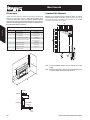
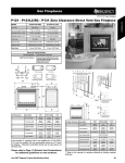
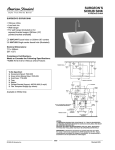
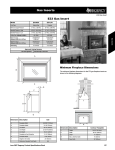
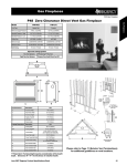
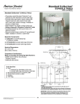
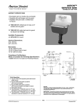
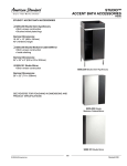
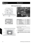
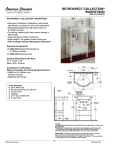
Gas Inserts
U32 Regency Gas Insert
U32 Regency Gas Insert
Model
U32-NG5
U32-LP5
Fuel Type
Natural Gas
Propane
5” W.C. (1.25 kPa)
12” W.C. (2.99 kPa)
Minimum Supply Pressure
Manifold Pressure - High
3.8” W.C. (0.95 kPa)
11” W.C. (2.74 kPa)
Manifold Pressure - Low
1.1” W.C. (0.27 kPa)
2.9” W.C. (0.72 kPa)
Orifice Size -Altitude 0-4500 ft.
#52 DMS
15,300 BTU/h
(4.48 kW)
15,000 BTU/h
(4.40 kW)
Maximum Input
Altitude 0-4500 ft. (0-1372m)
30,000 BTU/h
(8.79 kW)
30,000 BTU/h
(8.79 kW)
3” Co-linear
3” Co-linear
Vent Sizing
Gas Inserts
#37 DMS
Minimum Input
Altitude 0-4500 ft. (0-1372m)
Approved Venting Systems
Flex Vent Systems:
FPI AstroCap™ Flex Vent
A
Minimum Fireplace Dimensions
The minimum fireplace dimensions for the FPI gas fireplace insert are
shown in the following diagrams:
B
aaaaa
aaaaa
aaaaa
aaaaa
aaaaa
aaaaa
aaaaa
aaaaa
aaaaa
aaaaa
aaaaa
aaaaa
C
G
F
I
M
L
J
H D
aaaaaaaaaa
aaaaaaaaaa
aaaaaaaaaa
K
aaaaaaaaaa
aaaaaaaaaa
aaaaaaaaaa
aaaaaaaaaa
E
Dimension Description
U32
A
Faceplate Width
40-1/4” (1022mm)
B
Faceplate Height
26-1/4” (667mm)
C
Unit Width
28” (711mm)
D
Unit Height
20” (508mm)
E
Unit Depth
13-3/4” (349mm)
J
F
Faceplate to Vent Centerline
10-3/4” (273mm)
K
G
Faceplate Depth
1-3/8” (35mm)
L
H
Height to Vent Collar
21-1/16” (535mm)
M
Max. Lintel Bar Depth
I
Optional or Standard Front Depth
3-3/4” (95mm)
N
Rear Width
August 2008 Product Specifications Book
aaaaa
aaaaa
aaaaa
aaaaa
aaaaa
aaaaa
aaaaa
aaaaa
aaaaa
aaaaa
aaaaa
aaaaa
aaaaa
aaaaa
aaaaa
aaaaa
aaaaa
aaaaa
aaaaa
aaaaa
aaaaa
aaaaa
aaaaa
aaaaa
aaaaa
N
Contour
Faceplate
Molded
Faceplate
Height
22” (559mm)
22” (559mm)
Width
26-1/2” (673mm)
29” (737mm)
Depth
14” (356mm)
15” (381mm)
Dimension Description
9” (229mm)
10” (254mm)
22-1/2” (572mm)
22-1/2” (572mm)
125
Gas Inserts
U32 Regency Gas Insert
Clearances
Combustible Mantels
Unless otherwise stated the clearances listed below are Minimum
distances to combustible materials. Please Note: A major cause
of chimney related fires is due to a failure to maintain required
clearances (air space) to combustible materials. It is of the greatest
importance that this fireplace and vent system be installed only in
accordance with these instructions.
Because of the extreme heat this fireplace emits, the mantel
clearances are critical. Combustible mantel clearances from top of
the louvers are shown in the diagram below. Mantel may be installed
anywhere in the shaded area or higher.
Gas Inserts
Clearances to Combustibles
Dimension
Description
A
From Unit to Sides
U32
10” (254mm)
B
From Unit to Ceiling
47.5” (1207mm)
C
From Unit to Mantel
see diagram 2 & 3
D
From Standard Surround to Sides
4” (102mm)
E
From Standard Surround to Ceiling
41.5” (1054mm)
also see diagram 2 & 3
G
Maximum Mantel Depth
12” (305mm)
see diagram 2
H
Minimum Alcove Width
48” (1219mm)
I
Maximum Alcove Depth
36” (914mm)
*
No Hearth Required
B
E
G
I
Note: A non-combustible mantel may be installed at a lower
height.
Note: Ensure the paint that is used on the mantel and the facing
is “heat resistant” or the paint may discolour.
C
A
H
D
Mantle
12" Max.
G
C
Faceplate
Combustible
Flooring
Flush
with
Floor
126
August 2008 Product Specifications Book