1
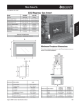
Gas Inserts
E33 Gas Insert
E33 Gas Insert
Model
E33-NG1
E33-LP1
Fuel Type
Natural Gas
Propane
5” W.C. (1.25 kPa)
12” W.C. (2.99 kPa)
Minimum Supply Pressure
Manifold Pressure - High
3.8” W.C. (0.95 kPa)
11” W.C. (2.74 kPa)
Manifold Pressure - Low
1.1” W.C. (0.27 kPa)
2.9” W.C. (0.72 kPa)
Orifice Size -Altitude 0-4500 ft.
#50 DMS
20,000 BTU/h
(5.86 kW)
19,000 BTU/h
(5.57 kW)
Maximum Input
Altitude 0-4500 ft. (0-1372m)
38,000 BTU/h
(11.14 kW)
35,500 BTU/h
(10.40 kW)
3” Co-linear
3” Co-linear
Vent Sizing
Gas Inserts
#31 DMS
Minimum Input
Altitude 0-4500 ft. (0-1372m)
Approved Venting Systems
Flex Vent Systems:
FPI AstroCap™ Flex Vent
A
Minimum Fireplace Dimensions
B
The minimum fireplace dimensions for the FPI gas fireplace insert are
shown in the following diagrams:
aaaaa
aaaaa
aaaaa
aaaaa
aaaaa
aaaaa
aaaaa
aaaaa
aaaaa
aaaaa
aaaaa
aaaaa
C
G
F
30°
M
L
J
D H
aaaaaaaaaa
aaaaaaaaaa
aaaaaaaaaa
K
aaaaaaaaaa
aaaaaaaaaa
aaaaaaaaaa
aaaaaaaaaa
E
Dimension Description
E33
A
Faceplate Width
45-9/16” (1157mm)
B
Faceplate Height
31-1/8” (791mm)
C
Unit Width
32-1/4” (819mm)
D
Unit Height
23-13/16” (605mm)
E
Unit Depth
F
Faceplate to Vent Centerline
G
Faceplate Depth
H
Height to Vent Collar
I
Optional or Standard Front Depth
aaaaa
aaaaa
aaaaa
aaaaa
aaaaa
aaaaa
aaaaa
aaaaa
aaaaa
aaaaa
aaaaa
aaaaa
aaaaa
aaaaa
aaaaa
aaaaa
aaaaa
aaaaa
aaaaa
aaaaa
aaaaa
aaaaa
aaaaa
aaaaa
aaaaa
N
Dimension Description
Contour Faceplate
J
Height
24-3/16” (614mm)
16-3/4” (426mm)
K
Width
32-1/4” (819mm)
11-1/4” (286mm)
L
Depth
17” (432mm)
1-3/8” (35mm)
M
Max. Lintel Bar Depth
8” (203mm)
23” (583mm)
N
Rear Width
25” (635mm)
June 2007 Regency Product Specifications Book
N/A
127
Gas Inserts
E33 Gas Insert
Clearances
Combustible Mantels
Unless otherwise stated the clearances listed below are Minimum
distances to combustible materials. Please Note: A major cause
of chimney related fires is due to a failure to maintain required
clearances (air space) to combustible materials. It is of the greatest
importance that this fireplace and vent system be installed only in
accordance with these instructions.
Because of the extreme heat this fireplace emits, the mantel
clearances are critical. Combustible mantel clearances from top of
the louvers are shown in the diagram below. Mantel may be installed
anywhere in the shaded area or higher.
Dimension
Description
A*
From Unit to Side Walls
E33
B
From Unit to Ceiling
47” (1194mm)
C
Minimum Mantel Height
15” (381mm)
D
Maximum Mantel Depth
12” (305mm)
E
Alcove Width
76” (1930mm)
F
Alcove Depth
36” (914mm)
G
Hearth Height
1-¼” (32mm)
H
Hearth Width
45-½” (1156mm)
I
Hearth Depth
13” (330mm)
8” (203mm)
* Alcove side wall must have a minimum of 8” (203mm) clearance on one side.
Flush Front Mantel Clearances
12
20
10
8
6
4
0
Gas Inserts
Clearances to Combustibles
2
12" (305mm) Mantel
18
16
14
47”
(1194mm)
to ceiling 12
10
3-1/2" (89mm) Mantel
20”
(508mm)
15”
(381mm)
8
6
4
D
2
0
25" (635mm)
to floor
Top of
Unit
Side View
Full Screen Door Mantel Clearances
Note: A non-combustible mantel may be installed at a lower
height.
Note: Ensure the paint that is used on the mantel and the facing
is “heat resistant” or the paint may discolour.
128
June 2007 Regency Product Specifications Book