1
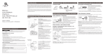
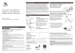
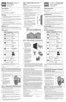
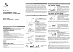
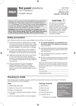
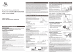
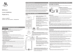
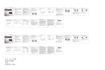
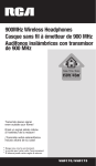
4-Source Audio/Video Switcher
with Remote Control
VH915N User's Manual
Voltee el libro para instrucciones en español
Installation
This switcher lets you manage up to four video sources through one video input on
your TV. The back panel of the switcher has four inputs and one output. Connect the
switcher to your TV first.
Important: Use either composite video (the yellow jacks) or S-Video on all of your
connections. If all of your components (including your TV) offer S-Video connections,
use all S-Video connections. Otherwise, use all composite video connections.
Connecting to your TV
OR
TELEVISION
AUDIO IN 1 VIDEO
DC 9V L
200mA
AUDIO IN 2 VIDEO
L
AUDIO IN 3 VIDEO
L
AUDIO IN 4 VIDEO
L
AUDIO OUT VIDEO
1. Make the video connection.
Connect EITHER an S-Video cable or
a composite video cable to the corresponding OUT VIDEO jack on the
switcher's back panel. Connect the
other end of the cable to the TV's video
input jack.
L
2. Make the audio connection.
Connect a stereo audio cable to the
OUT AUDIO R and L jacks on the
switcher's back panel. Connect the
other end of the cable to your TV's
audio input jacks.
Make sure you match the color coding at the end of the cables with the color coding on the jacks—match red with red and white with white.
R
R
S
R
S
R
S
R
S
S
Safety Information
Caution: To reduce the risk of electric shock, do not remove cover (or back). No user serviceable parts inside.
Refer servicing to qualified service personnel.
Warning: To reduce the risk of fire or electric shock, do not expose this product to rain or moisture. The
apparatus shall not be exposed to dripping or splashing. No objects filled with liquids, such as vases, shall be
placed on the apparatus.
This symbol indicates "dangerous voltage"
inside the product that presents a risk of
electric shock or personal injury.
This symbol indicates important instructions
accompanying the product.
Product Information
Keep your sales receipt to obtain warranty parts and service and for proof of purchase. Attach it here and record
the model number in case you need it. This number is located on the product.
Model Number: ______________________________Purchase Date: ____________________________
Dealer/Address/Phone: ________________________________
Connecting to your input components
AUDIO IN 1 VIDEO
DC 9V L
200mA
AUDIO IN 2 VIDEO
L
R
R
DBS
R
S
S
OR
DVD
AUDIO OUT VIDEO
L
R
S
OR
AUDIO IN 4 VIDEO
L
R
S
OR
AUDIO IN 3 VIDEO
L
S
OR
VCR
VIDEO
GAME
(Audio/Video
or
S-Video
hook-up
only)
CAMCORDER
1. Make the video connection.
For the first component, connect EITHER an S-Video cable or a composite video
cable to the corresponding IN1 VIDEO jack on the switcher's back panel.
Connect the other end of the cable to the component's video output jack.
2. Make the audio connection.
For the first component, connect a stereo audio cable to the IN1 AUDIO jacks on
the switcher's back panel.
Connect the other end of the cable to the component's audio output jacks.
Make sure you match the color coding at the end of the cables with the color
coding on the jacks—match red with red and white with white.
3. Repeat the video and audio connection steps for your other input components on
IN2, IN3 and IN4.
As you connect your components to the input jacks, note which component you
have connected to each jack in the space provided below. This information is
important to have handy.
Reference Chart
INPUT 1 INPUT 2
INPUT 3 INPUT 4
Note which component you connect to each input.
2
Installing batteries in your remote
Your remote requires two AAA alkaline batteries (sold separately).
To install the batteries:
1. Remove the battery compartment cover.
2. Insert the batteries, matching the (+) and (–) marks inside the battery
compartment.
3. Push the battery cover back into place.
Battery Precautions:
• Do not mix old and new batteries.
• Do not mix alkaline, standard (carbon-zinc) or rechargeable (nickel-cadmium)
batteries.
• Always remove old, weak or worn-out batteries promptly and recycle or dispose of
them in accordance with Local and National Regulations.
Connecting to a power source
Connect the supplied power adapter to the DC9V jack on the back of the switcher.
Plug the other end of the power adapter into a wall outlet or surge protector.
Important: This power unit is intended to be correctly oriented in a vertical or floor
mount position.
Using the switcher
Once you've installed the switcher, you're ready to start using it.
Getting Started
• Make sure your TV and components are turned on.
• Make sure you're watching the correct input on the TV—for example, if you've
connected the switcher to the VID input on your TV, you need to "tune" to this
input in order to see the switcher on the TV screen.
To turn the switcher on: Press the POWER key on the remote control or on the
switcher's front panel. The switcher's display panel should light up.
To switch between inputs: Press the SELECT key on the remote control or on the
switcher's front panel. The switcher's display panel changes numbers and your TV
should show the corresponding signal.
To go to a specific input: Press one of the number keys on the remote. The switcher
display panel changes to that number and your TV screen should display the signal
from that input.
3
Using the Scan function
This switcher also offers an automatic scanning function, which automatically cycles
through the inputs at an interval you set. The scan function is ideal for use with security
cameras or other home monitoring devices.
To activate the scan function: Press the SCAN key on the remote control or on the
switcher's front panel. The switcher starts scanning through the input automatically
after 2-3 seconds.
To deactivate the scan function: Press the one of the input number keys or the SELECT
key on the remote.
To increase the scanning interval: Press the SCAN key. Each press increases the
interval—use the following chart as a guide.
Press
1st
2nd
3rd
4th
5th
6th
7th
8th
Interval
2.5 seconds
5 seconds
7.5 seconds
10 seconds
12.5 seconds
15 seconds
17.5 seconds
20 seconds
Troubleshooting
Most difficulties you encounter with the switcher can be fixed by trying one of the
following solutions.
Problem: Switcher won't turn on.
• Make sure the power adapter is properly connected to the switcher and plugged
into the wall.
Problem: No video/audio from the TV.
• Make sure your TV is turned on.
• Make sure the switcher is turned on.
• Make sure the device connected to the input you want to see is turned on and
transmitting a signal. For example, if you want to watch your DVD player, make sure
the DVD player is on and that a DVD is playing.
• Make sure all video and audio cables are firmly inserted in the correct inputs and
outputs on the switcher and on the components.
4
• Make sure the video and audio cables work. Test them by connecting them directly
to the TV.
Problem: Wrong video/audio signal on the TV.
• Make sure you have the correct input selected on the switcher.
• Make sure the TV is tuned to the correct input to display the signal coming from the
switcher. For example, if you connected the switcher to the input labeled VID on
your TV, make sure this is the input you've selected to display on the TV screen.
• Check the cables on the back of the switcher to make sure you have them in the
right place—for example, if you think your DVD player is plugged into input 3,
confirm that the cables from DVD player are connected to the video and audio input
jacks marked IN3 on the back of the switcher.
• Make sure the device connected to the input you want to see is turned on and
transmitting a signal. For example, if you want to watch your DVD player, make sure
the DVD player is on and that a DVD is playing.
Problem: Remote won't select/switch inputs.
• Make sure the switcher is turned on.
• Make sure there's a clear path between the remote and the switcher's front panel.
• Make sure you're pointing the remote directly at the switcher's front panel.
• Replace the remote control's batteries.
5
12 Month Limited Warranty
Audiovox Electronics Corporation (the “Company”) warrants to the original retail purchaser of this product that
should this product or any part thereof, under normal use and conditions, be proven defective in material or
workmanship within 12 months from the date of original purchase, such defect(s) will be repaired or replaced (at the
Company’s option) without charge for parts and repair labor. To obtain repair or replacement within the terms of this
Warranty, the product along with any accessories included in the original packaging is to be delivered with proof of
warranty coverage (e.g. dated bill of sale), specification of defect(s), transportation prepaid, to the Company at the
address shown below. Do not return this product to the Retailer.
This Warranty is not transferable and does not cover product purchased, serviced or used outside the United
States or Canada. The Warranty does not extend to the elimination of externally generated static or noise. This
Warranty does not apply to costs incurred for installation, removal or reinstallation of the product, or, if in the
Company’s opinion, the product has been damaged through acts of nature, alteration, improper installation,
mishandling, misuse, neglect, accident, or the simultaneous use of different battery types (e.g. alkaline, standard or
rechargeable). This Warranty does not cover damage caused by an AC adapter not provided with the product.
THE EXTENT OF THE COMPANY’S LIABILITY UNDER THIS WARRANTY IS LIMITED TO THE REPAIR OR
REPLACEMENT PROVIDED ABOVE AND, IN NO EVENT, SHALL THE COMPANY’S LIABILITY EXCEED THE PURCHASE
PRICE PAID BY PURCHASER FOR THE PRODUCT.
This Warranty is in lieu of all other express warranties or liabilities. ANY IMPLIED WARRANTIES, INCLUDING ANY
IMPLIED WARRANTY OF MERCHANTABILITY OR FITNESS FOR A PARTICULAR PURPOSE, SHALL BE LIMITED TO
DURATION OF THIS WARRANTY. ANY ACTION FOR BREACH OF ANY WARRANTY HEREUNDER, INCLUDING ANY
IMPLIED WARRANTY, MUST BE BROUGHT WITHIN A PERIOD OF 24 MONTHS FROM THE DATE OF ORIGINAL
PURCHASE. IN NO CASE SHALL THE COMPANY BE LIABLE FOR ANY CONSEQUENTIAL OR INCIDENTAL DAMAGES
WHATSOEVER. No person or representative is authorized to assume for the Company any liability other than
expressed herein in connection with the sale of this product.
Some states/provinces do not allow limitations on how long an implied warranty lasts or the exclusion or
limitation of incidental or consequential damage so the above limitations or exclusions may not apply to you. This
Warranty gives you specific legal rights and you may also have other rights which vary from state/province to
state/province.
U.S.A.: Audiovox Electronics Corporation, 150 Marcus Blvd., Hauppauge, New York 11788
CANADA: Audiovox Return Center, c/o Genco, 6685 Kennedy Road, Unit 3, Door 16, Mississauga, Ontario L5T 3A5
©2008 Audiovox Accessories Corporation
111 Congressional Blvd., Suite 350
Carmel, IN 46032
Trademark(s) Registered®
Made in China
VH915N US IB 00
Garantía Limitada de 12 Meses
Audiovox Electronics Corporation (la “Compañía”) le garantiza a usted, el comprador original de este producto que si,
bajo condiciones y uso normales, se encontrara que este producto o alguna pieza presenta defectos materiales o de
mano de obra dentro de los primeros 12 meses a partir de la fecha de compra original, tales defectos serán reparados
o reemplazados (a opción de la Compañía) sin cargo alguno por las piezas y labores de reparación. Para obtener
los servicios de reparación o reemplazo dentro de los términos de esta Garantía, el producto junto con cualquier
accesorio incluido en el empaque original se entregarán con prueba de cubierta de garantía (por ejemplo, factura
fechada de venta), especificación de los defectos, transporte prepagado, a la Compañía a la dirección indicada abajo.
No devuelva este producto al Distribuidor.
Esta Garantía no es transferible y no cubre un producto adquirido, mantenido o utilizado fuera de los Estados Unidos o
Canadá. Esta Garantía no incluye la eliminación de estática o ruido generados externamente. Esta Garantía no incluye
los costos incurridos en la instalación, remoción o reinstalación de este producto, o, si es opinión de la Compañía, que
este producto ha sufrido daños debido a causas de fuerza mayor, alteraciones, instalación inadecuada, abuso, uso
indebido, negligencia, accidente, o el uso simultáneo de diferentes tipos de baterías (por ejemplo, alcalinas, típicas
o recargables). Esta Garantía no incluye daños ocasionados por un adaptador de CA que no haya sido suministrado
con el producto.
EL ALCANCE DE LA RESPONSABILIDAD DE LA COMPAÑÍA BAJO ESTA GARANTÍA ESTÁ LIMITADO A LA
REPARACIÓN O EL REEMPLAZO PROVISTO ARRIBA Y, EN NINGÚN CASO, DEBERÁ LA RESPONSABILIDAD DE LA
COMPAÑÍA EXCEDER EL PRECIO DE COMPRA PAGADO POR EL COMPRADOR DE ESTE PRODUCTO.
Esta Garantía reemplaza cualesquiera otras responsabilidades o garantías expresas. CUALESQUIERA GARANTÍAS
IMPLÍCITAS, INCLUYENDO CUALQUIER GARANTÍA IMPLÍCITA DE COMERCIABILIDAD O ADAPTABILIDAD PARA
UN PROPÓSITO EN PARTICULAR ESTARÁN LIMITADAS A LA DURACIÓN DE ESTA GARANTÍA. CUALQUIER ACCIÓN
PARA EL INCUMPLIMIENTO DE CUALQUIER GARANTÍA EN EL PRESENTE, INCLUYENDO CUALQUIER GARANTÍA
IMPLÍCITA, DEBERÁ PRESENTARSE DENTRO DE UN PERÍODO DE 24 MESES A PARTIR DE LA FECHA DE COMPRA
ORIGINAL. EN NINGÚN CASO LA COMPAÑÍA SERÁ RESPONSABLE POR DAÑOS EMERGENTES O INCIDENTALES.
Ninguna persona ni representante está autorizado a asumir, a nombre de la Compañía, ninguna responsabilidad salvo
la expresada aquí en conexión con la venta de este producto.
Algunos estados/provincias no permiten limitaciones sobre la duración de una garantía implícita o la exclusión
o la limitación de daños incidentales o emergentes, de modo que es posible que las limitaciones o exclusiones
anteriores no apliquen en su caso. Esta Garantía le confiere derechos legales específicos; según el estado/
provincia, puede disfrutar además de otros derechos.
EE.UU.: Audiovox Electronics Corporation, 150 Marcus Blvd., Hauppauge, New York 11788
CANADÁ: Audiovox Return Center, c/o Genco, 6685 Kennedy Road, Unit 3, Door 16, Mississauga, Ontario L5T 3A5
©2008 Audiovox Accessories Corporation
111 Congressional Blvd., Suite 350
Carmel, IN 46032
Marca(s) ® Registrada(s)
Fabricado en China
VH915N US IB 00
Problema: Señal de audio/video incorrecta en el TV.
• Cerciórese de haber seleccionado la entrada correcta en el conmutador.
• Cerciórese de que el TV esté sintonizado en la entrada correcta para mostrar la señal
proveniente del conmutador. Por ejemplo, si conectó el conmutador a la entrada rotulada VID
en su TV, asegúrese que ésta es la entrada que seleccionó para mostrar en la pantalla del TV.
• Revise los cables en la parte posterior del conmutador para asegurarse que estén colocados
de manera correcta - por ejemplo, si piensa que su lector de DVD está enchufado en la entrada
3, confirme que los cables provenientes del lector de DVD estén acoplados a los conectores de
entrada de audio y video marcados IN3 en la parte posterior del conmutador.
• Cerciórese de que el dispositivo conectado a la entrada que desea ver esté encendido y
transmita una señal. Por ejemplo, si desea ver su lector de DVD, cerciórese de que el lector de
DVD esté encendido y que se esté reproduciendo un disco DVD.
Problema: El control remoto no selecciona/cambia entradas.
• Cerciórese de que el conmutador esté encendido.
• Cerciórese de que no haya obstáculos entre el control remoto y el panel frontal del
conmutador.
• Cerciórese de apuntar el control remoto directamente al panel frontal del conmutador.
• Reemplace las baterías del control remoto.
5
Cómo utilizar la función de Rastreo
Este conmutador ofrece además una función de rastreo automático, la cual cicla automáticamente
entre las entradas en el intervalo que Usted establezca. La función de rastreo es ideal para uso con
cámaras de seguridad u otros dispositivos de monitorización del hogar.
Para activar la función de rastreo: Oprima la tecla SCAN en el control remoto o en el panel frontal
del conmutador. El conmutador comienza a rastrear a través de la entrada de forma automática
luego de 2 a 3 segundos.
Para desactivar la función de rastreo: Oprima una de las teclas numéricas de entrada o la tecla
SELECT en el control remoto.
Para aumentar el intervalo de rastreo: Oprima la tecla SCAN. Cada vez que oprima la tecla
aumenta el intervalo – utilice el siguiente gráfico en calidad de guía.
Oprima 1ro 2do 3ro 4to 5to 6to 7mo 8to Intervalo
2.5 segundos
5 segundos
7.5 segundos
10 segundos
12.5 segundos
15 segundos
17.5 segundos
20 segundos
Resolución de Problemas
La mayoría de dificultades que puede encontrar con el conmutador pueden solucionarse
intentando una de las siguientes soluciones:
Problema: El conmutador no enciende.
• Asegúrese que el adaptador de potencia esté debidamente conectado al conmutador y
enchufado en la pared.
Problema: No hay audio/video proveniente del TV.
• Cerciórese de que el TV esté encendido.
• Cerciórese de que el conmutador esté encendido.
• Cerciórese de que el dispositivo conectado a la entrada que desea ver esté encendido y
transmita una señal. Por ejemplo, si desea ver su lector de DVD, cerciórese de que el lector de
DVD esté encendido y que se esté reproduciendo un disco DVD.
• Cerciórese de que todos los cables de audio y video estén firmemente insertados en las
entradas y en las salidas correctas en el conmutador y en los componentes.
• Cerciórese de que los cables de audio y video funcionen. Pruébelos conectándolos directamente
al TV.
4
Cómo instalar las baterías en el control remoto
El control remoto necesita dos baterías alcalinas AAA (vendidas por separado).
Para instalar las baterías:
1. Retire la tapa del compartimiento de las baterías.
2. Inserte las baterías, cerciorándose de que las polaridades (+) y (–) correspondan con el
diagrama que aparece en el compartimiento de las baterías.
3. Vuelva a colocar la tapa del compartimiento de la batería en su posición.
Precauciones sobre las baterías:
• No combine baterías nuevas y viejas.
• No combine diferentes tipos de baterías: alcalinas, estándar (carbón-zinc) o recargables
(níquel-cadmio).
• Siempre remueva de inmediato baterías viejas, débiles o desgastadas, y recíclelas o
deséchelas según lo disponen las normas locales y nacionales.
Cómo conectar a una fuente de potencia
Acople el adaptador de potencia suministrado al conector DC9V en la parte posterior del
conmutador. Conecte el otro extremo del adaptador de potencia en un tomacorriente de pared o
protector contra sobrecargas.
Importante: Este adaptador de potencia ha sido diseñado para quedar correctamente orientado en
posición vertical o montaje en el piso.
Cómo utilizar el conmutador
Una vez haya instalado el conmutador, estará listo para utilizarlo.
Para Empezar
• Asegúrese que el TV y los componentes estén encendidos.
• Asegúrese de haber sintonizado la entrada correcta en el TV—por ejemplo, si conectó el
conmutador a la entrada VID en su TV, necesitará “sintonizar” esta entrada para poder ver
el conmutador en la pantalla del TV.
Para encender el conmutador: Oprima la tecla POWER en el control remoto o en el panel frontal
del conmutador. El panel del indicador del conmutador deberá iluminarse.
Para alternar entre entradas: Oprima la tecla SELECT en el control remoto o en el panel frontal del
conmutador. El panel del indicador del conmutador cambia los números y el TV deberá mostrar la
señal correspondiente.
Para ir a una entrada específica: Oprima una de las teclas numéricas en el control remoto. El panel
del indicador del conmutador cambia a dicho número y la pantalla del TV deberá mostrar la señal
proveniente de esa entrada.
3
Cómo conectar a los componentes de entrada
AUDIO IN 1 VIDEO
R
R
L
DC 9V L
200mA
S
AUDIO IN 2 VIDEO
AUDIO IN 3 VIDEO
L
AUDIO OUT VIDEO
L
R
S
O
AUDIO IN 4 VIDEO
L
R
S
O
R
S
O
S
O
VIDEOJUEGO
(solamente conexión
de Audio/Video
o S-Video)
DBS
DVD
VCR
GRABADORA
DE VIDEO
1. Lleve a cabo la conexión de video.
Para el primer componente, acople YA SEA un cable de S-Video o un cable de video
compuesto al conector de entrada IN1 VIDEO correspondiente en el panel posterior del
conmutador.
Acople el otro extremo del cable al conector de salida de video del componente.
2. Lleve a cabo la conexión de audio.
Para el primer componente, acople un cable de audio estereofónico a los conectores de
audio IN1 AUDIO en el panel posterior del conmutador.
Acople el otro extremo del cable a los conectores de salida de audio del componente.
Asegúrese de hacer corresponder la codificación por colores en el extremo de los cables
con la codificación por colores en los conectores – aparee el rojo con el rojo y el blanco con
el blanco.
3. Repita los pasos para la conexión de video y audio para los demás componentes de entrada
en IN2, IN3 e IN4.
Cuando acople los componentes a los conectores de entrada, anote cuáles componentes
tiene acoplados a cada conector en el espacio provisto abajo. Es importante tener esta
información a la mano.
Gráfico de Referencia
ENTRADA1 ENTRADA2ENTRADA3ENTRADA4
Anote cuál componente tiene acoplado a cada entrada.
2
Conmutador de audio/video de
4 fuentes con control remoto
Guía del Usuario de VH915N
See Reverse For English
Instalación
El conmutador le permite controlar hasta cuatro fuentes de video a través de una entrada de
video en su TV. El panel posterior del conmutador incluye cuatro entradas y una salida. Conecte
el conmutador al TV.
Importante: Utilice ya sea video compuesto (los conectores amarillos) o S-Video en todas las
conexiones. Si todos los componentes (incluyendo el TV) ofrecen conexiones de S-Video, utilice
todas las conexiones de S-Video. De lo contrario, utilice todas las conexiones de video compuesto.
Cómo Conectar a su TV
O
TELEVISOR
AUDIO IN 1 VIDEO
R
R
L
DC 9V L
200mA
S
AUDIO IN 2 VIDEO
AUDIO IN 3 VIDEO
L
AUDIO IN 4 VIDEO
L
R
S
AUDIO OUT VIDEO
L
R
S
R
S
S
1. Lleve a cabo la conexión de video.
Acople YA SEA un cable de S-Video o un
cable de video compuesto al conector de
salida de video OUT VIDEO correspondiente
en el panel posterior del conmutador. Acople
el otro extremo del cable al conector de
entrada de video del TV.
2. Lleve a cabo la conexión de audio.
Acople un cable de audio estereofónico a los
conectores de salida de audio OUT AUDIO R y
L en el panel posterior del conmutador. Acople
el otro extremo del cable a los conectores de
entrada de audio del TV.
Asegúrese de hacer corresponder la codificación por colores en el extremo de los cables con la
codificación por colores en los conectores – aparee el rojo con el rojo y el blanco con el blanco.
Información de Seguridad
Precaución: Para reducir el riesgo de un choque eléctrico, no retire la tapa (ni la parte posterior). No contiene
piezas que el usuario pueda reparar. Sólo personal calificado de servicio puede hacer reparaciones.
Advertencia: Para disminuir el riesgo de incendios o descargas eléctricas, no exponga este producto a la lluvia
ni a la humedad. El aparato no deberá exponerse a goteos o salpicaduras. No se debe colocar objetos que
contengan líquidos, como por ejemplo floreros, sobre el aparato.
Este símbolo indica “voltaje peligroso” dentro
del producto que implica el riesgo de sufrir un
choque eléctrico o una lesión.
Este símbolo indica instrucciones importantes
que acompañan al producto.
Información sobre el Producto
Guarde el recibo como prueba de su compra y preséntelo para obtener repuestos o solicitar servicio bajo garantía.
Anéxelo aquí y anote el número de modelo para referencia en caso necesario. Este número se encuentra en el producto.
Número de Modelo: ______________________________
Fecha de Compra: ____________________________
Distribuidor/Dirección/Teléfono: ________________________________