1
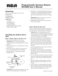
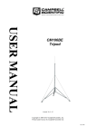
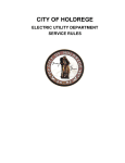
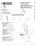
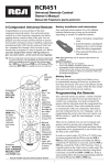
Programmable Antenna Rotator
VH126N User's Manual
Unpacking
Make sure the following pieces are in the box:
(1) Drive unit
(1) Control unit
(1) Remote control
Hardware kit:
(2) U Bolts
(4) Threaded inserts
(3) U Bolt brackets
(1) Guy wire bracket
(8) Nuts with lock washers attached
(4) Nuts without washers
Installing the Outdoor Drive
Unit
Step 1: Attach cable to the drive unit
1. Run cable (not included) to the drive unit.
IMPORTANT: Up to 280’ (84m) of 20AWG 3
conductor cable may be used. For longer runs, use heavier
gauge wire.
2. Unscrew the single screw on the bottom door. Swing
the door open.
3. Remove the grommet and insert the cable thru the
slot. Press the grommet back into the housing.
4. Separate leads for 1.5”(4cm) and strip off the
insulation for 0.5”.
Third wire
to #3
Drive unit
3
2
Second wire
to #2
Terminal
1
Cover
Grommet
Silver (or wide) wire
to #1
IMPORTANT: To avoid moisture collecting in the cable
make sure the cable jacket passes thru the grommet.
5. Find the silver- or wide-jacketed lead and connect it
to terminal 1. Connect the adjacent lead to terminal
2. Connect the third lead to terminal 3. If 4 wire
cable is used, connect both wire 3 and 4 to Terminal
3.
IMPORTANT: Make sure there are no loose strands
which can short between terminals.
6. Doublecheck the wiring order. Close the door and
screw it back into place.
Step 2: Mount the drive unit
If you’re not mounting the unit inside a tower, you’ll
need to mount it to a separate mast (not included). This
kit comes with the necessary hardware for mounting.
CAUTION: Select a mounting location where the
antenna cannot come in contact with power lines while it
is being installed, and where the installation will not fall
across power lines if a guy wire should fail.
1. Screw the 4 threaded inserts in the four holes in the
side of the drive unit base. One end of each insert
has a slot you will use with a flat-head screwdriver
to make sure the inserts are in as far as they will go.
Make sure you put the opposite end in the drive unit.
Then screw the inserts as far as they will go into the
drive unit.
2. Screw the washerless nuts onto the inserts until they
are snug against the drive unit.
3. Put the largest of the four brackets onto the ends of
the bottom two inserts. Put the nuts with attached
lock washers on the very end of the inserts to keep the
bracket in place.
4. Put one of the other brackets onto the ends of the top
two inserts. Put the nuts with attached lock washers
on the very end of the inserts to keep the bracket in
place.
5. Position the brackets and nuts/washers so that they
leave just enough room for the support mast to go
through.
6. Lower the drive unit onto the support mast until it
stops on the mast nose of the drive housing. Tighten
the nuts. Moderate tightening with a 7/16” wrench
will cause the teeth to grip the mast securely.
continues on next page...
Mast nose
Drive unit
Support mast
Lower bracket
Guy wire
5. Lower the antenna mast between the brackets and
the rotor. Tighten the nuts. Moderate tightening with
a 7/16” wrench will cause the teeth to grip the mast
securely.
6. After connecting the antenna lead-in cable to the
antenna, fasten it to the antenna mast using stand-off
insulators (not included) as shown. Provide a generous
loop at the drive unit.
7. Attach the lead-in cable to the support mast with
stand-off insulators (not included) approximately
every four feet.
8. Tape the rotator control cable directly to the support
mast.
IMPORTANT: Do not overtighten to the point that you
deform the mast, since this will reduce its strength. Mast
diameters of 1.25” to 2” (3-5cm) may be used. The 1.5” Installing and Programming
(3.8cm) size or larger is recommended for unguyed masts
the Indoor Control Unit
over 6’ long, or where large antennas are used. If guy
wires are used, fasten two through each of the two holes of Step 1: Set up to the control unit
the lower bracket.
1. Determine the length of cable needed to run between
the outdoor and indoor units. Cut the cable to that
length.
Step 3: Install the antenna/cable
2. Strip about 1/2” of the jacket off the end of each wire.
1. Insert the 2 U-bolts through the back of the rotor
1/2"
section of the drive unit.
3 wire #3 to #3
2. Place the remaining 2 brackets over the ends of the
2 wire #2 to #2
U-bolts.
1 wire #1 to #1
3. Put the nuts with attached lock washers on the very
3. Insert each bare wire into the connector plate on the
end of the U-bolts to keep the brackets in place.
control unit’s back panel as shown below.
4. Position the brackets and nuts/washers so that they
leave just enough room for the antenna mast to go
through.
Note: Use no more than 3” of antenna mast between the
rotor and the antenna itself.
Antenna
Stand-off
Loop to allow
full turn of antenna
Antenna
mast (3”)
Drive
unit
Control cable
Stand-off
Tape to mast
Antenna
lead-in cable
Support mast
4. Release jacket to secure on connector.
IMPORTANT: The unit must be wired correctly.
Damage can result from improper wiring.
5. Plug power cord of the control unit into AC outlet.
6. Turn on the unit.
The CHANNEL on the front panel reads 0, and the
ANT POSITION display reads 00.
Step 2: Program the control unit
1. Press the INITIAL key on the control unit’s
front panel keypad. The control unit and rotator
are initializing to prepare for initial setup. The
CHANNEL and POSITION indicators blink during
this process, which takes about a minute and a half.
When the CHANNEL and POSITION indicators
stops blinking, the control unit and rotator are ready
for setup.
2. Press the INITIAL key. The ANT POSITION display
shows 36 to 0.
CHANNEL
ANT POSITION
SENSOR
A
B
C
D
E
F
G
H
I
J
U
INITIAL
DEG. X10
SEC.
L
MEMORY
LEARN
NOTES:
• You must perform the learning procedure before installing
the antenna mast. This procedure allows you to make sure
the rotator goes the entire 360º with no problems. See the
Learning section below for more information.
• A strong storm or power failure may cause the rotator to
change position. Use the INITIAL key to re-synchronize
the system. If this reset procedure doesn’t get the desired
results, the antenna of driver motor may be misaligned
on the antenna mast. You can either go to the antenna
and re-orient it or program the control unit to correspond
to the new antenna orientation.
3. Tune your TV to the station that you want to receive.
4. While watching your TV screen, press the < and >
keys on the control unit’s front panel to move the
antenna clockwise (>) and counter-clockwise (<) until
you find the position that gives you the best reception
for this channel.
A
B
C
D
E
F
G
H
I
J
U
L
INITIAL
MEMORY
LEARN
5. When you’ve found the best antenna position for
this channel, press the MEMORY key on the control
unit’s front panel. The ANT POSITION indicator
blinks.
6. Press one of the letter keys on the control unit’s front
panel to store the antenna position for this station to
that key. The ANT POSITION indicator shows the
degree of the antenna’s position.
Note: Using a letter key that already has a position stored
to it in this step erases the old position stored and stores
the new one.
7. The back of the control unit’s remote control has a
chart for recording the channel and antenna position
corresponding to each letter key. Write down this
information on this chart.
8. Repeat steps 3-7 for the next TV station. Choose a
different letter key to store its location.
You can store up to 12 antenna positions so that you
can easily find the best reception for each TV station.
Step 3: Install batteries in the remote
1. Press and push the
battery compartment
cover to remove it.
2. Insert the batteries,
matching the batteries
to the (+) and (–)
marks inside the
battery compartment.
3. Push the battery cover
back into place.
Battery Precautions:
• Do not mix old and new batteries.
• Do not mix alkaline, standard (carbon-zinc) or
rechargeable (nickel cadmium) batteries.
• Always remove old, weak or worn-out batteries promptly
and recycle or dispose of them in accordance with Local
and National Regulations.
Using the Programmable
Antenna Rotator
To go to a programmed antenna position: Press the
letter key for that position on the remote or on the
control unit’s front panel.
The drive unit turns the antenna to that position, and
the control unit displays the position of the antenna in
degrees.
To stop the rotator while it’s going to a programmed
position: Turn the control unit off, then turn it back on.
Press the INITIAL key to resynchronize the unit.
To fine-tune the antenna position (or position
manually): Press the > or < keys on the remote control
or control unit’s front panel to move the antenna
clockwise (>) or counter-clockwise (<).
Note: If you press the INITIAL key by mistake, press
the INITIAL key again to stop the reset procedure. Then
continue with the action you were trying to perform.
Performing the Learning
Procedure
1. Simultaneously press and hold the INITIAL and >
keys (make sure you press the INITIAL key first).
The rotator turns a full 360º cycle.
2. Release both keys at the same time. The ANT
POSITION indicator displays the rotator cycle time.
The control unit uses this information to keep
the antenna positions and program locations
synchronized.
Resetting the Memory Keys
Resetting the control unit’s memory keys erases all
programmed antenna positions.
1. Turn off the control unit.
2. Press and hold the D key on the control unit’s front
panel.
3. While holding the D key, turn the control unit back
on. The < and > indicators light up.
4. Release the D key and turn the unit back off.
5. Turn the unit back on a second time. The unit will
perform the initialization procedure.
The CHANNEL on the front panel reads 0, and
the ANT POSITION display reads 00. The unit is
resetting its memory.
12 Month Limited Warranty
Audiovox Electronics Corporation (the “Company”) warrants to the original retail purchaser of this product that should this product or any part thereof, under
normal use and conditions, be proven defective in material or workmanship within 12 months from the date of original purchase, such defect(s) will be repaired
or replaced (at the Company’s option) without charge for parts and repair labor. To obtain repair or replacement within the terms of this Warranty, the product
along with any accessories included in the original packaging is to be delivered with proof of warranty coverage (e.g. dated bill of sale), specification of defect(s),
transportation prepaid, to the Company at the address shown below. Do not return this product to the Retailer.
This Warranty is not transferable and does not cover product purchased, serviced or used outside the United States or Canada. The Warranty does not extend to
the elimination of externally generated static or noise. This Warranty does not apply to costs incurred for installation, removal or reinstallation of the product,
or, if in the Company’s opinion, the product has been damaged through acts of nature, alteration, improper installation, mishandling, misuse, neglect, accident,
or the simultaneous use of different battery types (e.g. alkaline, standard or rechargeable). This Warranty does not cover damage caused by an AC adapter not
provided with the product.
THE EXTENT OF THE COMPANY’S LIABILITY UNDER THIS WARRANTY IS LIMITED TO THE REPAIR OR REPLACEMENT PROVIDED
ABOVE AND, IN NO EVENT, SHALL THE COMPANY’S LIABILITY EXCEED THE PURCHASE PRICE PAID BY PURCHASER FOR THE
PRODUCT.
This Warranty is in lieu of all other express warranties or liabilities. ANY IMPLIED WARRANTIES, INCLUDING ANY IMPLIED WARRANTY OF
MERCHANTABILITY OR FITNESS FOR A PARTICULAR PURPOSE, SHALL BE LIMITED TO DURATION OF THIS WARRANTY. ANY
ACTION FOR BREACH OF ANY WARRANTY HEREUNDER, INCLUDING ANY IMPLIED WARRANTY, MUST BE BROUGHT WITHIN
A PERIOD OF 24 MONTHS FROM THE DATE OF ORIGINAL PURCHASE. IN NO CASE SHALL THE COMPANY BE LIABLE FOR ANY
CONSEQUENTIAL OR INCIDENTAL DAMAGES WHATSOEVER. No person or representative is authorized to assume for the Company any liability
other than expressed herein in connection with the sale of this product.
Some states/provinces do not allow limitations on how long an implied warranty lasts or the exclusion or limitation of incidental or consequential damage so
the above limitations or exclusions may not apply to you. This Warranty gives you specific legal rights and you may also have other rights which vary from state/
province to state/province.
U.S.A.: Audiovox Electronics Corporation, 150 Marcus Blvd., Hauppauge, New York 11788
CANADA: Audiovox Return Center, c/o Genco, 6685 Kennedy Road, Unit 3, Door 16, Mississauga, Ontario L5T 3A5
© 2008 Audiovox Accessories Corporation
111 Congressional Blvd., Suite 350
Carmel, IN 46032
VH126N US IB 00
Trademark(s) ® Registered
Made in China
Consumer Product Safety
Commission Information
4. Do not use a metal ladder.
5. Remember, even the slightest touch of an antenna to a powerline can
cause a fatal shock.
6. Don’t try to do the job on a windy day.
7. Have a friend watch as a spotter on the ground when you’re on the roof to
see things you can’t.
8. If you start to drop the antenna, get away from it and let it fall.
9. If any part of the antenna comes in contact with a powerline—CALL
YOUR LOCAL POWER COMPANY; DON’T TRY TO REMOVE IT
YOURSELF! They will remove it safely.
10. Keep mast, lead-in and metal guy wires away from powerlines, too. They
are all excellent conductors of electrical current.
11. Be sure everyone understands the danger of touching an overhead
powerline. Tell them never to try to remove any object touching a
powerline.
12. Make sure that the antenna and its mast are properly grounded.
HOW TO SELECT AND MEASURE YOUR INSTALLATION SITE
Before attempting to install your antenna, think of where you can best
place your antenna for safety and performance. Most antennas are
supported by pipe masts attached to the chimney, roof, or side of the
house. Generally, the higher the antenna is above the ground, the
better it performs. A good practice is to install your antenna about 5 to
10 feet above the roofline and away from powerlines and obstructions.
Remember that the FCC limits your antenna height to 60 feet. If possible,
find a mounting place directly above your set, where the antenna lead-in
wire can take a short, vertical drop on the outside of the house for entry
through a wall or window near the set. To determine a safe distance from
wires, powerlines, and trees:
1. Measure the length of your antenna.
2. Add the antenna length to the height of your tower or mast.
3. Double this total for the minimum recommended safe distance.
If you cannot maintain this safe distance, STOP!
GET PROFESSIONAL HELP.
FOLLOW THESE RULES AND LIVE
1. If you’re not sure about a careful, safe installation—don’t try to do it
yourself. Call your local power company or check with Yellow Pages under
“Antennas or Television and Radio Antenna Systems” for an installer in
your area.
2. With at least two people, assemble as much of the antenna on the ground
as possible.
3. Watch out for overhead powerlines. Check the distance to the powerlines
before you start installing—WE RECOMMEND YOU STAY A MINIMUM
OF TWICE THE MAXIMUM LENGTH OF THE ANTENNA AND ITS
MAST AWAY FROM ALL POWERLINES.
ANTENNA GROUNDING
To protect your house and your TV/FM installation, your antenna system must
be properly grounded.
1. Clamp a #10 copper or #8 aluminum grounding wire to the base of the
antenna mast. Using stand-offs every 4 to 6 feet, run the wire down the
building in as straight a line as possible.
2. Attach a 300-Ohm static discharge unit (lightning arrestor) or a 75-Ohm
grounding block to the antenna’s lead-in cable as close as possible to the
point where the cable enters the house.
3. Attach the grounding wire to the lead-in cable’s grounding unit and run
the wire to the central building ground.
Acceptable central building ground points may include:
• Grounded interior metal cold water pipe within five feet of the point where
it enters the building
• Grounded metallic service raceway
• Grounded electrical service equipment enclosure
• 8-foot grounding rod driven into the ground (only if bonded to the central
building ground by #6 or heavier bonding wire)
• Other acceptable electrodes that comply with the sections 250 and 810 of
the National Electrical Code (NEC)