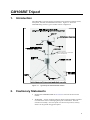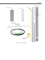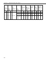
1
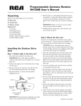
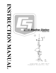
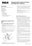
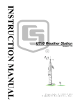
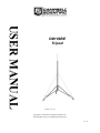
USER MANUAL CM106BE Tripod Issued: 9.11.15 Copyright © 2005-2015 Campbell Scientific, Inc. Printed under licence by Campbell Scientific Ltd. CSL 1063 Guarantee This equipment is guaranteed against defects in materials and workmanship. We will repair or replace products which prove to be defective during the guarantee period as detailed on your invoice, provided they are returned to us prepaid. The guarantee will not apply to: Equipment which has been modified or altered in any way without the written permission of Campbell Scientific Batteries Any product which has been subjected to misuse, neglect, acts of God or damage in transit. Campbell Scientific will return guaranteed equipment by surface carrier prepaid. Campbell Scientific will not reimburse the claimant for costs incurred in removing and/or reinstalling equipment. This guarantee and the Company’s obligation thereunder is in lieu of all other guarantees, expressed or implied, including those of suitability and fitness for a particular purpose. Campbell Scientific is not liable for consequential damage. Please inform us before returning equipment and obtain a Repair Reference Number whether the repair is under guarantee or not. Please state the faults as clearly as possible, and if the product is out of the guarantee period it should be accompanied by a purchase order. Quotations for repairs can be given on request. It is the policy of Campbell Scientific to protect the health of its employees and provide a safe working environment, in support of this policy a “Declaration of Hazardous Material and Decontamination” form will be issued for completion. When returning equipment, the Repair Reference Number must be clearly marked on the outside of the package. Complete the “Declaration of Hazardous Material and Decontamination” form and ensure a completed copy is returned with your goods. Please note your Repair may not be processed if you do not include a copy of this form and Campbell Scientific Ltd reserves the right to return goods at the customers’ expense. Note that goods sent air freight are subject to Customs clearance fees which Campbell Scientific will charge to customers. In many cases, these charges are greater than the cost of the repair. Campbell Scientific Ltd, 80 Hathern Road, Shepshed, Loughborough, LE12 9GX, UK Tel: +44 (0) 1509 601141 Fax: +44 (0) 1509 601091 Email: [email protected] www.campbellsci.co.uk PLEASE READ FIRST About this manual Please note that this manual was originally produced by Campbell Scientific Inc. primarily for the North American market. Some spellings, weights and measures may reflect this origin. Some useful conversion factors: Area: 1 in2 (square inch) = 645 mm2 Length: 1 in. (inch) = 25.4 mm 1 ft (foot) = 304.8 mm 1 yard = 0.914 m 1 mile = 1.609 km Mass: 1 oz. (ounce) = 28.35 g 1 lb (pound weight) = 0.454 kg Pressure: 1 psi (lb/in2) = 68.95 mb Volume: 1 UK pint = 568.3 ml 1 UK gallon = 4.546 litres 1 US gallon = 3.785 litres In addition, while most of the information in the manual is correct for all countries, certain information is specific to the North American market and so may not be applicable to European users. Differences include the U.S standard external power supply details where some information (for example the AC transformer input voltage) will not be applicable for British/European use. Please note, however, that when a power supply adapter is ordered it will be suitable for use in your country. Reference to some radio transmitters, digital cell phones and aerials may also not be applicable according to your locality. Some brackets, shields and enclosure options, including wiring, are not sold as standard items in the European market; in some cases alternatives are offered. Details of the alternatives will be covered in separate manuals. Part numbers prefixed with a “#” symbol are special order parts for use with non-EU variants or for special installations. Please quote the full part number with the # when ordering. Recycling information At the end of this product’s life it should not be put in commercial or domestic refuse but sent for recycling. Any batteries contained within the product or used during the products life should be removed from the product and also be sent to an appropriate recycling facility. Campbell Scientific Ltd can advise on the recycling of the equipment and in some cases arrange collection and the correct disposal of it, although charges may apply for some items or territories. For further advice or support, please contact Campbell Scientific Ltd, or your local agent. Campbell Scientific Ltd, 80 Hathern Road, Shepshed, Loughborough, LE12 9GX, UK Tel: +44 (0) 1509 601141 Fax: +44 (0) 1509 601091 Email: [email protected] www.campbellsci.co.uk Precautions DANGER — MANY HAZARDS ARE ASSOCIATED WITH INSTALLING, USING, MAINTAINING, AND WORKING ON OR AROUND TRIPODS, TOWERS, AND ANY ATTACHMENTS TO TRIPODS AND TOWERS SUCH AS SENSORS, CROSSARMS, ENCLOSURES, ANTENNAS, ETC. FAILURE TO PROPERLY AND COMPLETELY ASSEMBLE, INSTALL, OPERATE, USE, AND MAINTAIN TRIPODS, TOWERS, AND ATTACHMENTS, AND FAILURE TO HEED WARNINGS, INCREASES THE RISK OF DEATH, ACCIDENT, SERIOUS INJURY, PROPERTY DAMAGE, AND PRODUCT FAILURE. TAKE ALL REASONABLE PRECAUTIONS TO AVOID THESE HAZARDS. CHECK WITH YOUR ORGANIZATION'S SAFETY COORDINATOR (OR POLICY) FOR PROCEDURES AND REQUIRED PROTECTIVE EQUIPMENT PRIOR TO PERFORMING ANY WORK. Use tripods, towers, and attachments to tripods and towers only for purposes for which they are designed. Do not exceed design limits. Be familiar and comply with all instructions provided in product manuals. Manuals are available at www.campbellsci.eu or by telephoning +44(0) 1509 828 888 (UK). You are responsible for conformance with governing codes and regulations, including safety regulations, and the integrity and location of structures or land to which towers, tripods, and any attachments are attached. Installation sites should be evaluated and approved by a qualified engineer. If questions or concerns arise regarding installation, use, or maintenance of tripods, towers, attachments, or electrical connections, consult with a licensed and qualified engineer or electrician. General • Prior to performing site or installation work, obtain required approvals and permits. Comply with all governing structure-height regulations, such as those of the FAA in the USA. • Use only qualified personnel for installation, use, and maintenance of tripods and towers, and any attachments to tripods and towers. The use of licensed and qualified contractors is highly recommended. • Read all applicable instructions carefully and understand procedures thoroughly before beginning work. • Wear a hardhat and eye protection, and take other appropriate safety precautions while working on or around tripods and towers. • Do not climb tripods or towers at any time, and prohibit climbing by other persons. Take reasonable precautions to secure tripod and tower sites from trespassers. • Use only manufacturer recommended parts, materials, and tools. Utility and Electrical • You can be killed or sustain serious bodily injury if the tripod, tower, or attachments you are installing, constructing, using, or maintaining, or a tool, stake, or anchor, come in contact with overhead or underground utility lines. • Maintain a distance of at least one-and-one-half times structure height, or 20 feet, or the distance required by applicable law, whichever is greater, between overhead utility lines and the structure (tripod, tower, attachments, or tools). • Prior to performing site or installation work, inform all utility companies and have all underground utilities marked. • Comply with all electrical codes. Electrical equipment and related grounding devices should be installed by a licensed and qualified electrician. Elevated Work and Weather • Exercise extreme caution when performing elevated work. • Use appropriate equipment and safety practices. • During installation and maintenance, keep tower and tripod sites clear of un-trained or non-essential personnel. Take precautions to prevent elevated tools and objects from dropping. • Do not perform any work in inclement weather, including wind, rain, snow, lightning, etc. Maintenance • Periodically (at least yearly) check for wear and damage, including corrosion, stress cracks, frayed cables, loose cable clamps, cable tightness, etc. and take necessary corrective actions. • Periodically (at least yearly) check electrical ground connections. WHILE EVERY ATTEMPT IS MADE TO EMBODY THE HIGHEST DEGREE OF SAFETY IN ALL CAMPBELL SCIENTIFIC PRODUCTS, THE CUSTOMER ASSUMES ALL RISK FROM ANY INJURY RESULTING FROM IMPROPER INSTALLATION, USE, OR MAINTENANCE OF TRIPODS, TOWERS, OR ATTACHMENTS TO TRIPODS AND TOWERS SUCH AS SENSORS, CROSSARMS, ENCLOSURES, ANTENNAS, ETC. Contents PDF viewers: These page numbers refer to the printed version of this document. Use the PDF reader bookmarks tab for links to specific sections. 1. Introduction ................................................................ 1 2. Cautionary Statements .............................................. 1 3. Initial Inspection ........................................................ 2 3.1 3.2 3.3 Inspect Packaging ................................................................................ 2 Tripod Components.............................................................................. 2 Tools List (for tripod, mast, enclosures, and crossarms) ...................... 4 4. Overview ..................................................................... 4 5. Specifications ............................................................ 5 6. Installation .................................................................. 6 6.1 Tripod Installation ................................................................................ 6 6.1.1 Tripod Base ................................................................................... 6 6.1.1.1 Mounting on a Relatively Flat Area ................................... 7 6.1.1.2 Mounting on an Incline ...................................................... 7 6.1.2 Mast .............................................................................................. 8 6.1.3 Installing the Optional Guy Kit ................................................... 10 6.1.4 Staking the Tripod Feet ............................................................... 12 6.1.5 Tripod Grounding ....................................................................... 13 6.1.6 Crossarm Attachment.................................................................. 15 6.1.7 Enclosure Attachment ................................................................. 15 6.1.7.1 Enclosure Mounting to Tripod Mast ................................ 15 6.1.7.2 Enclosure Mounting to Tripod Leg .................................. 16 6.2 Mounting Brackets ............................................................................. 18 6.2.1 CM210 Crossarm Mounting Kit ................................................. 18 6.2.2 CM216 Mast Mounting Kit - 009902 ......................................... 19 6.2.3 CM220E Right Angle Mounting Kit .......................................... 20 6.2.4 Crossarm Brace Kit ..................................................................... 21 6.2.5 CM225E and 010716 Pyranometer Mounting Stand .................. 21 6.2.6 CM230 Adjustable Angle Mounting Kit..................................... 24 6.2.7 CM235 Magnetic Mounting Stand ............................................. 26 6.2.8 Radiation Shields for temperature and humidity probes ............. 27 i Appendix A. CM106B Allowable Wind Speeds .......................... A-1 Figures 1-1. 3-1. 4-1. 6-1. 6-2. 6-3. 6-4. 6-5. 6-6. 6-7. 6-8. 6-9. 6-10. 6-11. 6-12. 6-13. 6-14. 6-15. 6-16. 6-17. 6-18. 6-19. 6-20. 6-21. 6-22. Typical tripod-based weather station ................................................... 1 Tripod components .............................................................................. 3 CM106BE tripod with lightning rod and guy wires ............................. 4 Tripod leg, leg clamp components ....................................................... 6 Comparison of one leg pointing downhill (right) versus two legs pointing downhill.............................................................................. 7 Tripod mast and insert ......................................................................... 8 Mast attachment to tripod base ............................................................ 9 Guy collar .......................................................................................... 10 Leg attachment ................................................................................... 11 Staking the tripod feet ........................................................................ 12 Ground rod and clamp ....................................................................... 13 Lightning rod ..................................................................................... 14 CM204E Crossarm............................................................................. 15 Enclosure with the –MM bracket ....................................................... 16 Enclosure with the –LM bracket ........................................................ 17 CM210E Crossarm Mounting Kit (shown with user-supplied pipe).. 18 CM216 Mast Mounting Kit................................................................ 19 CM220E Right Angle Mounting Kit.................................................. 20 CMB200 Crossarm Brace Kit ............................................................ 24 CMB200 components ........................................................................ 24 Bracket selection ................................................................................ 24 CM225E Pyranometer Mounting ....................................................... 24 CM230 Adjustable Angle Mounting Kit ............................................ 25 CM235 Magnetic Mounting Stand..................................................... 26 R.M. Young Radiation Shield ............................................................ 27 ii CM106BE Tripod 1. Introduction The CM106BE is a general purpose tripod that can be used for mounting sensors, solar panels, antennas, and instrument enclosures. Figure 1-1 shows the CM106BE being used in a typical weather station configuration. CS300 Pyranometer Base & Levelling Fixture, CM225 Solar Sensor Mounting Stand Figure 1-1. Typical tripod-based weather station 2. Cautionary Statements READ AND UNDERSTAND the Precautions section at the front of this manual. WARNING — Ensure structural integrity during setup and weather extremes to minimize the chance of damaging the tripod or instruments. Read all instructions carefully. Once the tripod is in full vertical position, securely fasten it to the ground using ground spikes. 1 CM106BE Tripod 3. WARNING — For installations where soil structure is questionable or the tripod may experience high wind loads, concrete footings for the tripod feet and guy anchors should be considered. Initial Inspection 3.1 Inspect Packaging Upon receiving the CM106BE, inspect the packaging and contents for damage. Claims for shipping damage must be filed with the shipping company. Locate the packing slip for the order and compare the items listed on the packing slip to the items that were actually shipped. Report any discrepancies to Campbell Scientific. 3.2 Tripod Components Figure 3-1 shows the tripod components. The tripod base is packaged with the mast, mast extension, ground rod, lightning rod, and (3) stakes. The ground rod clamp, lightning rod, lightning rod clamp, cable ties, and ground wires are enclosed in a bag. The optional guy kit is packaged separately. 2 User Manual Mast Extension (20) Cable Ties (3) Stakes Mast Base Lightning Rod and Clamp Ground Wires Ground Rod and Clamp Figure 3-1. Tripod components 3 CM106BE Tripod 3.3 Tools List (for tripod, mast, enclosures, and crossarms) 13 mm and 10 mm open end wrenches Adjustable wrench Phillips head screw drivers (medium, small) Straight bit screwdrivers (large, medium) 300 mm torpedo level Side-cut pliers Pencil Tape measure Compass and site declination angle Shovel Sledge hammer (for driving ground rod and stakes) Step ladder 4. Overview The CM106BE (Figure 4-1) is constructed from galvanized steel, with individually adjustable legs that allow installation over uneven terrain. The CM106BE includes lightning and ground rods, ground cables, UV resistant cable ties, and stakes for securing the tripod feet to the ground. An optional guy kit is recommended for sites that experience high wind speeds (see Section 5, Specifications). Instrument enclosures can be purchased with mounting brackets that attach to either the mast or leg section as shown in Section 6.1.7, Enclosure Attachment. The CM106BE can be used for a variety of applications. For meteorological stations, sensors are mounted to the tripod using mounting brackets appropriate for the model of sensor. For non-meteorological applications, the tripod can be used to mount instrument enclosures, solar panels, junction boxes, or antennas. Figure 4-1. CM106BE tripod with lightning rod and guy wires 4 User Manual 5. Specifications Mast Height Upper Mast Retracted: 2.1 m to 2.8 m Upper Mast Extended: 3 m to 3.7 m Vertical Load Limit: 200 kg Mast Outer Diameter Main Lower Mast: Retractable Upper: 48.0 mm 42.50 mm Base Diameter: 2.7 m to 3.5 m Levelling Adjustment: Slide collars on each leg, adjust individually Leg Base: 118 mm by 140 mm with four 16 mm holes for stakes Portability: Collapsible to 200 mm diameter by 1850 mm length Weight with Mast: 24.5 kg Maximum Slope Angle: 45° Allowable Wind Speeds* Tripod Configuration Sustained Wind Wind Gust Mast Extended, Unguyed 28 m s–1 (62 mph) 36 m s–1 (81 mph) Mast Retracted, Unguyed 36 m s–1 (80 mph) 46 m s–1 (104 mph) Mast Extended, Guyed 45 m s–1 (102 mph) 59 m s–1 (132 mph) Mast Retracted, Guyed 55 m s–1 (122 mph) 71 m s–1 (159 mph) *Allowable wind speed values assume: Sensors - effective area = 1300 cm2 at top of mast Solar panel – 26.5 cm x 42 cm at mast base Enclosure - 35.5 cm x 40.5 cm mounted to leg Guy wires attached to mast at 115.5 cm above tripod body Adequate ground anchors (stakes alone may not resist foot vertical pullout force) See Appendix A for more information on maximum allowable wind speeds. 5 CM106BE Tripod 6. Installation 6.1 Tripod Installation 6.1.1 Tripod Base The tripod base has three independently adjustable legs allowing the tripod to be installed over non-level terrain. Prepare the area where the tripod will be installed. The tripod requires an area approximately 2.7 to 3.5 m in diameter. Natural vegetation and the ground surface should be disturbed as little as possible, but brush and tall weeds should be removed. Stand the tripod base up on end, and rotate the feet perpendicular to the legs. Each leg has a leg clamp and clamping bolt as shown in Figure 6-1. Leg Clamp Clamping Bolt Figure 6-1. Tripod leg, leg clamp components 6 User Manual 6.1.1.1 Mounting on a Relatively Flat Area Loosen the tension bolt and extend each leg. With the legs extended, orient the tripod so that one of the legs points South (assuming the instrument enclosure with –MM Mast Mount bracket will face North). If the instrument enclosure has the – LM Leg Mount bracket, orient the tripod so the enclosure will mount to one of the three leg mount positions on the tripod, facing the desired direction. The tripod is typically plumbed after the mast has been installed, as described in Section 6.1.2, Mast. 6.1.1.2 Mounting on an Incline Loosen the tension bolt and extend each leg. With the legs extended, orient the tripod so that one leg points downhill and the other two legs point uphill. The tripod is more stable with only one leg pointed downhill because the mast is closer to the centre of the footprint (see Figure 6-2). The tripod is typically plumbed after the mast has been installed, as described in Section 6.1.2, Mast. Slope angle Figure 6-2. Comparison of one leg pointing downhill (right) versus two legs pointing downhill 7 CM106BE Tripod 6.1.2 Mast The CM106BE includes a mast extension that can be fully extended for a 3 m height, or partially extended for a 2.1 m height. Remove the bolts in the mast, align the holes in the mast extension with holes in the mast, and install the bolts previously removed. Two additional holes make it possible for the extension to extend 20.5 cm or 30.5 cm, or 51 cm, 61 cm, or 71 cm above the mast depending on which end is inserted in the mast. Mast extension fully extended Mast extension retracted Mast Figure 6-3. Tripod mast and insert 8 User Manual Preset at Factory Mast Bolts Tab Preset at Factory Figure 6-4. Mast attachment to tripod base Loosen the six bolts on the tripod base. Figure 6-4 shows the location of four of these bolts. The remaining bolts are in the same position on the third tripod leg. Slide the mast into the tripod base, making sure that it extends below the lower bolts and rests on the tabs. Tighten the six bolts to secure the mast. If required, also loosen the 6 x preset at factory bolts. Plumb the tripod by adjusting the northeast and south facing legs. With a level on the East side of the mast, adjust the Northeast leg for plumb. With the level on the South side of the mast, adjust the South leg for plumb. Tighten the tension bolts after the adjustments have been made. Make sure all bolts have been tightened. 9 CM106BE Tripod 6.1.3 Installing the Optional Guy Kit Part 010649, CM106BE Guy Kit, can be ordered separately for areas that experience high wind speeds (Section 5, Specifications). Install the guy brackets to the mast as shown in Figure 6-5. Attach the three guy wires to the guy collar and slide the collar over the mast so that the collar butts against the brackets. Guy Collar Guy Wire Guy Bracket Figure 6-5. Guy collar On the end of each guy line is a case and hardware to attach to the turnbuckles. Unscrew the turnbuckles so that only (12.5 mm of wire extends beyond the inside of the turnbuckle body. Attach the case and turnbuckle to the tripod leg as shown in Figure 6-6. Loosen the two clamp nuts, and remove the slack in the guy wire by feeding the load end of the guy wire through the case while pulling up on the free end. After the slack has been removed from the guy wires, tighten the clamp nuts, and then tighten the turnbuckles to the desired tension. 10 User Manual Clamp Nut Figure 6-6. Leg attachment 11 CM106BE Tripod 6.1.4 Staking the Tripod Feet Three stakes are provided for securing the tripod feet to the ground. Drive one pin through a hole in each foot at an angle as shown in Figure 6-7. Pins may not be adequate depending on soil structure, maximum wind speeds experienced at the site, mast height, or wind load from the instrumentation. For questionable situations, additional pins (pn 001831) or even concrete footings for the tripod feet and guy anchors should be considered. Figure 6-7. Staking the tripod feet 12 User Manual 6.1.5 Tripod Grounding Place the clamp over the ground rod and drive the rod (close to the centre of the tripod) using a sledge hammer or fence post driver. Strip 12.5 mm of insulation from both ends of the green/yellow 16 mm2 ground wire. Insert one end of the ground wire into the clamp and ground rod and tighten the bolt on the clamp. Attach the other end of the ground wire to the lug on the tripod base as shown in Figure 6-8. Trim length to suit. Enclosure Ground Lug Ground Lug Ground Wire Enclosure Ground Wire Figure 6-8. Ground rod and clamp 13 CM106BE Tripod Strip 12.5 mm of insulation from the ends of the green/yellow 6 mm2 wire. Attach one end of the wire to the tripod ground lug, and the other end to the enclosure ground lug as shown in Figure 6-8. Mount the lightning rod and clamp to the tripod mast with pointed tip up, and notch at bottom (Figure 6-9). Lightning Rod Clamp Mast Figure 6-9. Lightning rod 14 User Manual 6.1.6 Crossarm Attachment Attach the CM202E (0.6 m), CM204E (1.2 m), or CM206E (1.8 m) crossarm to the tripod mast as shown in Figure 6-10. For wind sensors, the crossarm should be approximately 2.6 m above the ground for a 3 m mounting height, or 1.6 m for a 2 m mounting height (the exact height depending on the type of sensors being used). Typically the crossarm is oriented East/West for wind sensors, North/South for pyranometers. CM200 Series Crossarm Tripod Mast Figure 6-10. CM204E Crossarm 6.1.7 Enclosure Attachment The ENC10/12, ENC12/14, ENC14/16, and ENC16/18 enclosures can be ordered with mounting brackets for the CM106BE tripod. All enclosure models can be mounted to the tripod mast (above the legs) with the –MM Mast Mount bracket option. The –LM Leg Mount bracket option allows all enclosure models to be mounted to the tripod base. Two enclosures with the –LM brackets can be mounted in a “back to back” configuration. 6.1.7.1 Enclosure Mounting to Tripod Mast An enclosure ordered with the –MM bracket has a three-piece top and bottom brackets with a V-bolt for each bracket. Attach an enclosure with the –MM mounting bracket to the tripod mast as follows: Remove the V-bolts, washers, and nuts from the brackets. Position the enclosure against the tripod’s mast (North side recommended). Install the V-bolts, flat washers, lock washers, and nuts (Figure 6-11). Tighten the nuts until the lock washers are compressed. 15 CM106BE Tripod Route the 6 mm2 wire from the ground lug on the bottom side of the enclosure to the ground lug on the base of the tripod (Figure 6-8). Strip 12.5 mm of insulation from each end of the wire. Insert wire ends into the ground lugs and tighten. V-Bolt Figure 6-11. Enclosure with the –MM bracket 6.1.7.2 Enclosure Mounting to Tripod Leg An enclosure ordered with the –LM bracket has a bracket on each side of the enclosure, and a V-bolt bracket for securing the enclosure to a tripod leg. Attach an enclosure with the –LM mounting bracket to the tripod base as follows: Slide the keyhole notch in upper corner of the –LM bracket over the extended hook located on the tripod base as shown in Figure 6-12, and engage the notch in the lower corner of the –LM bracket with the enclosure tab. There are six places on the tripod base with provisions for mounting enclosures with the –LM brackets. Remove the washers, nuts, and V-bolt from the V-bolt bracket. Install the bracket as shown in Figure 6-12 (top). Tighten the nuts on the V-bolt until the lock washers are compressed. Route the 6 mm2 wire from the ground lug on the bottom side of the enclosure to the ground lug on the base of the tripod (Figure 6-8). Strip 12.5 mm of insulation from each end of the wire. Insert wire ends into the ground lugs and tighten. 16 User Manual Washers V-Bolt V-Bolt Bracket Figure 6-12. Enclosure with the –LM bracket 17 CM106BE Tripod 6.2 Mounting Brackets Mounting brackets covered in this section have V-bolts that attach to vertical and/or horizontal pipes with the following ranges of outside diameters: V-bolt Description OD Range 46 mm 25 to 38 mm 62 mm 33 to 54 mm 62 mm w/plastic V-block 25 to 54 mm 6.2.1 CM210 Crossarm Mounting Kit CM200E series crossarms include a CM210E bracket as shown in Figure 6-13. The CM210E can be ordered separately to attach a user-supplied pipe (25 mm to 38 mm OD) to a mast or tower leg (25 mm to 54 mm OD), or to attach a crossarm to two tower legs. CM210E Figure 6-13. CM210E Crossarm Mounting Kit (shown with user-supplied pipe) 18 User Manual 6.2.2 CM216 Mast Mounting Kit - 009902 The CM216 attaches to the top of the mast, and provides a 19 mm or 25.4 mm mounting pipe that extends 100 mm above the mast, as shown in Figure 6-14. CM216 Figure 6-14. CM216 Mast Mounting Kit 19 CM106BE Tripod 6.2.3 CM220E Right Angle Mounting Kit The CM220E attaches a vertical pipe (25.4 mm to 38 mm OD) to the CM200Eseries crossarms or horizontal pipe (25.4 mm to 38 mm OD) as shown in Figure 6-15. CM220E CM220E Figure 6-15. CM220E Right Angle Mounting Kit 20 User Manual 6.2.4 CMB200 Crossarm Brace Kit 6.2.4.1 Overview The CMB200 Crossarm Brace Kit (Figure 6-16) is designed to provide additional stability to crossarms mounted on Campbell Scientific tripods and towers. It provides additional support for crossarms with heavier sensor loads, and added stability in high winds. Short Tab Long Tab Figure 6-16. CMB200 Crossarm Brace Kit 6.2.4.2 Components The CMB200 ships with the following components (Figure 6-17): (1) Brace Arm (2) Small bracket (2) Medium bracket (2) Large bracket (4) 1/4-20 x 1-inch bolt (8) 1/4 flat washer (4) 1/4 lock washer (4) 1/4-20 nut 21 CM106BE Tripod Figure 6-17. CMB200 components 6.2.4.3 Assembly 1. Each bracket has a long tab and short tab where the bolts are attached. The brace arm must be attached to the end with the long tab. NOTE 22 Consult Figure 6-18 and Table 6-1 to determine which brackets are needed at either end of the brace to attach it to the crossarm and tripod mast or tower. The figure also indicates what orientation is needed when the small bracket is used. 2. Attach one end of the brace arm to the tripod mast or tower below the crossarm. Leave the bolts finger-tight. 3. Lift the free end of the brace arm to the crossarm and attach it to the crossarm. Again, only finger-tighten the bolts. 4. Adjust the position of the brace arm as needed. 5. Fully tighten the two bolts directly connected to the brace arm, and then tighten the remaining two bolts to clamp the brace arm to the crossarm and tower or tripod mast. User Manual Attaching to Ø2.54 cm (1.00 in) Members Attaching to Ø3.17 cm (1.25 in) or Ø3.32 cm (1.31 in) Members Attaching to Ø4.82 cm (1.90 in) Members Figure 6-18. Bracket selection Table 6-1. Bracket Requirements Mast/Crossarm/ Tower Diameter Example Mast/Crossarm/Tower Brackets Needed Small Bracket Orientation Ø2.54 cm (1.00 in) ATW3, UT930 Tower Leg (1) Small Bracket (1) Medium Bracket Angled toward mast/tripod Ø3.17 cm (1.25 in) or Ø3.32 cm (1.31 in) CM202/3/4/6 Crossarm, (1) Small Bracket (1) Medium Bracket Angled away from mast/tripod Ø4.82 cm (1.90 in) CM110/106BE Tripod (2) Large Bracket N/A 23 CM106BE Tripod 6.2.5 CM225E Pyranometer Mount The CM225E is used to attach a pyranometer or quantum sensor to a horizontal or vertical pipe (25.4 mm to 54 mm OD). The LI200X pyranometer and LI190SB quantum sensor mount to the CM225E via the LI200S levelling base (see Figure 6-19). The CS300 pyranometer mounts to the CM225E via the 010355 levelling base. The CMP3 and LP02 pyranometers include their own bubble level and levelling screws allowing them to mount directly to the CM225E. CM225E LI200X Pyranometer (The CS300 mounts in a similar way.) LI2003S CM225E Figure 6-19. CM225E Pyranometer Mounting 6.2.6 CM230 Adjustable Angle Mounting Kit The CM230 mounts an antenna (25.4 mm to 38 mm OD) to a mast or vertical pipe (33 mm to 54 mm OD) as shown in Figure 6-20. The bracket allows the antenna to be adjusted for different angles. 24 User Manual CM230 Figure 6-20. CM230 Adjustable Angle Mounting Kit 25 CM106BE Tripod 6.2.7 CM235 Magnetic Mounting Stand The CM235 provides an 89 mm square platform for mounting magnetic base antennas. The CM235 attaches to horizontal or vertical pipes (25.4 mm to 54 mm OD) as shown in Figure 6-21. Figure 6-21. CM235 Magnetic Mounting Stand 26 User Manual 6.2.8 Radiation Shields for temperature and humidity probes These Radiation Shields are used to house and attach temperature and relative humidity sensors to the tripod mast (25.4 mm to 54 mm OD) or crossarm as shown in Figure 6-22. Radiation shields ship with the V-bolt configured for attachment to a vertical pipe. To attach the radiation shield to a horizontal pipe, the V-bolt and plastic V-block must be moved to the other set of holes. Various brands of shields are available from Campbell Scientific, including R M Young and Met Spec. They are mounted in a similar way. Figure 6-22. R.M. Young Radiation Shield 27 Appendix A. CM106BE Allowable Wind Speeds CM106B load ratings assume: Tripod Footprint Dia. Mast Height ft ft 11.5 8.7 11.5 m 3.5 2.7 3.5 7 9.3 10 Mast Configuration Sensors - effective area = 0.13m2 at top of mast Solar panel – 26.5 cm x 42 cm at mast base Enclosure – 35.5 cm x 40.5 mounted to leg Guy wires attached to mast at 115.5 cm above tripod body Adequate ground anchors (stakes alone may not resist foot vertical pullout force) Max. Allowable Equipment Weight Foot Vertical Pullout Force at Gust Speed GuyWire Tension at Gust Speed Ideal GuyWire Installation PreTension m/s lb kg lb kN lb kN lb kN 104 46 964 438 70 0.31 - - - - Attached to legs @ feet, 45deg Zenith 159 71 639 289 163 0.73 300 1.3 150 0.67 Independent anchors @ 45deg Zenith 159 71 639 289 56 0.25 300 1.3 150 0.67 Unguyed 104 46 964 438 160 0.71 - - - - Attached to legs @ feet 159 71 438 198 352 1.57 400 1.8 200 0.89 Independent anchors @ 45deg Zenith 159 71 639 289 155 0.69 300 1.3 150 0.67 Unguyed 81 36 964 438 59 0.26 - - - - Attached to legs @ feet, 45deg Zenith 132 59 544 246 157 0.70 400 1.8 200 0.89 Independent anchors @ 45deg Zenith 132 59 544 246 17 0.08 400 1.8 200 0.89 Max. Allowable Gust Wind Speed mph Unguyed Guy Anchors m 2.1 2.8 3.0 Retracted Retracted Extended A-1 Appendix A. CM106BE Allowable Wind Speeds Tripod Footprint Dia. Mast Height ft ft 8.7 A-2 m 2.7 12.3 Mast Configuration Max. Allowable Equipment Weight Foot Vertical Pullout Force at Gust Speed GuyWire Tension at Gust Speed Ideal GuyWire Installation PreTension m/s lb kg lb kN lb kN lb kN 81 36 964 438 121 0.54 - - - - Attached to legs @ feet 116 52 438 198 248 1.10 400 1.8 200 0.89 Independent anchors @ 45deg Zenith 132 59 544 246 69 0.31 400 1.8 200 0.89 Max. Allowable Gust Wind Speed mph Unguyed Guy Anchors m 3.7 Extended CAMPBELL SCIENTIFIC COMPANIES Campbell Scientific, Inc. (CSI) 815 West 1800 North Logan, Utah 84321 UNITED STATES www.campbellsci.com [email protected] Campbell Scientific Africa Pty. Ltd. (CSAf) PO Box 2450 Somerset West 7129 SOUTH AFRICA www.csafrica.co.za [email protected] Campbell Scientific Australia Pty. Ltd. (CSA) PO Box 8108 Garbutt Post Shop QLD 4814 AUSTRALIA www.campbellsci.com.au [email protected] Campbell Scientific do Brazil Ltda. (CSB) Rua Apinagés, nbr. 2018 - Perdizes CEP: 01258-00 São Paulo SP BRAZIL www.campbellsci.com.br [email protected] Campbell Scientific Canada Corp. (CSC) 14532 – 131 Avenue NW Edmonton, Alberta T5L 4X4 CANADA www.campbellsci.ca [email protected] Campbell Scientific Centro Caribe S.A. (CSCC) 300N Cementerio, Edificio Breller Santo Domingo, Heredia 40305 COSTA RICA www.campbellsci.cc [email protected] Campbell Scientific Ltd. (CSL) 80 Hathern Road, Shepshed, Loughborough LE12 9GX UNITED KINGDOM www.campbellsci.co.uk [email protected] Campbell Scientific Ltd. (France) 3 Avenue de la Division Leclerc 92160 ANTONY FRANCE www.campbellsci.fr [email protected] Campbell Scientific Spain, S. L. Avda. Pompeu Fabra 7-9 Local 1 - 08024 BARCELONA SPAIN www.campbellsci.es [email protected] Campbell Scientific Ltd. (Germany) Fahrenheitstrasse13, D-28359 Bremen GERMANY www.campbellsci.de [email protected] Campbell Scientific (Beijing) Co., Ltd. 8B16, Floor 8 Tower B, Hanwei Plaza 7 Guanghua Road, Chaoyang, Beijing 100004 P.R. CHINA www.campbellsci.com [email protected] Please visit www.campbellsci.com to obtain contact information for your local US or International representative.