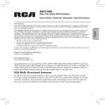
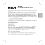
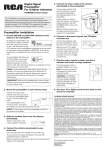
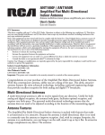
1
ENGLISH
ANT3037X
Outdoor Antenna
Installation Manual
Point Toward Stations
Mast not included
with antenna.
BEFORE YOU START!!!
Please read the IMPORTANT SAFETY INFORMATION sheet included in
this package.
WARNING
Installation of this antenna near power lines is dangerous. For your safety,
follow the installation instructions.
1
Parts List
Back Assembly (VHF)
Front Assembly (UHF)
Small Flange Nut (6)
Washer (6)
Corner Reflector (2)
Large Screw (2)
Mast Clamp Insert
U-Bolt
Matching
Transformer
Large Flange Nut
for U-Bolt (2)
Low Band VHF Add-On Kit For RF Channels 2–6
and/or FM (Not Needed for Most Installations, See Page 3.)
Large Screw
Clip
Element Extension with Both Ends Crimped
Small Flange Nut (17)
Element
Sleeves (8) Element Extensions (8)
2
Small Screw (16)
Things to Consider Before Installing
the Antenna
ENGLISH
Location Selection
Digital broadcast signals travel via line of sight. That means the fewer
objects between your antenna and the broadcast tower, the stronger your
signal will be. Installing your antenna in the attic may reduce the signal
by as much as 50%, so it is always recommended to install the antenna
outdoors for maximum performance.
Before deciding on a location for this antenna, determine which channels
you want to receive and where they are coming from. This will help you
determine the best location and direction to aim the antenna.
For this information, go online to www.tvsetfree.com, www.antennaweb.
org, or www.tvfool.com. Each of these sites has a feature that allows you to
enter your address and get a listing of likely channels available in your area,
including a map showing each station’s tower in relation to your location.
Do I Need to Install the Low Band VHF Kit?
On www.antennaweb.org, if you have an RF channel (right column) 2–6,
you will need the Low Band VHF Kit. On www.tvfool.com, if you have a real
channel 2–6, you will need the Low Band VHF Kit. If you don’t have any low
band VHF channels in your area but want FM reception, then you need to
install the Low Band VHF Kit. Most areas will not need the kit.
For most channels, stations will only come from one or two directions. If
the compass headings are similar (less than 30° apart), the antenna can be
aimed between the areas and receive signals from each location.
The antenna has a maximum range of up to 65 miles when installed outside
and used with a high-quality preamplifier. Any station outside this range
is less likely to be picked up by the antenna. This range is reduced by any
obstructions (such as trees, buildings, or hills) between the antenna and
the broadcast tower and is subject to broadcast strength, frequency, and
meteorological factors. Installing without a preamplifier will reduce the
antenna’s range.
Distance, obstructions and compass heading all play a role in deciding on
a location to permanently mount the antenna. For this reason, it may be
necessary to try the antenna in several locations while checking the signal
on multiple channels. Moving the antenna three feet in one direction is often
enough to change the reception. Re-scan your TV or converter box each
time you move the antenna.
3
Assembling the Antenna
Start by unfolding the VHF elements on the back assembly until the
elements are perpendicular to the boom (Figure 1). You should hear the
elements click into place.
After
Before
VHF Elements
Boom
Boom
Figure 1
Unfold the six UHF elements on the front assembly until they are
perpendicular to the boom. See Figure 2. You should hear the pieces click
into place. Pull the two phasing lines away from the boom.
Before
Figure 2
Boom
Unfolded
Elements
After
Fold out Elem
Fol
Elements
m
Phasing
Lines
Boom
On the back assembly, remove the nut and screw from the plastic block
nearest to the open end of the boom and to the mast clamp (Figure 3).
Open End
of Boom
Screw
Removal
Site
Figure 3
4
Slide the crimped end of the front assembly boom into the open end of the
back assembly boom (Figure 4). Re-insert the screw into the plastic block
closest to the mast clamp, and secure with the flange nut.
ENGLISH
Front Assembly
Back Assembly
Crimped End
Screw
Insertion Mast
Clamp
Site
Figure 4
Then, slip the phasing lines onto the threaded rivets near the reflector
brackets. Add a washer onto each rivet. Thread a small nut onto each rivet.
See Figure 5.
Top View
Side View
Reflector Bracket
Rivet
Phasing
Lines
Phasing
Lines
Figure 5
Unfold the elements on the two corner reflectors as in Figure 6. You should
hear the pieces click into place.
After
Before
Corner Reflector
Figure 6
5
Insert the open end of one corner reflector in-between the top of the
reflector brackets (Figure 7). (Elements should be on top.) Align the holes
in the brackets with the hole in the corner reflector. Insert a large screw
through the holes. Thread a small flange nut on the screw.
Figure 7
Reflector Brackets
Next, insert the open end of the second corner reflector in-between the
bottom of the reflector brackets (Figure 8). (Elements should be on bottom.)
Align the holes in the brackets with the hole in the corner reflector. Insert a
large screw through the holes. Thread a small flange nut on the screw.
Figure 8
Tighten the two flange nuts. See Figure 9.
Figure 9
Screws
6
Adding the Low Band VHF Add-On Kit
For RF Channels 2–6 and/or FM
If unsure whether or not to install the Low Band VHF Add-On Kit, see the
section “Do I Need to Install the Low Band VHF Kit?” on page 3.
Locate the hole in the bottom of the boom near the mast clamp.
Mast Clamp
Figure 10
Hole
7
ENGLISH
If you determined that you need the Low Band VHF Add-On Kit, proceed
with the steps on the next page. If you determined that you do not need
the Low Band VHF Add-On Kit (page 2), continue with attaching the coax
cable on page 9.
Insert the large screw through the hole in the bottom of the boom (Figure
11). Place the element extension with crimped ends onto the screw. Then,
install the clip onto the element extension with crimped ends so that the
holes in both parts align. Thread a small flange nut on the screw, and
tighten.
Figure 11
Large Screw
Element Extension
with Crimped Ends
Place each element extension beside the element to which it will connect.
The shortest element extension will connect to the shortest element on
the back assembly, and the longest element extension will connect to the
longest element. The element extensions should decrease in length as they
near the center of the antenna (Figure 12). One element sleeve will be used
to connect each element extension to its corresponding element.
Figure 12
Shortest Element
Extension
Longest Element
Extension
8
Before
Holes to Align
Holes to Align
Figure 13
After
Top
Bottom
Attaching a Coax Cable
Locate the two posts on the underside of
the front assembly (Figure 14). Place two
washers on each post. Loosely thread a
small nut onto each post. Slide one fork of
the matching transformer between a set of
washers. Repeat for the other fork on the
other post. Tighten the nuts, making sure
that the forks are still connected.
Figure 14
Posts
9
ENGLISH
Slide the element sleeve over the element. Align the holes in the element
sleeve and element. Then, slide the element extension into the element
sleeve. Align the holes in the element sleeve and element extension. Insert a
small screw through the top of each hole, and thread a small flange nut onto
each screw. Repeat for connecting each element extension to an element.
See Figure 13.
Remove the rubber boot from the matching
transformer. Slide the rubber boot over the
coax cable and install the connector. If your
coax cable has the connector already on it, you
will need to cut an X in the boot hole so that
the boot will slide over the connector. Attach
the coax cable to the matching transformer.
Then, connect the rubber boot to the body of
the matching transformer, as in Figure 15.
Rubber Boot
Fork
Figure 15
Mounting the Antenna
Place the mast clamp insert inside the mast
clamp so that the flat side of the mast clamp
insert presses against the boom. The holes in
both parts should align. Insert the ends of the
U-bolt through the holes. The mast should be
placed in-between the U-bolt and the mast
clamp insert. Thread a large nut on each end
of the U-bolt. Tighten the nuts until the U-bolt
securely holds the mast in place. The U-bolt
assembly will handle up to a 2.0” outer diameter
mast.
Helpful Tips
•
Be sure the matching transformer is on the
bottom of the antenna.
•
Point the front of antenna toward stations.
•
Tape downlead to mast to prevent wind
whipping.
10
Figure 16
Providing Lightning Protection for
the Antenna
ENGLISH
1. Mount lightning arrestor or 75 ohm grounding block as close as
possible to where lead-in enters house.
2. Ground wires for both mast and lead-in should be copper or
aluminum wire, number 8 or larger.
3. Lead-in wire from antenna to lightning arrestor or 75 ohm grounding
block and mast ground wire should be secured to house with stand-off
insulators, spaced from four to six feet apart.
4. In the case of a “ground up” antenna installation, it may not be
necessary to ground the mast if the mast extends four or more feet
into the earth. Consult your TV service man for proper depth in your
area.
Example of antenna grounding as per
National Electrical Code, ANSI/NFPA 70
Antenna
Lead-In Wire
Ground
Clamp
Grounding Conductors
(NEC Section 810-21)
Electric
Service
Equipment
Antenna
Discharge Unit
(NEC Section 810-20)
(May substitute a 75 ohm
Coax Grounding Block)
Ground
Clamps
Rain Drip Loop On
Lead-In To TV
Power Service Grounding
Electrode System
(NEC Art 250, Part H)
NEC - National Electrical Code
11
Amplifying the Signal
The signal received at the antenna is all the signal the system will ever
have; amplifiers can only prevent losing this signal as it runs to one or more
televisions. Therefore, mounting location and direction are very important.
An amplifier or pre-amplifier may be required if any of the following applies:
• The cable between the antenna and the television is longer than 50
feet.
•
More than one television is connected to the antenna.
•
The received signal is not strong enough to ensure consistent
performance.
If you have questions, contact RCA at 1-800-290-6650 or visit
RCAAudioVideo.com.
Note: We recommend using this antenna with a high quality preamplifier,
such as the RCA TVPRAMP1R, available at many retailers or from
RCAAudioVideo.com.
12
Troubleshooting
Possible Cause
There is static or snow in the
picture.
Digital television is all or nothing; the
picture is crystal clear, or there isn’t
one. Static means there is interference
between the digital tuner and the
television screen. If you use a digital
converter, one of the connections or
the cable between the converter and
television may be bad, or the channel
is analog. When using a converter box,
make sure the TV set and the output
channel of the converter box are on the
same channel.
I am not getting channels.
Several things can cause this:
• There is a faulty connection
between the antenna and the
converter box.
• The matching transformer
may have come loose from the
antenna.
Try running a new channel scan on the
TV or converter box. Try the antenna
in a new location. Something may be
obstructing the signal.
One channel is missing.
Try turning the antenna 10 or 20
degrees in either direction to avoid
reflection or for better peak on the
signal.
The picture/sound freezes while
I am watching TV, or there are
boxes in the picture.
This is often caused by a weak or
intermittent signal. Try moving the
antenna to a better location or aiming it
directly at the tower for this channel.
13
ENGLISH
Issue
12 Month Limited Warranty
VOXX Accessories Corporation (the “Company”) warrants to the original retail
purchaser of this product that should this product or any part thereof, under
normal use and conditions, be proven defective in material or workmanship within
12 months from the date of original purchase, such defect(s) will be repaired or
replaced (at the Company’s option) without charge for parts and repair labor. To
obtain repair or replacement within the terms of this Warranty, the product along
with any accessories included in the original packaging is to be delivered with proof
of warranty coverage (e.g. dated bill of sale), specification of defect(s), transportation
prepaid, to the Company at the address shown below. Do not return this product to
the Retailer.
This Warranty is not transferable and does not cover product purchased, serviced
or used outside the United States or Canada. The warranty does not extend to the
elimination of externally generated static or noise. This Warranty does not apply
to costs incurred for installation, removal or reinstallation of the product, or, if in
the Company’s opinion, the product has been damaged through acts of nature,
alteration, improper installation, mishandling, misuse, neglect, or accident. This
warranty does not cover damage caused by an AC adapter not provided with the
product.
THE EXTENT OF THE COMPANY’S LIABILITY UNDER THIS WARRANTY IS LIMITED
TO THE REPAIR OR REPLACEMENT PROVIDED ABOVE AND, IN NO EVENT, SHALL
THE COMPANY’S LIABILITY EXCEED THE PURCHASE PRICE PAID BY PURCHASER
FOR THE PRODUCT. This Warranty is in lieu of all other express warranties or
liabilities. ANY IMPLIED WARRANTIES, INCLUDING ANY IMPLIED WARRANTY
OF MERCHANTABILITY OR FITNESS FOR A PARTICULAR PURPOSE, SHALL
BE LIMITED TO DURATION OF THIS WARRANTY. ANY ACTION FOR BREACH
OF ANY WARRANTY HEREUNDER, INCLUDING ANY IMPLIED WARRANTY,
MUST BE BROUGHT WITHIN A PERIOD OF 24 MONTHS FROM THE DATE OF
ORIGINAL PURCHASE. IN NO CASE SHALL THE COMPANY BE LIABLE FOR ANY
CONSEQUENTIAL OR INCIDENTAL DAMAGES WHATSOEVER. No person or
representative is authorized to assume for the Company any liability other than
expressed herein in connection with the sale of this product.
Some states/provinces do not allow limitations on how long an implied warranty
lasts or the exclusion or limitation of incidental or consequential damage so the
above limitations or exclusions may not apply to you. This Warranty gives you
specific legal rights and you may also have other rights which vary from state/
province to state/province.
U.S.A.: Audiovox Return Center, 150 Marcus Blvd., Hauppauge, NY 11788
CANADA: Audiovox Return Center, c/o Genco, 6685 Kennedy Road, Unit #3 Door 14,
Mississauga Ontario L5T 3A5
©2013 VOXX Accessories Corporation
3502 Woodview Trace, Suite 220, Indianapolis, IN 46268
ANT3037X NA IB 01
14