1
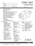
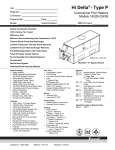
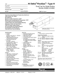
MVB™ - Type H Job: Engineer: Heating/Hot Water Supply Boilers Models H7 504-2004 Contractor: Prepared By: Model: Date: Indoor/Outdoor: 84% Thermal Efficiency at Full Rate 100% Factory Fire Tested Maximum Outlet Water Temperature: 220°F Minimum Acceptable Inlet Water Temperature: 120°F Full Safety Diagnostics with History Footprint: Less Than 5-1/2 ft2 Limited Twenty-Year Thermal Shock Warranty Limited Ten-Year Heat Exchanger Warranty Electronic Modulation, Constant Ratio 1.4:1 Turndown TempTracker Mod Controller with LCD Display Status Display Lights Heat Exchanger Bronze Headers ASME H Stamped 160 PSIG Working Pressure National Board Approved Fin Tubing Copper – Standard Cupro Nickel – Option A-3 ASME Powder-Coated Tube Sheet Silicone High Temp O-Rings ASME Pressure Relief Valve 60 PSIG – Standard PSIG – Optional Temperature and Pressure Gauge, Shipped Loose Stainless Steel Evaporator Plate Control 120V, 60Hz, 1Ø, Power Supply 120/24V 60Hz Transformer Ignition Module 3-Try – Standard Single-Try – Option C-6 Hot Surface Ignition (HSI) Remote Flame Sensor High Limit, Manual Reset, Fixed, 240ºF On/Off Power Switch Flow Switch Blocked Vent Pressure Switch Combustion Air Proving Switch Pump Switch Pump Time Delay Diagnostics Panel Modulating Temperature Control Water Temperature Sensors (3) Catalog No.: 2000.364A Burner Ultra-Low NOx: Less than 20 PPM Gas Train Fuel Natural Gas Propane Zero Governor Regulator Dual-Seat Combination Valve Electronic Modulating Firing Mode Construction Indoor/Outdoor Construction Front Controls Enclosed PolyTuf Powder Coat Finish Rear Connections (Water, Electrical, Gas, Vent, Combustion Air) Design Certified ANSI Z21.13/ CSA 4.9 Venting Vent Termination Cap Outdoor - Option D-11 Indoor, Horizontal – Option D-15 Indoor, Vertical (by others) Combustion Air In-Line Filter Kit – Option D-17 Air Intake Elbow – Option D-16 Extractor – Optional By others Not required Effective: 8-15-07 Temperature Controllers B-36 Temp-Tracker Mod+ Digital Controller, Up to 4 Boilers, OA Reset B-37 Temp-Tracker Mod+ Digital Controller, Up to 10 Boilers, OA Reset B-38 Temp-Tracker Mod+ Digital Controller, Up to 16 Boilers, OA Reset Y-241 Electronic Sequencer, Up to 4 Boilers Y-281 Electronic Sequencer, Up to 8 Boilers Options A-13 Air Vent, Auto, 150 PSI F-10 Low Water Cut-Off, Remote Probe I-1 High Limit, Auto Reset, Adj., 100-240°F I-2 High Limit, Manual Reset, Adj., 100-240°F PPump: HP, 120V, 1∅, 60Hz Water Hardness: GPG Cast Iron Bronze Loose Mounted PCold Water Start PCold Water Run S-1 Low Gas Pressure Switch, Manual Reset S-2 High Gas Pressure Switch, Manual Reset Regulatory Agency Requirements Replaces: 6-15-07 MVB™ – Type H Models H7 504-2004 Model CLEARANCES Front Rear Right Left Top Floor Vent Certified Minimum 24” 12” 1” 1” 0” 0” 1” Recomm. Service 24” 24” --10” --- PUMP HP – AMPS* Model (H7-) Soft 504 754 1104 1504 2004 1/4 - 6 1/4 - 6 1/4 - 6 1/2 - 7 1 - 14 Water Hardness Medium Hard 1/4 - 6 1/2 - 7 1/2 - 7 1 - 14 1-1/2 - 15 3/4 - 11 3/4 - 11 1 - 14 1 - 14 1-1/2 - 15 * Current draw is for pump only Model (H7-) 504 754 1104 1504 2004 MBTUH Input Output B Height 500 750 1100 1500 1999 420 630 924 1260 1679 43 49 55 61 75 D E F 30 36 43 50 61 35 41 47 53 65 23-3/4 29-3/4 35-3/4 41-3/4 53-3/4 Dimensions (in.) G H K NPT NPT Flue Ø 1 1 1-1/4 1-1/4 2 2 2 2-1/2 2-1/2 2-1/2 8 10 10 12 14 M N C/A Ø P R V Ship Weight (Lbs.) Footprint 2 (Ft ) Amps* 14-1/8 16 16 18-1/8 20-1/8 6 6 6 8 8 36 42 49 53 69 6 6 6 6 9 2 2 2 2 5 600 670 720 780 940 5.4 5.4 5.4 5.4 5.4 12 12 12 12 18 - Ratings shown are for elevations up to 4,500 feet. For installations at elevations above 4,500 feet, please consult the factory for additional instructions. - For direct vent applications, please contact the factory about relocating the pump. * Current draw is for heater only. (Supply breaker must have delayed trip.) RATES OF FLOW AND PRESSURE DROPS Model (H7-) 504 754 1104 1504 2004 20°F ∆T GPM ∆P (ft.) 42 63 92 N/A N/A 2.7 6.0 13.3 N/A N/A 30°F ∆T GPM ∆P (ft.) 28 42 62 84 112 1.4 2.9 6.7 13.3 26.9 40°F ∆T* GPM ∆P (ft.) N/A 32 46 63 84 N/A 1.7 4.1 8.0 16.0 Maximum Flow GPM ∆P (ft.) ∆T (°F) 100 100 113 113 113 11.3 13.8 18.6 22.2 27.2 8 13 16 22 30 Minimum Flow* GPM ∆P (ft.) ∆T (°F) 25 32 46 63 84 1.1 1.7 4.1 8.0 16.0 34 40 40 40 40 * Closed systems only Raypak, Inc. 2151 Eastman Avenue, Oxnard, CA 93030 (805) 278-5300 Fax (800) 872-9725 www.raypak.com Raypak Canada Ltd. 2805 Slough St., Mississauga, Ontario, Canada L4T 1G2 (905) 677-7999 Fax (905) 677-8036 www.raypakcanada.com Catalog No.: 2000.364A Effective: 8-15-07 Replaces: 6-15-07