1
USERS INFORMATION MANUAL
FOR GAS FIRED BOILERS
CATALOG NO.: 2000.52G
Effective:
06-01-00
Replaces: 07-01-94
WARNING: If the information in this manual is not followed exactly, a fire or explosion may result
causing property damage, personal injury or loss of life.
-
Do not store or use gasoline or other flammable vapors and liquids or other combustible
materials in the vicinity of this or any other appliance. To do so may result in an explosion or
fire.
-
WHAT TO DO IF YOU SMELL GAS
• Do not try to light any appliance.
• Do not touch any electrical switch; do not use any phone in your building.
• Immediately call your gas supplier from a neighbor's phone. Follow the gas supplier's
instructions.
• If you cannot reach your gas supplier, call the fire department.
-
Installation and service must be performed by a qualified installer, service agency or the gas
supplier.
CAUTIONS: Propane gas is heavier than air and sinks to the ground. Exercise extreme care in lighting heater
in confined areas.
Do not use this boiler if any part has been under water. Immediately call a qualified service technician to
inspect the boiler and to replace any part of the control system and any gas control which has been under water.
Should overheating occur or the gas supply fail to shut off, do not turn off or disconnect the electrical supply
to the pump. Instead, shut off the gas supply at a location external to the appliance.
Raypak recommends that this manual be reviewed thoroughly before installing your Raypak Boiler. If there
are any questions which this manual does not answer please contact your local Raypak representative or the
factory.
OPERATING CONTROLS
Model W1 with On/Off Controls
The boiler is equipped with an adjustable tankstat. Set dial for desired temperature.
Models with Mechanical Modulation: H1, H5, W2, N, R
Sizes 133 through 1826. These boilers are equipped with modulating gas valves. They have one or more valves
in addition to the main electric gas valve. Their purpose is to adjust the firing rate to meet the required load. The
modulator will throttle the boiler input to meet the system demand. The valve has a remote capillary bulb immersed
in a well at the header outlet to maintain a constant outlet water temperature. When multiple valves are furnished,
they can be staged to give greater flexibility of control. Consult the dial setting tag attached to the control for your
desired water temperature.
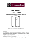
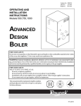
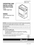
MODULATING VALVE CHART —7000
DIAL POSITION
Lo
1
2
3
4
5
6
7
8
Hi
TEMPERATURE —°F
N
H
W
R
110
150
117
157
124
164
130
170
137
177
143
183
150
190
156
196
163
203
170
210
MODULATING VALVE (ROBERTSHAW)
Fig. # 8936.1
P/N 240412
Models with Motorized Modulation: H2, H6, W2
Sizes 2100-4001 are equipped with a single motorized modulating valve
controller that offers full modulation down to 20% of rated input BTU.
TEMP CONTROL
FOR MOTORIZED MODULATION
HIGH LIMIT AND
TEMP CONTROL
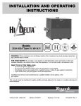
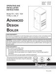
LIMIT CONTROLS
1. HIGH LIMIT
If boiler is equipped with a manual reset High Limit,
push the reset button and set the Limit(s) to 30° - 40°F
above operating temperature.
5. HIGH AND LOW GAS PRESSURE SWITCHES
These switches sense either high or low gas pressures and automatically shut down burners if abnormal
pressures exist.
2. FLOW SWITCH
Dual purpose control shuts off boiler in case of
pump failure or low water condition.
6. BLOCKED VENT SHUT-OFF SYSTEM
All indoor boilers below 300,000 BTUH input employ a blocked vent shut-off system designed to shut off
main burner gas in the event the venting system is
totally blocked.
In the event the blocked vent shut-off system is
actuated, do not attempt to place the boiler in operation,
but contact a qualified service agency.
3. 100% PILOT SAFETY
All standard boilers above 400,000 BTUH input are
equipped with pilot safety(ies), which close the main
valve within 8/10 of a second whenever the pilot flame
is interrupted. Pilot flame is automatically lit when the
device is powered. Unit performs its own safety check
and opens the main valve only after the pilot is proven
to be lit.
4. LOW WATER CUTOFF
The low water cut off automatically shuts down
burner whenever water level drops below probe. 90
second time delay prevents premature lockout due to
temporary conditions such as power failure or air pockets.
1
2
3
MANUAL RESET
HI LIMIT
Fig # 9314
FLOW SWITCH
controlled by a temperature
7. FLAME ROLL-OUT
SAFETY SHUT-OFF SYSTEM
All boilers below 300,000 BTUH input employ a
flame roll-out safety shut-off system designed to shutoff the main burner gas in the event of sustained flame
roll-out.
In the event the flame roll-out safety system is
actuated, do not attempt to place the boiler in operation,
but contact a qualified service agency
PILOT SAFETY
Fig # 9317
Fig # 8929
2
4
5
LOW WATER
CUTOFF
HIGH OR LOW GAS
PRESSURE SWITCH
Fig # 9316
Fig # 9312
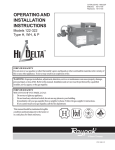
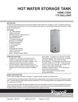
GENERAL LOCATION OF CONTROLS
ELECTRICAL J-BOX
OUTLET
T & P GAUGE
(Not Shown)
INLET
MODULATING
GAS VALVES WITH
REGULATOR
HI-LIMIT
PILOT LOCATIONS
SEDIMENT TRAP
(BY OTHERS)
MANUAL GAS VALVE
FIG.# S8185.0
START-UP PROCEDURE
LIGHTING INSTRUCTIONS
BOILERS WITH MANUALLY LIT PILOTS
GENERAL
FOR YOUR SAFETY READ BEFORE OPERATING
Before lighting a new installation, water should be
flowing through the heater.
WARNING: If you do not follow these instructions
exactly , a fire or explosion may result causing property
damage, personal injury or loss of life.
CAUTION: Propane gas is heavier than air and sinks
to the ground. Exercise extreme care in lighting heater
in confined areas.
A. This appliance has a pilot which must be lighted
by hand. When lighting the pilot, follow these instructions exactly.
B. BEFORE LIGHTING Smell all around the appliance area for gas. Be sure to smell next to the
floor because some gas is heavier than air and
will settle on the floor.
WHAT TO DO IF YOU SMELL GAS
* Do not try to light any appliance.
* Do not touch any electric switch:
* Do not use any phone in your building.
* Immediately call your gas supplier from a
neighbor's phone.
Follow the gas supplier's instructions.
* If you cannot reach your gas supplier, call
the fire department.
C. Use only your hand to push in or turn the gas
control knob. Never use tools. If the knob will
INITIAL START-UP – PUMP AND MOTOR
Many pumps are now direct drive. They have no
coupler or bearing assembly. These pumps do not
require lubrication. Others require SAE-30 non-detergent oil to lubricate both the motor and the bearing
assembly. Consult motor manufacturer's instructions.
Clean dust and lint from pump and motor. Check
pump coupler and tighten if necessary.
Flush system before putting into operation to assure that foreign material does not damage pump
seals.
CAUTION:
A. Pump must be off to check oil in bearing
assembly.
B. Do not run pump without water in system.
3
not push in or turn by hand, do not try to repair it,
call a qualified service technician. Force or attempted repair may result in a fire or explosion.
D. Do not use this appliance if any part has been
under water. Immediately call a qualified service
technician to inspect the appliance and to
replace any part of the control system and any
gas control which has been under water.
10.
LIGHTING INSTRUCTIONS
1.
2.
3.
4.
5.
11.
12.
13.
STOP! Read the safety information above.
Set the thermostat on the lowest setting.
Turn off all electric power to the appliance.
Remove boiler door panel.
Push in gas control knob slightly and turn clockwise
to “OFF”.
goes out, repeat steps 5 through 9.
* If knob does not pop up when released, stop
and immediately call your service technician or
gas supplier.
* If the pilot does not stay lit after several tries,
turn the gas control knob to “OFF” and call
your service technician or gas supplier.
Stand to the side of the boiler and turn the gas
control knob counter clockwise
to “ON”.
Replace boiler door panel.
Turn on all electric power to the appliance.
Set the thermostat to the desired setting.
TO TURN OFF GAS TO APPLIANCE
1.
2.
3.
4.
Set the thermostat to the lowest setting.
Turn off all electric power to the appliance.
Remove boiler door.
Push in the gas control knob slightly and turn
clockwise to
"OFF". Do not force.
5. Replace boiler door panel.
GAS CONTROL KNOB SHOWN IN "OFF" POSITION
GAS CONTROL KNOB
SHOWN IN "OFF" POSITION
BOILERS WITH AUTOMATICALLY LIT IID PILOTS
AND MANUAL GAS VALVES
FOR YOUR SAFETY READ BEFORE OPERATING
GAS INLET
WARNING: If you do not follow these instructions
exactly, a fire or explosion may result causing property
damage, personal injury or loss of life.
Fig. # 8081
Fig. # 8243.0
NOTE: Knob cannot be turned from “PILOT” to
“OFF” unless knob is pushed in slightly. Do not
force.
A. This appliance is equipped with an ignition device
which automatically lights the pilot. Do not try to
light the pilot by hand.
B. BEFORE OPERATING Smell all around the
appliance area for gas. Be sure to smell next to
the floor because some gas is heavier than air
and will settle on the floor.
WHAT TO DO IF YOU SMELL GAS
* Do not try to light any appliance.
* Do not touch any electric switch:
do not use any phone in your building.
* Immediately call your gas supplier from a
neighbor's phone, follow the gas supplier's
instructions.
* If you cannot reach your gas supplier, call
the fire department.
C. Use only your hand to push in or turn the gas
control knob. Never use tools. If the knob will
not push in or turn by hand, do not try to repir it,
call a qualified service technician.
D. Do not use this appliance if any part has been
under water. Immediately call a qualified service
6. Wait five (5) minutes to clear out any gas. Then
smell for gas, including near the floor. If you smell
gas, STOP! Follow "B" in the safety information
above on this label. If you don't smell gas, go to the
next step.
7. Locate pilot mounted on the burner drawer.
8. Turn knob on gas control counter clockwise
to “PILOT”.
THERMOCOUPLE
PILOT
BURNER
Fig.# 8083
9. Push in control knob all the way and hold in.
Immediately light the pilot with a match. con
tinue to hold the control knob in for about one (1)
minute after the pilot is lit. Release knob and it
will pop back up. Pilot should remain lit. If it
4
BOILERS WITH AUTOMATICALLY LIT IID
PILOTS AND AUTOMATIC GAS VALVES
technician to inspect the appliance and to
replace any part of the control system and any
gas control which has been under water.
Lighting Instructions
1. Close all gas valves. Turn off electric power
supply. Wait 5 minutes.
2. Open manual pilot valve. Turn on electric
power. Pilot is automatically lighted.
3. Open main gas valve.
4. Set temperature controls to desired temperature.
LIGHTING INSTRUCTIONS
1.
2.
3.
4.
5.
6.
7.
8.
STOP! Read the safety information above.
Set the thermostat on the lowest setting.
Turn off all electric power to the appliance.
This appliance is equipped with an ignition
device which automatically lights the pilot. Do
not try to light the pilot by hand.
Remove boiler door panel.
Turn gas control knob clockwise
to
“OFF”. Make sure knob rest against stop.
Wait five (5) minutes to clear out any gas. Then
smell for gas, including near the floor. If you smell
gas, STOP! Follow "B" in the safety information
above on this label. If you don't smell gas, go to the
next step.
Turn gas control knob counter clockwise
to “OFF” until it stops. Push in gas control knob
and continue rotating counter clockwise
to “ON” position. Make sure knob rest against
stop.
To Shut Down
Close all manual gas valve. Turn off electric
power.
Fig. # 8929.1
IGNITION MODULE
GAS CONTROL
KNOB SHOWN
IN "ON"
POSITION
BOILERS WITH AUTOMATICALLY LIT C2/IRI
PILOT AND MANUAL GAS VALVES
FOR YOUR SAFETY READ BEFORE OPERATING
GAS INLET
Fig.# 8082
9.
10.
11.
12.
WARNING: If you do not follow these instructions
exactly, a fire or explosion may result causing property
damage, personal injury or loss of life.
Replace boiler door panel.
Turn on all electric power to the appliance.
Set thermostat to desired setting.
If the appliance will not operate, follow the
instructions “TO Turn Off Gas To Appliance”
and call your service technician or gas supplier.
A. This appliance is equipped with an ignition device
which automatically lights the pilot. Do not try to
light the pilot by hand.
B. BEFORE OPERATING Smell all around the appliance area for gas. Be sure to smell next to the floor
because some gas is heavier than air and will settle
on the floor.
WHAT TO DO IF YOU SMELL GAS
* Do not try to light any appliance.
* Do not touch any electric switch:
do not use any phone in your building.
* Immediately call your gas supplier from a neighbor's phone, follow the gas supplier's instructions.
* If you cannot reach your gas supplier, call the
fire department.
TO TURN OFF GAS TO APPLIANCE
1. Set the thermostat to the lowest setting.
2. Turn off all the electric power to the appliance if
service is to be performed.
3. Remove boiler door panel.
4. Turn gas control knob clockwise
to
"OFF". Make sure knob rest against stop.
5. Replace boiler door panel.
5
C. Use only your hand to push in or turn the gas
control knob. Never use tools. If the knob will not
push in or turn by hand, do not try to repair it, call
a qualified service technician. Force or attempted
repair may result in a fire or explosion.
2. Turn off all the elctric power to the appliance if
service is to be performed.
3. Remove boiler door panel.
4. Turn gas control knob clockwise
to
"OFF". Make sure knob rest against stop.
5. Replace boiler door panel.
D. Do not use this appliance if any part has been
under water. Immediately call a qualified service
technician to inspect the appliance and to
replace any part of the control system and any
gas control which has been under water.
BOILERS WITH AUTOMATICALLY LIT C2/IRI
PILOT AND AUTOMATIC GAS VALVES
1. Close all gas valves. Turn off electric power
supply. Wait five (5) minutes.
2. Open manual pilot valve. Turn on electric
power. Push and release electric control reset
button (Center of control cover). Pilot is automatically lighted.
3. Open main gas valve.
4. Set temperature controls to desired temperature.
LIGHTING INSTRUCTIONS
1.
2.
3.
4.
5.
6.
7.
8.
9.
STOP! Read the safety information.
Set the thermostat on the lowest setting.
Turn off all electric power to the appliance.
This appliance is equipped with an ignition
device which automatically light the pilot. Do
not try to light the pilot by hand.
Remove boiler door panel.
Turn gas control knob clockwise
to
“OFF”. Make sure knob rest against stop.
Wait five (5) minutes to clear out any gas. Then
smell for gas, including near the floor. If you smell
gas, STOP! Follow "B" in the safety information
above on this label. If you don't smell gas, go to the
next step.
Turn gas knob counter clockwise
from
"OFF" until it stops. Push in gas control knob
and continue rotating counter clockwise
to "ON" position. Make sure knob rest against
stop.
Replace boiler door panel.
To Shut Down
Close all manual gas valves. Turn off electric
power.
FLAME SAFETY
CONTROL
RELAY
Fig.# 9318
INSPECTION PROCEDURES
GAS CONTROL
KNOB SHOWN
IN "ON"
POSITION
BURNERS
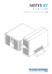
Clean main burners and air louvers of dust, lint and
debris. Keep boiler area clear and free from combustibles and flammable liquids. Do not obstruct the
flow of combustion and ventilating air. Make visual
check of burner and pilot flame. Yellow flame indicates
clogging of air openings. Lifting or blowing flame
indicates high gas pressure. Low flame indicates low
gas pressure.
GAS INLET
Fig.# 8082
10. Turn on all electric power to the appliance.
11. Push in and release electric control reset button
(center of control cover). Pilot is automatically
lighted.
12. Set thermostat to desired setting.
13. If the appliance will not operate, follow the
instructions “To Turn Off Gas To Appliance” and
call your service technician or gas supplier.
NOTE: Modulating burner flame varies in height from
approximately 1/4" at low fire to approximately 3" at
high fire.
CONTROLS
TO TURN OFF GAS TO APPLIANCE
Check all controls to see that they are operational.
To check IID's electronic safety, turn off main burner.
1. Set the thermostat to the lowest setting.
6
Observe pilot burner when shutting off pilot gas. Ignition spark should go on. Main gas valve will also drop
out.
High Limit Switch - to check high limit switch, turn
dial setting down to a point slightly below the temperature of the water leaving the boiler. The reset button
should snap out and the burner should shut off. Reset
dial to 190° F and push reset button. Burner should
light.
RAYPAK HEATING AND HOT WATER SUPPLY
EQUIPMENT LIMITED WARRANTY
SCOPE: Raypak, Inc. ("Raypak") warrants to the
original owner that all parts of this boiler which are
actually manufactured by Raypak will be free from
failure under normal use and service for the specified
warranty periods and subject to the conditions set forth
in this Warranty. Labor charges and other costs for
parts removal or reinstallation, shipping and transportation are not covered by this Warranty but are the
owner's responsibility.
HEAT EXCHANGER WARRANTY: Five (5) Years
from date of boiler installation. This includes only the
copper, bronze and cast iron waterways. Twenty (20)
Years from date of boiler installation against "Thermal
Shock" (excluded, however, if caused by boiler operation at large changes exceeding 150°F between the
water temperature at intake and boiler temperature, or
operating at boiler temperatures exceeding 230°F).
Fig.# S8144.0
MAIN BURNER FLAME
NORMAL INSPECTION PROCEDURES
ANY OTHER PART MANUFACTURED BY RAYPAK:
One (1) Year warranty from date of boiler installation, or
eighteen (18) months from date of factory shipment
based on Raypak's records, whichever comes first.
SATISFACTORY PROOF OF INSTALLATION DATE,
SUCH AS INSTALLER INVOICE, IS REQUIRED. THIS
WARRANTY WILL BE VOID IF THE BOILER RATING
PLATE IS ALTERED OR REMOVED.
Examples of misuse or neglect include, but are not
limited to, physical damage from external force, not
following installation instructions, leaving door off for
extended periods, location near corrosive gases, pump
(when supplied by us), not lubricated in accordance
with listed instructions, etc.
First and third month after initial start up and then
on an annual basis. If problems are found, refer to
Trouble Shooting guide for additional directions.
1. Remove top of boiler and inspect heat exchanger
for soot and examine venting system.
2. Remove rear header and inspect for scale deposits.
*3. Inspect pilot and main burner flame and firing rate.
*4. Inspect and operate all controls and gas valve.
*5. Visually inspect system for water leaks.
*6. A. Oil pump motor and bearing assembly, if oil
cups are provided.
B. Disconnect pump from header and check condition of pump impeller. Check condition of
bearing by attempting to move impeller from
side to side. Replace any parts showing wear.
C. Check pump coupler for wear and vibration.
7. Check flow switch paddle.
8. Clean room air intake openings to assure adequate
flow of combustion and ventilation air.
9. Keep boiler area clear and free from combustible
materials, gasoline, and other flammable vapors
and liquids.
CORPORATE HEADQUARTERS:
RAYPAK,INC.
31111 Agoura Road
Westlake Village, CA
(818) 889-1500
FAX (818) 889-4522
www.raypak.com
*Should be checked monthly. (Takes approximately 15
minutes).
When ordering parts, you must specify Model and
Serial number of boiler. When ordering under warranty
conditions, you must also specify date of installation.
7
91361
www.raypak.com
Raypak, Inc., 31111 Agoura Road, Westlake Village, CA 91361-4699
(818) 889-1500 FAX (818) 889-4522
Litho In U.S.A.