1
j"Com Transceiver Control
Computer Interface
Model:
TC-I
TC-K
TC-Y
TC-Y2
The J-Com Transceiver Control Computer Interface allows you
to control most if not all of radio functions from your computer. It
is functionally identical to the Icom CT-17, Yaesu FIF-232C,
Ten Tec 305 and Heath computer interfaces. It will work with all
radios and rig control software which use these interfaces.
•
No external power supply ...power is ‘lifted’ right from the
computer’s COMM port!
•
RFI proof ...all electronics are enclosed in a shielded DB-25
connector hood.
•
Fully hardware and software compatible...will work with any
software including DXBase, LOGic, K1EA's CT program,
Turbolog, RC-plus and many others.
•
Fully wired and tested...just plug it in and go.
•
Great for winning contests and making contacts easier than
before.
TC-I 1/8 inch phone connector. For use with ICOM IC-781, IC-765,
IC-761, IC-728, IC-735, IC-725, IC-726, IC-751A, IC-271, IC-471, ICR71, IC-R9000, IC-R7100, IC-R700, IC-R72, IC-970; Ten-Tec Delta II,
Argonaut II, Paragon, Omni VI.
TC-K DIN connector. For use with Kenwood TS-950, TS-850, TS450, T690, TS-940, TS-440, TS-140, TS-690, TS-5000, TS-711, TS811.
TC-Y1 DIN connector. For use with Yaesu FT-1000D, FT-1000, FT990, FT-980, FT-767, FT-736, FT-747; Heath SB-1400
TCCI-1 • 1
RAMSEY TRANSMITTER KITS
• FM-10 FM Stereo Transmitter
• FM-1,2,3,4 FM Wireless Microphones
• PB-1 Telephone Transmitter
RAMS
LECTR
st
ki
or
ld
Be
RAMSEY HOBBY KITS
• SG-7 Personal Speed Radar
• SS-7 Speech Scrambler
• MM-5 Music Machine
• SP-1 Speakerphone
• MD-3 Microwave Motion Detector
• PH-10 Peak hold Meter
• LC-1 Inductance-Capacitance Meter
E
EY
I CS
ON
RAMSEY RECEIVER KITS
• FR-1 FM Broadcast Receiver
• AR-1 Aircraft Band Receiver
• SR-1 Shortwave Receiver
• AA-7 Active Antenna
• SC-1 Shortwave Converter
tb
u il d e
th
rs in
e
w
RAMSEY AMATEUR RADIO KITS
• FX Series VHF and UHF Transceivers
• HR Series HF All Mode Receivers
• QRP Series HF CW Transmitters
• CW-700 Micro Memory CW Keyer
• PA Series VHF and UHF Power Amplifiers
• Packet Computer Interfaces
• QRP Power Amplifiers
RAMSEY MINI-KITS
Many other kits are available for hobby, school, Scouts and just plain FUN.
New kits are always under development. Write or call for our free Ramsey
catalog.
j-Com Transceiver Control Computer Interface Instruction Manual
Ramsey Electronics publication No. MTCCI
First printing: December 1994
COPYRIGHT 1994 by Ramsey Electronics, Inc. 793 Canning Parkway, Victor, New York
14564. All rights reserved. No portion of this publication may be copied or duplicated without the
written permission of Ramsey Electronics, Inc. Printed in the United States of America.
TCCI-1 • 2
Ramsey Publication No. MTCCI-1
Price $5.00
j"COM TRANSCEIVER
CONTROL COMPUTER
INTERFACE
TABLE OF CONTENTS
Introduction to the TCCI ..............
TCCI Block Diagram ...................
Parts List .....................................
Instulation ...................................
Software......................................
RC-Plus ......................................
Troubleshooting ..........................
Testing Your Interface .................
TCCI Schematic Diagram ...........
Ramsey kit warranty ...................
4
4
5
5
6
7
8
8
10
11
RAMSEY ELECTRONICS, INC.
793 Canning Parkway
Victor, New York 14564
Phone (716) 924-4560
Fax (716) 924-4555
TCCI-1 • 3
INTRODUCTION:
The J-Com Transceiver Control Computer Interface provides the
appropriate “level shift” of signals between your computer’s RS-232 COMM
port and your transceiver’s TTL computer control connection. By using low
power integrated circuit devices to make these conversions, we have been
able to package the entire interface into the shielded hood of a DB25 type
RS-232 connector. Because only 3.5 - 6 mA of current is required, the
interface is able to “borrow” power from the computer for its operation.
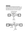
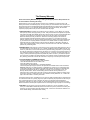
TCCI Block Diagram
Everything but
Kenwood
TX
RS232
radio
RX
levels
pc
level
shifting
radio
TX
Kenwo
od
RX
inverters
RS232
levels
level
shifting
TCCI-1 • 4
pc
The block diagram shown is a very general interpretation of the J-Com
Transceiver control Computer. When a signal is sent from your computer it
is in binary (a logic 1 or 0). The binary signal is between 3 and 25 volts for a
logic 1 and between -3 and -25 volts for a logic 0. Your radio doesn’t use
such voltage levels, therefore a level shifter is used to change these voltage
levels to something that it can deal with. A logic 1 is shifted to become
between 3.2 and 5 volts and a logic 0 is shifted to become between 0 to 2.4
volts. A Kenwood i different than other radios though,in that it require the
data to be inverted.
PARTS LIST
❒
❒
Software Disk
Cable with appropriate connectors
INSTALLATION:
Please understand that you must possess a basic computer “literacy” for the
following instructions. If you have trouble, your local computer or amateur
radio club can be quite helpful in explaining terms and the intricacies of your
individual computing system, including any software “glitches” that you
encounter while installing this interface.
❒
1. Turn off the AC power to both the transceiver and the computer.
❒
2. Plug the DB-25 connector into the desired COMM port of the
computer.
❒
3. Plug the transceiver connector into the appropriate jack on the back
of your transceiver. Consult the transceiver manuals if you are unsure
which is the correct jack.
TCCI-1 • 5
SOFTWARE:
The J-Comm Transceiver Control Computer Interface is compatible with all
rig control software available. This includes Kenwood’s HamWindows®,
DXBase, K1EA CT, LOGic, NA, TurboLog, Hyperlog, RC-Plus and many
others. Consult the software manual and any other on-disk information
(READ.ME files) which came with your software to understand how to
properly configure it to communicate with your radio. Many software
programs have different recommendations regarding the setting of these
parameters.
1. Select the appropriate serial port: COMM 1,2,3,... These may be
referred to as serial ports, comm ports or asynchronous
communications adapters in your software manual.
❒ 2. Set the serial interface parameters : base address and interrupt
request line (IRQ). You may need to tell the software how to access the
serial port on your computer.
❒ 3. Tell the software the brand and model of radio you are using. In most
cases, the software will determine the following parameters
automatically from its own data base of radio standards. If you are
having trouble, check the ASCII interface parameter: Baud rate, number
of data bits, parity, and number of stop bits. The radio and computer
must use the same standard in order to communicate. Consult your
radio manual first to determine the appropriate data transfer standard.
Some radios allow these parameters to be modified by setting the DIP
switches to internally. If you experience problems, verify that the
switches are set to the default positions. Consult your software manual
to determine how to set these parameters in the program.
❒
A note from us at J-COM:
We want to help you make sure that everything is working on the J-COM
interface cables before we see perfectly good interfaces coming back to be
repaired. Many of the other programs on this included disk turn out to be
only DEMOS. This means that many of them don't even try to communicate
to your radio, you need to register the program first! This depends mostly
on radio you have since some programs for other radios are fully functional.
Please read the readme files before jumping to conclusions!
RC-PLUS
TCCI-1 • 6
We have included a copy of the RC-Plus shareware radio control program
on our HamBase demo diskette. This program will be found in the directory
\RCPLUS. To use the program, copy all the files in the directory to your hard
disk, or to a different disk by typing :
C:> MD RCPLUS
C:> CD RCPLUS
C:>COPY A:\RCPLUS\*.*
(If copying from A drive, type COPY B ....,
if copying from B drive, type COPY A ....)
To print the document type:
C:>\RCPLUS>PRINT RCPLUS>DOC
To run the program type:
C:>\RCPLUS>RCPLUS
F1 will give you outline help.
ALT-S will allow you to specify your radio.
If you have trouble uderstanding the above, we suggest that you contact a
local computer user to help you.
TROUBLESHOOTING:
If the interface appears not to be working, here are some things to try:
❒
1. If the interface controls the radio in any way rest assured that it is
operating correctly and a software bug is to blame.This means that the
cable is not at fault.
❒
2. Check all connections for proper fit.
❒
3. Check that the correct radio is selected in your software.
❒
4.Check the serial port and it’s properties.
❒
5. Check the radio parameters and DIP switches (if any).
❒
6. Remove any TSRs that may conflict with your serial ports.
❒
7.Try using a different serial port.
❒
8. If you have more than two serial ports on your computer, check for
IRQ conflicts.
TCCI-1 • 7
Remember that the person with the most knowledge of your computer
system is you. We wish we could be more helpful, but it is virtually
impossible for us to debug your entire system on the telephone. The
majority of problems encountered are software setup related, i.e.
wrong COMM port, IRQ conflicts. Since we did not setup your system,
it is unadvisable for us to recommend that you change your system
settings. Please only call as a last resort and consult the warranty
procedure before doing so.
TESTING YOUR INTERFACE:
Connect the radio as you normally would to a power supply, connect the
interface cable to a communications port of your computer (COM1 or
COM2), and connect the other end to the radio. If needed, remove your
modem or other device to allow you to temporarily use one of these ports to
test your interface. These ports tend to be more standardized than COM3 or
COM4, so the program was not written to include the diversity of options
available. Now run the program by typing in the following commands at the
default prompt.
A:\COMMTEST.EXE (Where A is the drive that the install disk is in)
After making sure everything is set to go, look in your radio's manual under
computer control. There should be a good general description of the codes
required to perform certain tasks, data protocols (ie. , 4800, N, 8, 1) and so
on.
Look up the protocol first, and then set it in Commtest by pressing "S" on the
main menu. Follow the directions and answer the questions for baud rates,
stop bits, etc. Then look up a simple code like setting the frequency or
turning some feature on and off. Depending on how the manufacturer has
set up the op codes in the radio will determine what format to use. For
example the Yeasu 2.5200 Mhz, the op code needed is 0Ah, 01h, 42h, 50h,
00h. Note that 0Ah is the op code for setting frequency. The problem that
you will find upon trying to send this code to the radio is that it needs to be
sent in reverse order of what makes sense to you and me. The Yeasu FT900 radio requires that the codes be sent out in reverse order, so when
entered into the program you will need to start with 00h and end with the
code of 0Ah.
TCCI-1 • 8
To enter these codes into the program, press “O” on the main menu, then
choose the type of data transfer you require. In the case of the Yeasu FT900, you would choose “Enter Hex”. Now you can enter your code in, and in
case of the Yeasu and possibly others, enter the code in reverse.
Now you can press "1" or "2" on the main menu depending on which comm
port you are using. If you accidently press the comm port where your mouse
is running, it may disable your mouse temporarily until you restart another
program. Watch carefully on the radio to see if anything happens when you
transmit this data through the interface.
If the radio is receiving the data it means that your interface cable is
operating properly. If the display shows that it is receiving the data, but no
action occurs, check the op code you are using to make sure it is being
entered in the correct order, as well as the correct op code. If so, check
your comm specs again.
Naxt try to send out a code that returns some information-such as to
retrieve the operating frequency. This will help to verify that your receive
data line is operational also. Set up the comm specs as before and then
enter an op code that returns data. Now Comm test should show you the
data it has received after sending out the op code. If you are able to receive
something, rejoice, everything should work for you. If not, you will want to
check everything out, such as; your wiring, certain functions being enabled
on the radio, the correct op codes being used, and so on. If you are still
having trouble, have a fellow computer wiz help you out, maybe there is
something you missed.
Also note that not all radios send back their information in ASCII type code.
Most of the information they send back is encoded information, which when
displayed on the screen will look like Greek to most of us. You don't really
need to decode the information unless you are really expecting ASCII and
did not get it. If that is the case, you may wish to check the clock speeds of
your radio or computer, either that or turn the computer off, and then on
again to reset the serial ports. This is a problem beyond the scope of the
interface cable and the solution is in your existing hardware.
TCCI-1 • 9
The Ramsey Warranty
Please read carefully BEFORE calling or writing in about your product. Most problems can
be solved without contacting the factory.
Notice that this is not a "fine print" warranty. We want you to understand your rights and ours to! All
Ramsey kits will work if assembled properly. The very fact that your kit includes this new manual is your
assurance that a team of knowledgeable people have field-tested several "copies" of this kit straight from
the Ramsey Inventory. If you need help, please read through your manual carefully, all information
required to properly build and test your kit is contained within the pages!
1. DEFECTIVE PARTS: It's always easy to blame a part for a problem in your kit, Before you conclude
that a part may be bad, thoroughly check your work. Today's semiconductors and passive components
have reached incredibly high reliability levels, and its sad to say that our human construction skills have
not! But on rare occasion a sour component can slip through. All our kit parts carry the Ramsey
Electronics Warranty that they are free from defects for a full ninety (90) days from the date of
purchase. Defective parts will be replaced promptly at our expense. If you suspect any part to be
defective, please mail it to our factory for testing and replacement. Please send only the defective part
(s), not the entire kit. The part(s) MUST be returned to us in suitable condition for testing. Please be
aware that testing can usually determine if the part was truly defective or damaged by assembly or
usage. Don't be afraid of telling us that you 'blew-it', we're all human and in most cases, replacement
parts are very reasonably priced.
2. MISSING PARTS: Before assuming a part value is incorrect, check the parts listing carefully to see if it
is a critical value such as a specific coil or IC, or whether a RANGE of values is suitable (such as "100
to 500 uF"). Often times, common sense will solve a mysterious missing part problem. If you're missing
five 10K ohm resistors and received five extra 1K resistors, you can pretty much be assured that the '1K
ohm' resistors are actually the 'missing' 10 K parts ("Hum-m-m, I guess the 'red' band really does look
orange!") Ramsey Electronics project kits are packed with pride in the USA. If you believe we packed
an incorrect part or omitted a part clearly indicated in your assembly manual as supplied with the basic
kit by Ramsey, please write or call us with information on the part you need and proof of kit purchase
3. FACTORY REPAIR OF ASSEMBLED PRODUCT:
To qualify for Ramsey Electronics factory repair, kits MUST:
1. NOT be assembled with acid core solder or flux.
2. NOT be modified in any manner.
3. BE returned in fully-assembled form, not partially assembled.
4. BE accompanied by the proper repair fee. No repair will be undertaken until we have received the
MINIMUM repair fee (1 hour labor) of $36.00, or authorization to charge it to your credit card account.
5. INCLUDE a description of the problem and legible return address. DO NOT send a separate letter;
include all correspondence with the unit. Please do not include your own hardware such as nonRamsey cabinets, knobs, cables, external battery packs and the like. Ramsey Electronics, Inc.,
reserves the right to refuse repair on ANY item in which we find excessive problems or damage due to
construction methods. To assist customers in such situations, Ramsey Electronics, Inc., reserves the
right to solve their needs on a case-by-case basis.
The repair is $36.00 per hour, regardless of the cost of the kit. Please understand that our technicians are
not volunteers and that set-up, testing, diagnosis, repair and repacking and paperwork can take nearly an
hour of paid employee time on even a simple kit. Of course, if we find that a part was defective in
manufacture, there will be no charge to repair your kit (But please realize that our technicians know the
difference between a defective part and parts burned out or damaged through improper use or assembly).
4. REFUNDS: You are given ten (10) days to examine our products. If you are not satisfied, you may
return your unassembled kit with all the parts and instructions and proof of purchase to the factory for a
full refund. The return package should be packed securely. Insurance is recommended. Please do not
cause needless delays, read all information carefully.
TCCI-1 • 10
TCCI j·Com Transceiver Control Computer Interface
Quick Reference Page Guide
Introduction to the TCCI .............
TCCI Block Diagram ...................
Parts List ....................................
Instulation ...................................
Software .....................................
RC-Plus ......................................
Troubleshooting..........................
Testing Your Interface ................
TCCI Schematic Diagram ...........
Ramsey kit warranty ...................
4
4
5
5
6
7
8
8
10
11
Price: $5.00
Ramsey Publication No. MTCCI
Assembly and Instruction manual for:
RAMSEY MODEL NO. TCCI
j·Com Tansceiver Control Computer Interface
RAMSEY ELECTRONICS, INC.
793 Canning Parkway
Victor, New York 14564
Phone (716) 924-4560
Fax (716) 924-4555
Printed on recycled
TCCI-1 • 11