1
ATL SuperLoader™ DLT and ATL
SuperLoader™ LTO
Software Interface
Guide
81-60220-01 A02
Quantum ATL SuperLoader DLT and ATL SuperLoader LTO Software Interface Guide, 81-60220-01 A02,
March 2003. Made in USA.
Quantum Corporation provides this publication “as is” without warranty of any kind, either express or
implied, including but not limited to the implied warranties of merchantability or fitness for a particular
purpose. Quantum Corporation may revise this publication from time to time without notice.
COPYRIGHT STATEMENT
© 2003 Quantum Corporation. All rights reserved.
Your right to copy this manual is limited by copyright law. Making copies or adaptations without prior
written authorization of Quantum Corporation is prohibited by law and constitutes a punishable violation of
the law.
TRADEMARK STATEMENT
DLTtape, Super DLTtape, the Super DLTtape logo, and SuperLoader are trademarks, and Quantum and the
Quantum logo are registered trademarks, of Quantum Corporation.
Other trademarks are the property of their respective owners.
6207947-00cN 98
Contents
Intended Audience...............................................................................xv
Purpose .................................................................................................xvi
Organization.........................................................................................xvi
Document Conventions .................................................................... xvii
Chapter 1
Theory of Operation
1
SuperLoader DLT ................................................................................... 2
SuperLoader LTO ................................................................................... 2
Medium Changer Elements .................................................................. 2
Medium Transport Element ........................................................... 3
Data Transfer Element..................................................................... 3
Storage Elements.............................................................................. 3
Events ....................................................................................................... 3
Power Cycle ...................................................................................... 4
SuperLoader Offline ........................................................................ 4
Magazine Insertion/Removal ........................................................ 4
Maximum Temperature Exceeded ................................................ 5
Automatic Drive Cleaning .................................................................... 5
Element Status Information............................................................ 6
Automatic Cleaning Operation...................................................... 6
Quantum ATL SuperLoader Software Interface Guide
iii
Chapter 2
Messages
9
Message Format ......................................................................................9
Supported SCSI Messages ...................................................................13
Abort (06h) ......................................................................................13
Bus Device Reset (0Ch)..................................................................13
Command Complete (00h) ...........................................................14
Disconnect (04h) ............................................................................14
Identify (80h-FFh) ..........................................................................15
Ignore Wide Residue (23h) ...........................................................16
Initiator Detected Error (05h) .......................................................17
Linked Command Complete (0Ah).............................................18
Linked Command Complete, Flag (0Bh)...................................19
Message Parity Error (09h) ...........................................................19
Message Reject (07h).....................................................................19
No Operation (08h) ........................................................................20
Restore Pointers (03h)....................................................................20
Save Data Pointer (02h) .................................................................20
Synchronous Data Transfer Request (01h) .................................21
Wide Data Transfer Request Extended Message (03h) ............23
Chapter 3
Media Changer Commands
27
Overview of Command and Status Processing................................27
Media Changer Command Descriptions ..........................................29
Initialize Element Status Command (07h) ........................................31
Inquiry Command (12h) ......................................................................32
Standard Inquiry Data Page .........................................................33
Vital Product Data Page ................................................................38
Command Support Data...............................................................42
Load Unload Command (1Bh) ...........................................................45
Log Sense Command (4Dh) ................................................................46
Supported Pages Log Page (Page 00h)........................................49
Last n Error Events Page (07h).....................................................50
TapeAlert Page (2Eh).....................................................................52
Move Statistics Page (30h) ............................................................54
Hard/Soft Error Statistics Page (31h) .........................................56
Device Wellness Page (33h) ..........................................................59
Device Status Page (3Eh)...............................................................62
iv
Quantum ATL SuperLoader Software Interface Guide
Mode Select (6) / (10) Command (15h / 55h) .................................. 66
Mode Parameter List ..................................................................... 68
Mode Sense (6) / (10) Command (1Ah/ 5Ah) ................................. 74
Mode Sense Data Headers............................................................ 76
Mode Sense Mode Pages............................................................... 78
TapeAlert Page (1Ch) .................................................................... 79
Element Address Assignment Page ............................................ 82
Transport Geometry Parameters Page........................................ 85
Device Capabilities Page............................................................... 86
Move Medium Command (A5h)........................................................ 89
Persistent Reserve In Command (5Eh).............................................. 91
Persistent Reserve Out Command (5Fh)......................................... 101
Position to Element Command (2Bh) .............................................. 116
Prevent/Allow Medium Removal (1Eh) ........................................ 118
Read Buffer Command (3Ch) ........................................................... 120
Combined Header and Data Mode (000b) ............................... 122
Data Mode (0010b)....................................................................... 123
Descriptor Mode (0011b)............................................................. 123
Read Data from Echo Buffer (1010b)......................................... 123
Echo Buffer Descriptor Mode (1011b)....................................... 124
Read Element Status Command (B8h) ............................................ 126
Element Status Data..................................................................... 128
Element Status Page .................................................................... 130
Medium Transport Element Descriptor ................................... 131
Storage Element Descriptor........................................................ 134
Import/Export Element Descriptor .......................................... 135
Data Transfer Element Descriptor............................................. 137
Release Element (10) Command (57h)............................................. 140
Release Unit (6) Command (17h) ..................................................... 143
Report Device Identifier Command (A3h) ..................................... 145
Report LUNS Command (A0h) ........................................................ 148
Request Sense Command (03h) ........................................................ 151
Reserve Element (10) Command (56h)............................................ 160
Reserve Element (6) Command (16h).............................................. 163
Send Diagnostic Command (1Dh) ................................................... 166
Set Device Identifier Command (A4h) ............................................ 168
Test Unit Ready Command (00h)..................................................... 170
Quantum ATL SuperLoader Software Interface Guide
v
Write Buffer Command (3Bh)...........................................................171
Write Combined Header and Data Mode (0000b) ..................172
Write Data Mode (0010b) ............................................................172
Download Microcode Mode (0100b).........................................173
Download Microcode and Save Mode (0101b)........................173
Write Data to Echo Buffer (1010b) .............................................173
vi
Quantum ATL SuperLoader Software Interface Guide
Figures
Figure 1
Extended Message ............................................................ 12
Figure 2
Identify Message ............................................................... 15
Figure 3
Ignore Wide Residue Message........................................ 17
Figure 4
Synchronous Data Transfer Request Message ............. 21
Figure 5
Wide Data Transfer Request Message ........................... 24
Figure 6
Initialize Element Status Command .............................. 31
Figure 7
Inquiry Command ............................................................ 32
Figure 8
Inquiry Command ............................................................ 33
Figure 9
Standard Inquiry Data (LTO).......................................... 34
Figure 10 Standard Inquiry Data (DLT).......................................... 35
Figure 11 Supported Vital Product Data......................................... 39
Figure 12 Unit Serial Number Page (80h) ....................................... 39
Figure 13 Device Identification Page (83h)..................................... 40
Figure 14 Identifier Descriptor ......................................................... 41
Figure 15 Command Support Data Page ........................................ 43
Figure 16 Load Unload Command Descriptor Block.................... 45
Quantum ATL SuperLoader Software Interface Guide
vii
Figure 17 LOG SENSE Command Descriptor Block .....................46
Figure 18 Supported Pages Page......................................................49
Figure 19 Last n Error Events Log Sense Header ..........................50
Figure 20 Format for Last n Error Events Log Sense.....................51
Figure 21 TapeAlert Log Sense Header Format.............................52
Figure 22 TapeAlert Page Log Parameters Format .......................53
Figure 23 Move Statistics Format .....................................................54
Figure 24 Hard/Soft Move Error Statistics Format.......................57
Figure 25 Device Wellness Log Sense Header ...............................59
Figure 26 Device Wellness Log Sense (0000h-000Fh)....................60
Figure 27 Log Parameters for Device Wellness Log Sense...........61
Figure 28 Device Status Log Sense Header ....................................62
Figure 29 Parameters for Device Status Log Sense Page ..............63
Figure 30 Device Status Log Sense Page (0001h) ...........................64
Figure 31 Mode Select (6) Command Descriptor...........................67
Figure 32 Mode Select (10) Command Descriptor.........................67
Figure 33 Mode Select (6) Mode Parameter List ............................68
Figure 34 Mode Select (10) Mode Parameter List ..........................69
Figure 35 Mode Select (6) Parameter Header.................................70
Figure 36 Mode Select (10) Parameter Header...............................70
Figure 37 Mode Select Parameter.....................................................71
Figure 38 Mode Select Page Descriptor...........................................72
Figure 39 Mode Sense (6) Command Descriptor Block ................74
Figure 40 Mode Sense (10) Command Descriptor Block ..............75
Figure 41 Mode Sense (6) Data Header...........................................77
Figure 42 Mode Sense (10) Data Header.........................................77
Figure 43 Mode Sense Page Descriptor...........................................78
viii
Quantum ATL SuperLoader Software Interface Guide
Figure 44 TapeAlert Page Format Descriptor ................................ 79
Figure 45 Element Address Assignment Page ............................... 83
Figure 46 Transport Geometry Parameters Page........................... 85
Figure 47 Transport Geometry Descriptor ..................................... 86
Figure 48 Device Capabilities Page.................................................. 87
Figure 49 Move Medium Descriptor Block .................................... 89
Figure 50 Persistent Reserve In Descriptor Block.......................... 91
Figure 51 Read Keys Parameters...................................................... 93
Figure 52 Read Reservations Parameters........................................ 95
Figure 53 Persistent Reserve In Read Reservations....................... 97
Figure 54 Persistent Reserve Out Descriptor ............................... 102
Figure 55 Persistent Reserve Out Command ............................... 102
Figure 56 Persistent Reserve Out Parameter List ........................ 112
Figure 57 Position to Element Descriptor ..................................... 116
Figure 58 Prevent/Allow Medium Removal ............................... 118
Figure 59 Read Buffer Command Descriptor Block .................... 120
Figure 60 Read Buffer Header ........................................................ 122
Figure 61 Read Buffer Descriptor................................................... 123
Figure 62 Echo Buffer Descriptor................................................... 124
Figure 63 Read Element Status Descriptor ................................... 126
Figure 64 Element Status Data Header ......................................... 128
Figure 65 Element Status Page ....................................................... 130
Figure 66 Data ................................................................................... 131
Figure 67 Medium Transport Element Descriptor ...................... 132
Figure 68 Storage Element Descriptor........................................... 134
Figure 69 Import/Export Element Descriptor ............................. 136
Figure 70 Data Transfer Element Descriptor................................ 138
Quantum ATL SuperLoader Software Interface Guide
ix
Figure 71 Release (10) Descriptor Block ........................................140
Figure 72 Release (10) ID Only Parameter List ............................142
Figure 73 Release Unit (6) Descriptor Block (LTO) .....................143
Figure 74 Release Unit (6) Descriptor Block (DLT) .....................144
Figure 75 Report Device Identifier Descriptor .............................145
Figure 76 Report Device Identifier.................................................146
Figure 77 Report LUNS Descriptor................................................148
Figure 78 LUN Reporting Parameter List .....................................149
Figure 79 Request Sense Command Descriptor Block ................151
Figure 80 Request Sense Command Data .....................................151
Figure 81 Request Sense ..................................................................152
Figure 82 Reserve Element (10) Descriptor ..................................160
Figure 83 Reserve (10) ID Only Parameter List............................162
Figure 84 Reserve Element (6) Descriptor (LTO).........................163
Figure 85 Reserve Element (6) Descriptor (DLT).........................164
Figure 86 Send Diagnostic Descriptor ...........................................166
Figure 87 Set Device Identifier Descriptor....................................168
Figure 88 Set Device Identifier Parameter List.............................169
Figure 89 Test Unit Ready Descriptor ...........................................170
Figure 90 Write Buffer Descriptor..................................................171
x
Quantum ATL SuperLoader Software Interface Guide
Tables
Table 1
Message Format ................................................................ 10
Table 2
Supported Messages......................................................... 10
Table 3
Extended Message ............................................................ 12
Table 4
Response to Disconnect Message ................................... 15
Table 5
Identify Message ............................................................... 16
Table 6
Ignore Wide Residue ........................................................ 17
Table 7
Response to Initiator Detected Error.............................. 18
Table 8
Transfer Rates.................................................................... 23
Table 9
Supported Media Changer Commands ........................ 28
Table 10
Standard Inquiry Data (LTO and DLT) ......................... 36
Table 11
Unit Serial Number Page Field Descriptions................ 40
Table 12
Identifier Descriptor Field Descriptions........................ 41
Table 13
Supported Identifiers ....................................................... 42
Table 14
Command Support Data Page ........................................ 43
Table 15
Unload Command Descriptor Block.............................. 45
Table 16
Log Sense Command Descriptor Block ......................... 47
Quantum ATL SuperLoader Software Interface Guide
xi
xii
Table 17
Last n Error Events Log Sense Header ..........................50
Table 18
Parameters Last n Error Events Log Sense....................51
Table 19
TapeAlert Log Sense Header Field Descriptions .........53
Table 20
TapeAlert Page Log Parameters .....................................54
Table 21
Move Statistics...................................................................56
Table 22
Hard/Soft Error ................................................................58
Table 23
Device Wellness Log Sense Header ...............................59
Table 24
Device Status Log Sense Header ....................................63
Table 25
Parameters for Device Status Log Sense Page ..............63
Table 26
Device Status Log Sense (0001h).....................................65
Table 27
Mode Select (6)/(10) Command Descriptor..................68
Table 28
Mode Select Parameter List .............................................69
Table 29
Mode Select Parameter Header ......................................71
Table 30
Mode Select Parameter Block..........................................72
Table 31
Mode Select Page Descriptor...........................................73
Table 32
Mode Sense Command Descriptor Block......................75
Table 33
Mode Sense Data Heade ..................................................78
Table 34
Mode Sense Page Descriptor...........................................79
Table 35
TapeAlert Page Format Descriptor ................................80
Table 36
Element Address Assignment Page ...............................84
Table 37
Transport Geometry Parameters Page...........................86
Table 38
Device Capabilities Page..................................................88
Table 39
Move Medium Command ...............................................90
Table 40
Persistent Reserve In Command.....................................92
Table 41
Read Keys Parameters......................................................94
Table 42
Read Reservations Parameters........................................96
Table 43
Persistent Reserve In Read Reservations Descriptor ...97
Quantum ATL SuperLoader Software Interface Guide
Table 44
Persistent Reservation Type Codes................................ 99
Table 45
Persistent Reserve Out Command Service Action..... 105
Table 46
Persistent Reservation Type Codes.............................. 110
Table 47
Persistent Reserve Out Parameter List ........................ 113
Table 48
Device Server Interpretation of Service and Scope
Value ................................................................................. 115
Table 49
Position to Element Command ..................................... 117
Table 50
Prevent/Allow Medium Removal Command
Descriptor Block.............................................................. 119
Table 51
Read Buffer Command Descriptor Block .................... 121
Table 52
Read Buffer Header ........................................................ 122
Table 53
Echo Buffer Descriptor................................................... 125
Table 54
Read Element Status Command Descriptor Block..... 127
Table 55
Element Status Data ....................................................... 129
Table 56
Medium Transport Element Descriptor ...................... 133
Table 57
Storage Element Descriptor........................................... 135
Table 58
Import/Export Element Descriptor ............................. 137
Table 59
Data Transfer Element Descriptor................................ 139
Table 60
Release (10) Command................................................... 141
Table 61
Report Device Identifier Command Descriptor
Block.................................................................................. 146
Table 62
Report Device Identifier Parameter Data .................... 147
Table 63
Report LUNS Command Descriptor Block ................. 149
Table 64
Request Sense Data......................................................... 153
Table 65
Supported Sense Keys for Request Sense.................... 155
Table 66
Supported ASC / ASCQ (Hex) for Request Sense..... 156
Table 67
Reserve Element (10) Command .................................. 161
Table 68
Send Diagnostic Command Data ................................. 166
Quantum ATL SuperLoader Software Interface Guide
xiii
xiv
Table 69
Set Device Identifier Command Descriptor Block .....169
Table 70
Set Device Identifier Parameter List.............................169
Table 71
Write Buffer Command Data ........................................172
Quantum ATL SuperLoader Software Interface Guide
Preface
This section outlines the scope and contents of the Quantum ATL
SuperLoader™ Software Interface Guide. It contains information
about the intended audience, purpose, organization, and
document conventions.
Intended Audience
0
This interface guide is a written for the following audiences:
•
Original Equipment Manufacturers (OEMs) that integrate the
Quantum ATL SuperLoader into a system or subsystem
•
System integrators that are responsible for the SCSI interface
•
End users that operate and troubleshoot the SuperLoader
Quantum ATL SuperLoader Software Interface Guide
xv
Preface
Purpose
Purpose
0
This interface guide describes the procedures and issues involved
in the development of software applications and utilities to
communicate with the Quantum ATL SuperLoader.
•
SCSI interfaces
•
SCSI Messages
•
Media Changer Commands
Organization
0
This reference manual is organized as follows:
xvi
•
Chapter 1, Theory of Operation describes differences between
the SuperLoader models, media changer elements, events, and
automatic drive cleaning.
•
Chapter 2, Messages describes the SCSI messages supported by
the SuperLoader.
•
Chapter 3, Media Changer Commands describes the SCSI
protocol features implemented in the media changer.
Quantum ATL SuperLoader Software Interface Guide
Preface
Document Conventions
Document Conventions
0
This manual uses the following conventions to designate specific
elements:
Element
Convention
Example
Abbreviations
Lowercase, except where standard usage
requires uppercase
Mb (megabits)
MB (megabytes)
Acronyms
Uppercase
SCSI
Binary Notation
Number followed by lowercase b
101b
Commands
Uppercase (unless case-sensitive)
FORMAT UNIT
Decimal Notation
Number followed without suffix
101
Field
Initial Caps (unless case-sensitive)
Application Data
Hexadecimal Notation
Number followed by h
101h
Sense Key
Uppercase (unless case-sensitive)
ILLEGAL REQUEST
Quantum ATL SuperLoader Software Interface Guide
xvii
Preface
Document Conventions
xviii
Quantum ATL SuperLoader Software Interface Guide
Chapter 1
1
Theory of Operation
The SuperLoader products are an integration of two separate
devices, a tape drive and a media changer. The media changer
consists of all the mechanics and electronics required to store and
move tape cartridges while the tape drive provides the read/write
functionality.
Each device has a separate interface for communication to the host.
The SCSI command set supported by the tape drive is documented
separately. The SCSI command set supported by the media
changer device is detailed in xxx.
The SuperLoader is fully compliant with the ANSI SCSI-2 standard
for tape drive and media changer devices and implements many
optional features.
The SuperLoader does not act as an initiator on the SCSI bus.
Therefore, it does not generate unsolicited interrupts to the bus,
initiate its own SCSI commands, or assert bus reset.
Quantum ATL SuperLoader Software Interface Guide
1
Chapter 1 Theory of Operation
SuperLoader DLT
SuperLoader DLT
1
The SuperLoader DLT family of products utilize a single SCSI ID
and two logical units. The tape drive always resides at logical unit
0 and the media changer resides at logical unit 1. The SuperLoader
supports narrow and wide, synchronous and asynchronous data
transfers. Both LVD and single-ended versions are available.
SuperLoader LTO
1
The SuperLoader LTO family of products utilize two separate SCSI
IDs. The tape drive and media changer each reside on a unique ID.
The media changer device supports narrow and wide,
asynchronous data transfers only. The tape drive device supports
narrow and wide, synchronous and asynchronous data transfers.
Medium Changer Elements
1
The medium changer command set accesses the address space for
the set of physical locations and mechanisms with the
SuperLoader. This guide uses the SCSI-2 term element to refer to
one member of the SuperLoader address space. Each element is a
discrete physical entity that can hold a single tape cartridge. Each
element within a SuperLoader is represented by a unique 16-bit
element address. The SuperLoader consists of the following
medium changer elements.
2
•
Medium transport element
•
Storage elements
•
Data transfer elements
Quantum ATL SuperLoader Software Interface Guide
Chapter 1 Theory of Operation
Events
You can issue the Mode Sense command to determine the
SuperLoader configuration. You can also use this command to
determine the first address and the number of elements of each
type.
Although the SuperLoader does have a mailslot, it is not reported
as an Import/Export element for use by the host system. It is
strictly to allow users to access tape cartridges using the front
panel or On-board Remote Management tool.
Medium Transport
Element
1
This mechanism can hold a single cartridge and is considered a
single medium transport element. It is used to move media
between elements within the SuperLoader.
Data Transfer
Element
The SuperLoader is configured with a single tape drive.
1
Storage Elements1
All of the storage elements within the SuperLoader are contained
within removable magazines. There are two magazines which hold
eight tape cartridges each, for a total of 16 storage elements. Since
the magazines are removable, a user may insert or remove a
magazine at any time. Because of this, the SuperLoader always
reports 16 storage elements, regardless of how many magazines
are currently installed. When a magazine is removed, the
corresponding storage elements are reported as inaccessible. This
is done via the Read Element Status–Storage Element Descriptor
on page 134–byte 2, bit 3.
Events
1
Events are system conditions created y operator actions or system
failures. These events are recorded in sense data for the SCSI host
to retrieve via the Request Sense command.
Quantum ATL SuperLoader Software Interface Guide
3
Chapter 1 Theory of Operation
Events
Power Cycle
1
When the SuperLoader is powered-on, it goes through an
initialization sequence, during which it:
•
Resets and initializes all hardware
•
Responds to SCSI commands which do not require movement
•
Responds to Test Unit Read and all movement type comands
with a not ready, initialization in progress check condition
(SK=02 ASC=29 ASCQ=02).
When the power on initialization is complete, it:
SuperLoader
Offline
Magazine
Insertion/
Removal
1
1
•
Generates a Power On/Reset Occurred event (SK=6 ASC=29
ASCQ=02)
•
If initialization is sucessful, it generates a note ready to ready
transition (SK=6 ASC=28 ASCQ=00), otherwise, failure sense
data is set accordingly.
When a user accesses the SuperLoader via the front panel or Onboard Remote Management in such a way that would cause
conflict with a SCSI command, the SuperLoader is put into an
offline state. If a SCSI command is received while in this offline
state, a not ready check condition is reported (SK=01 ASC=04
ASCQ=07).
The SuperLoader must be powered-on with at least one magazine,
otherwise a check condition is reported (SK=-2 ASC=04
ASCQ=03).
While the system is online, the user may remove a magazine blank
and replace it with a magazine. The SuperLoader will calibrate the
newly installed magazine and check the presence of tape
cartridges in each of the storage elements. While this inventory is
in progress, the SuperLoader LTO will report a not ready check
condition (SK=02 ASC=04 ASCQ=01). The SuperLoader DLT does
not provide any indication that the operation is in progress. Once
the inventory is complete, all SuperLoaders report a unit attention
(SK=06 ASC=3B ASCQ=13).
4
Quantum ATL SuperLoader Software Interface Guide
Chapter 1 Theory of Operation
Automatic Drive Cleaning
Similarly, while a magazine is in the process of being removed, a
not ready check condition is reported (SK=02 ASC=04 ASCQ=07).
Once the operation is complete, by replacing the magazine with a
blank, a unit attention is reported (SK=06 ASC=3B ASCQ=12).
While one or both of the magazine bays are open, a not ready
check condition is reported (SK=02 ASC=04 ASCQ=03).
Maximum
Temperature
Exceeded
1
The SuperLoader monitors the ambient temperature within the
system. If the temperature exceeds the maximum safe temperature
for the media, the SuperLoader will disable all movement until the
temperature decreases below a safe threshold. While the
temperature remains excessive, SCSI commands that require
movement will fail (SK=04 ASC=0B ASCQ=01).
Automatic Drive Cleaning
1
There are two modes of automatic drive cleaning support
available:
•
Host-initiated cleaning
•
SuperLoader managed cleaning
Both modes provide automatic cleaning of the drive, but the first is
managed by the host and the second is managed by the
SuperLoader. These two modes are configured separately, and
only one should be enabled at any given time.
When automatic drive cleaning of the drive is enabled, either the
host of the SuperLoader is responsible for all cleaning functions
such as:
•
Detecting when a drive requires cleaning
•
Tracking and selecting cleaning cartridges
•
Moving a cleaning cartridge to the drive
Quantum ATL SuperLoader Software Interface Guide
5
Chapter 1 Theory of Operation
Automatic Drive Cleaning
•
Determining when a cleaning cartridge has used all of its
available cleaning cycles
By default, the SuperLoader is configured to allow for hostinitiated cleaning. If automatic cleaning is disabled from the host,
the SuperLoader can be configured to manage the automatic
cleaning of the drive. This is done by enabling the “Auto Clean”
function. Please refer to the Quantum ATL SuperLoader Automated
Tape Library User Manual for information on how this is done.
Note:
There is no way for the host and SuperLoader to know
how the other is configured with respect to automatic
drive cleaning. It is up to the user to make sure only one
is enabled.
In host-initiated cleaning mode, the host tracks all cleaning
cartridges and their use. When the SuperLoader Auto Clean
feature is enabled, a “cleaning slot” is allocated and the cleaning
cartridge is stored in this storage element. The SuperLoader
assumes that any cartridge stored in this location is a cleaning
cartridge and will attempt to use it as such.
The SuperLoader does not keep track of the number of times a
cleaning tape is used. Instead, it relies on the tape drive to report
when the tape has expired. When this happens, the superLoader
will notify the user via the front panel. The Auto Clean function is
automatically disabled until the user inserts a new cleaning tape
and re-enables the feature.
Element Status
Information
Automatic
Cleaning
Operation
6
1
1
When the SuperLoader Auto Clean feature is enabled, the
allocated storage element is reported as inaccessible to the host.
This is done by setting the access bit to 0 in the Read Element
Status Storage Element Descriptor page.
when the SuperLoader Auto Clean feature is enabled, the
SuperLoader checks if the drive needs cleaning after each
successful move from the drive. Therefore, each time the drive is
unloaded, it is checked.
Quantum ATL SuperLoader Software Interface Guide
Chapter 1 Theory of Operation
Automatic Drive Cleaning
The movement of the cleaning tape is handled differently
depending on the SuperLoader model.
SuperLoader DLT
1
If the move command, that unloaded the drive, was initiated from
SCSI, the cleaning tape is moved from its storage slot, to the drive,
the cleaning is performed and the cleaning tpae is returned to its
storage slot, before command complete status is returned to the
SCSI host. If an unrecoverable error occrus when moving a
cleaning cartridge that prevents a subsequent host initiated
command from completing, a check condition will be set in the
returned status byte and sense data is set appropriately.
SuperLoader LTO
1
If the move command that unloaded the drive was initiated from
SCSI, command complete is returned to the host when the move
completes. The cleaning tape is then moved from its storage slot to
the drive. The cleaning is performed and once complete, the
cleaning tape is returned to its stoage location. If a SCSI command
is received during this cleaning process, a not ready check
condition is reported (SK=-2 ASC=30 ASCQ=03).
Quantum ATL SuperLoader Software Interface Guide
7
Chapter 1 Theory of Operation
Automatic Drive Cleaning
8
Quantum ATL SuperLoader Software Interface Guide
Chapter 2
2
Messages
The SCSI message system allows communication between an
initiator and the SuperLoader for interface management and
command qualification. Messages can be originated by either the
initiator or the SuperLoader. This section contains a detailed
description of the messages supported by the SuperLoader.
Message Format
2
A message can be one or more bytes in length. One or more
messages can be sent during a single MESSAGE phase, but a
message cannot be split over MESSAGE phases. The initiator is
required to end the MESSAGE OUT phase (by negating ATN)
when it sends certain messages that are identified in table 1.
When a connection to the SuperLoader is established, for example
the SuperLoader is selected with ATN asserted, the first message
byte passed by the initiator must be either an IDENTIFY, ABORT,
or BUS DEVICE RESET message. If not, the SuperLoader discards
the message, saves no status information, and goes to the BUS
FREE phase.
Quantum ATL SuperLoader Software Interface Guide
9
Chapter 2 Messages
Message Format
If an initiator supplies an unsupported message, for example,
COMMAND COMPLETE or a reserved or undefined message
code, the SuperLoader returns a MESSAGE REJECT message and
continues where it left off, possibly returning to MESSAGE OUT if
ATN is raised.
The first byte of the message, as defined in table 1, determines the
format of the message.
Table 1 Message
Format
Message Code
Message
00h
One-byte message (COMMAND COMPLETE)
01h
Extended message
02h – 1Fh
One-byte message
20h – 2Fh
Two-byte message
40h – 7Fh
Reserved
80h – FFh
One-byte message (IDENTIFY)
The SuperLoader supports the messages listed in table 2. The
message code and the direction of the message flow is also
included in the table (In = target to initiator, Out = initiator to
target).
Table 2 Supported
Messages
10
Message
Message Code
ABORT
06h
Out
BUS DEVICE RESET
0Ch
Out
COMMAND COMPLETE
00h
In
DISCONNECT
04h
In
Quantum ATL SuperLoader Software Interface Guide
Direction
Out
Chapter 2 Messages
Message Format
Message
Message Code
Direction
EXTENDED MESSAGE
(Synchronous Data and Wide
Data Transfer Requests) *
01h
In
Out
IDENTIFY
80h – FFh
In
Out
IGNORE WIDE RESIDUE
23h
In
INITIATOR DETECTED
ERROR
05h
LINKED COMMAND
COMPLETE
0Ah
In
LINKED COMMAND
COMPLETE (with flag)
0Bh
In
MESSAGE PARITY ERROR
09h
MESSAGE REJECT
07h
NO OPERATION
08h
RESTORE POINTERS
03h
In
SAVE DATA POINTER
02h
In
*
Out
Out
In
Out
Out
Extended message (figure 1).
Two-byte messages consist of two consecutive bytes. The value of
the first byte, as defined in table 1, determines which message is to
be transmitted. The second byte is a parameter byte that is used as
defined in the message description.
A value of 1 in the first byte indicates the beginning of a multiplebyte extended message. The minimum number of bytes sent for an
extended message is three. The extended message format is shown
in figure 1 and the data fields are described in table 3.
Quantum ATL SuperLoader Software Interface Guide
11
Chapter 2 Messages
Message Format
Figure 1 Extended
Message
Bit
Byte
7
6
5
4
3
0
Extended Message (01h)
1
Extended Message Length
2
Extended Message Code
3 to
n-1
2
1
0
Extended Message Arguments
Table 3 Extended
Message
Field
Description
Extended Message
Length
This field specifies the length, in bytes, of the Extended Message
Code plus the Extended Message Arguments that follow.
Therefore, the total length of the message is equal to the Extended
Message Length plus 2.
A value of 0 for the Extended Message Length indicates that 256
bytes follow.
Extended Message Code
The SuperLoader supports the following Extended Messages:
01h SYNCHRONOUS DATA TRANSFER REQUEST
03h WIDE DATA TRANSFER REQUEST
12
Quantum ATL SuperLoader Software Interface Guide
Chapter 2 Messages
Supported SCSI Messages
Supported SCSI Messages
2
Following are descriptions of each of the messages supported by
the SuperLoader.
Abort (06h)
2
This message is sent from the initiator to the target to clear the
current I/O process on the selected unit. The target goes directly to
the BUS FREE phase after successful receipt of this message.
Current settings of MODE SELECT parameters and reservations
are not affected. Commands, data, and status for other initiators
are not affected.
This message can be sent to a logical unit that is not currently
performing an operation for the initiator. If no unit has been
selected, the target goes to BUS FREE phase and no commands,
data, or status on the target are affected.
If a command that causes movement of the media changer has
started, the movement will complete and STATUS will not be sent
to the initiator.
Bus Device Reset
(0Ch)
2
The BUS DEVICE RESET message is sent from an initiator to direct
the SuperLoader to clear all I/O processes on the drive. The
message causes the SuperLoader to execute a hard reset, leaving it
as if a Bus Reset had occurred.
The SuperLoader creates a Unit Attention condition for all
initiators after accepting and processing a Bus Device Reset
message. The additional sense code is set to POWER ON, RESET,
or BUS DEVICE RESET OCCURRED.
If a command that causes movement of the media changer has
started, the movement will complete and STATUS will not be sent
to the initiator.
Quantum ATL SuperLoader Software Interface Guide
13
Chapter 2 Messages
Supported SCSI Messages
Command
Complete (00h)
2
Disconnect (04h) 2
The COMMAND COMPLETE message is sent by the SuperLoader
to an initiator to indicate that an I/O process has completed and
that valid status has been sent to the initiator. After successfully
sending this message, the SuperLoader goes to the BUS FREE
phase by releasing the BSY signal. The SuperLoader considers the
message transmission successful when it detects the negation of
ACK for the COMMAND COMPLETE message with the ATN
signal false. If a COMMAND COMPLETE message is received by
the SuperLoader, it is handled as an illegal message: the
SuperLoader returns MESSAGE REJECT and enters its STATUS
phase, reporting CHECK CONDITION with the sense key set to
COMMAND ABORTED.
The DISCONNECT message is sent from the SuperLoader to
inform the initiator that the present connection is going to be
broken, such as the SuperLoader plans to disconnect by releasing
the BSY signal, and a later reconnect will be required to complete
the current I/O process. The message does not cause the initiator
to save the data pointer. After sending the message, the
SuperLoader goes to the BUS FREE phase by releasing the BSY
signal.
The DISCONNECT message can also be sent by the initiator to tell
the SuperLoader to suspend the current phase and disconnect
from the bus. The SuperLoader’s response to and its handling of a
DISCONNECT message are based on when, in the I/O process, the
initiator introduces the DISCONNECT message. Table 7
summarizes the SuperLoader’s response.
14
Quantum ATL SuperLoader Software Interface Guide
Chapter 2 Messages
Supported SCSI Messages
Table 4 Response to
Disconnect Message
BUS Phase
SuperLoader Response
SELECTION
The SuperLoader discards the DISCONNECT message and goes to BUS
FREE.
COMMAND
The SuperLoader discards the DISCONNECT message and goes to BUS
FREE. The ATTENTION request is ignored while the Command Descriptor
Block is fetched. The SuperLoader does not switch to MESSAGE OUT until
the current DMA completes.
DATA
The ATTENTION request is ignored while the current data transfer
completes; that is, the SuperLoader does not switch to MESSAGE OUT
until after the current DMA completes. The SuperLoader returns a
MESSAGE REJECT message and responds with CHECK CONDITION
status, indicating the command aborted because of an invalid message.
STATUS
The SuperLoader sends a MESSAGE REJECT message, then sends
COMMAND COMPLETE.
MESSAGE IN
The SuperLoader sends a MESSAGE REJECT message and switches to the
BUS FREE phase.
The IDENTIFY message is sent by either the initiator or the
SuperLoader to establish or re-establish the physical connection
path between an initiator and target for a particular logical unit
under the conditions listed below. Figure 2 shows the format of the
IDENTIFY message and table 5 describes the data field contents.
Identify (80h-FFh)2
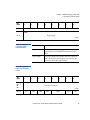
Figure 2 Identify
Message
Bit
7
6
5
4
Identify
DiscPriv
LUNTAR
Reserved
3
2
1
0
LUNTRN
Quantum ATL SuperLoader Software Interface Guide
15
Chapter 2 Messages
Supported SCSI Messages
Table 5 Identify
Message
Field
Description
Identify
The Identify bit must be set to 1. This identifies the message as an IDENTIFY
message.
DiscPriv
Disconnect Privilege. The DiscPriv can be 0, provided that no other I/O
process is currently active in the SuperLoader. If not set to 1 and other I/O
processes are currently active in the SuperLoader, the SuperLoader returns
BUSY status.
LUNTAR
The Logical Unit/Target Routine (LUNTAR) field must be set to zero. The
SuperLoader does not support target routines. A LUNTAR bit of one causes
the drive to send a MESSAGE REJECT message and switch to the BUS FREE
phase.
Reserved
The Reserved bits must be zero. If a Reserved bit is non-zero, the
SuperLoader returns a MESSAGE REJECT message and switches to the BUS
FREE phase.
LUNTRN
Logical Unit Number. The SuperLoader has two logical units. The tape
drive is always logical unit 0, and the media changer device is always logical
unit 1.
Ignore Wide
Residue (23h)
16
2
The IGNORE WIDE RESIDUE message is sent by the target to the
initiator to indicate that the number of valid bytes sent during the
last REQ/ACK handshake and REQB/ACKB handshake of a
DATA IN phase is less than the negotiated transfer width. The
Ignore field indicates the number of invalid data bytes transferred.
This message is sent immediately following that DATA IN phase
and prior to any other messages. Figure 3 illustrates the data
format of an IGNORE WIDE RESIDUE message. Table 6 describes
the Ignore field bit definitions.
Quantum ATL SuperLoader Software Interface Guide
Chapter 2 Messages
Supported SCSI Messages
Figure 3 Ignore Wide
Residue Message
Bit
Byte
7
6
5
4
3
0
Message Code (23h)
1
Ignore (01h)
Table 6 Ignore Wide
Residue
Initiator Detected
Error (05h)
2
2
1
Ignore
Invalid Data Bits (16-bit Transfers)
00h
Reserved
01h
DB(15-8)
02h - FFh
Reserved
0
The INITIATOR DETECTED ERROR message is sent from an
initiator to inform the SuperLoader that an error has occurred that
does not preclude the SuperLoader from retrying the operation (a
bus parity error, for example). The source of the error may either
be related to previous activities on the SCSI bus or may be only
SuperLoader-related. When received, the SuperLoader attempts to
re-transfer the last command, data, or status bytes by using the
RESTORE POINTER message mechanism.
The SuperLoader’s response to and its handling of an INITIATOR
DETECTED ERROR message are based on when, in the I/O
process, the initiator introduces the message. Table 7 summarizes
the SuperLoader’s response.
Quantum ATL SuperLoader Software Interface Guide
17
Chapter 2 Messages
Supported SCSI Messages
Table 7 Response to
Initiator Detected Error
BUS Phase
SuperLoader Response
SELECTION
The SuperLoader discards the INITIATOR DETECTED ERROR
message and then goes to the BUS FREE phase.
COMMAND
The SuperLoader discards any Command Descriptor Block bytes
fetched from the initiator, sets the Sense Key to ABORTED
COMMAND, sets the Additional Sense Code to INITIATOR
DETECTED ERROR MESSAGE RECEIVED. It sends the CHECK
CONDITION status and the COMMAND COMPLETE message and
then goes to the BUS FREE phase.
DATA
The SuperLoader discards the INITIATOR DETECTED ERROR
message and sets the Sense Key to ABORTED COMMAND, sets the
Additional Sense Code to INITIATOR DETECTED ERROR MESSAGE
RECEIVED. It sends the CHECK CONDITION status and the
COMMAND COMPLETE message and then goes to the BUS FREE
phase.
STATUS
The SuperLoader sends a RESTORE POINTERS message, returns to the
STATUS phase, resends the STATUS command, and continues the I/O
process.
MESSAGE IN
The SuperLoader discards the INITIATOR DETECTED ERROR
message and sets the Sense Key to ABORTED COMMAND, sets the
Additional Sense Code to INITIATOR DETECTED ERROR MESSAGE
RECEIVED. It sends the CHECK CONDITION status and the
COMMAND COMPLETE message and then goes to the BUS FREE
phase.
Linked Command
Complete (0Ah) 2
This message is sent from a target to an initiator to indicate that the
execution of a linked command, with the FLAG bit set to zero, is
complete and that status has been sent. The initiator then sets the
pointers to the initial state for the next command.
If received by a target, this message is handled as an illegal
message; the SuperLoader enters the MESSAGE IN phase and
returns MESSAGE REJECT.
18
Quantum ATL SuperLoader Software Interface Guide
Chapter 2 Messages
Supported SCSI Messages
Linked Command
Complete, Flag
(0Bh)
2
This message is sent from a target to an initiator to indicate that the
execution of a linked command, with the FLAG bit set to one, is
complete and that status has been sent.
Message Parity
Error (09h)
This message is sent from the initiator to tell the SuperLoader that
the last message byte the SuperLoader passed on to the initiator
contained a parity error.
2
To indicate that it intends to send the message, the initiator sets the
ATN signal before it releases ACK for the REQ/ACK handshake of
the message that has the parity error. This provides an interlock so
that the target can determine which message has the parity error. If
the target receives this message under any other condition, it
proceeds directly to the BUS FREE state by releasing the BSY
signal, signifying a catastrophic error.
The target’s response to this message is to switch to the MESSAGE
IN phase and re-send from the beginning all the bytes of the
message that precipitated the MESSAGE PARITY ERROR
message.
Message Reject
(07h)
2
This message is sent from the initiator or target to indicate that the
last message received was inappropriate or has not been
implemented.
To indicate its intention to send this message, the initiator asserts
the ATN signal before it releases ACK for the REQ/ACK
handshake of the message that is to be rejected. MESSAGE REJECT
is issued in response to any message the SuperLoader considers to
be illegal or not supported. When sending to the initiator, the
SuperLoader does so before requesting any additional message
bytes.
Quantum ATL SuperLoader Software Interface Guide
19
Chapter 2 Messages
Supported SCSI Messages
NoOperation(08h)2
Restore Pointers
(03h)
2
If a target requests a message, the initiator sends a NO
OPERATION message if it does not currently have any other valid
message to send. The message is accepted when the SuperLoader
is acting as a target and may be sent when it is an initiator. If a NO
OPERATION message is received during a selection, the
SuperLoader proceeds to the COMMAND phase, provided ATN
does not continue as asserted; the NO OPERATION message is
ignored by the SuperLoader.
The RESTORE POINTERS message is sent from the SuperLoader
to the initiator to direct the initiator to copy the most recently
saved command, data, and status pointers for the I/O process to
the corresponding current pointers. The command and status
pointers are restored to the beginning of the present command and
status areas. The data pointer is restored to the value at the
beginning of the data area in the absence of a SAVE DATA
POINTER message or to the value at the point at which the last
SAVE DATA POINTER message occurred for that logical unit.
When the RESTORE POINTERS message is received as a target,
the target switches to the MESSAGE IN phase and returns
MESSAGE REJECT.
Save Data Pointer
(02h)
2
The SAVE DATA POINTER message is sent from the SuperLoader
to direct the initiator to copy the current data pointer to the saved
data pointer for the current I/O process.
When functioning as a target, the SuperLoader sends this message
before a DISCONNECT message during a data transfer. It does not
send a SAVE DATA POINTER message if it intends to move
directly to STATUS phase. When received as a target, it switches to
MESSAGE IN phase and returns MESSAGE REJECT.
20
Quantum ATL SuperLoader Software Interface Guide
Chapter 2 Messages
Supported SCSI Messages
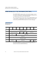
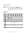
This extended message allows the target and initiator to agree on
the values of the parameters relevant to synchronous transfers. The
SuperLoader will not initiate the SYNCHRONOUS DATA
TRANSFER REQUEST message; it relies on the initiator to do so.
The SYNCHRONOUS DATA TRANSFER REQUEST message has
the format shown in figure 4.
Synchronous Data
Transfer Request
(01h)
2
Note:
The SuperLoader DLT supports initiating synchronous
transfer negotiations with the host, but this feature is
disabled by default. To enable it, set the MODE SELECT
VU EEROM parameter EnaInitSyncNeg.
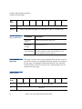
Figure 4 Synchronous
Data Transfer Request
Message
Bit
Byte
7
6
5
4
3
2
1
0
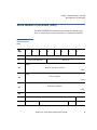
Extended Message Identifier (01h) (see figure 1)
1
Length (03h)
2
SYNCHRONOUS DATA TRANSFER REQUEST (01h)
3
Transfer Period
4
Transfer REQ/ACK Offset
0
A SYNCHRONOUS DATA TRANSFER REQUEST message
exchange is initiated by a SCSI device whenever a previously
arranged transfer width agreement may have become invalid. The
agreement becomes invalid after any condition that may leave the
data transfer agreement in an indeterminate state such as:
•
After a hard reset condition
Quantum ATL SuperLoader Software Interface Guide
21
Chapter 2 Messages
Supported SCSI Messages
•
After a BUS DEVICE RESET Message
•
After a power cycle.
•
After a WIDE DATA TRANSFER REQUEST message
exchange.
The SYNCHRONOUS DATA TRANSFER REQUEST message
exchange establishes an agreement between two SCSI devices on
the clocking of the data used for DATA phase transfer between
them. This agreement applies to DATA IN and DATA OUT phases
only. All other information transfer phases must use asynchronous
transfers.
The SuperLoader implements both wide data transfer option and
synchronous data transfer option. Wide data transfer must be
negotiated prior to negotiating the synchronous data transfer
agreement. If a synchronous data transfer agreement is in effect,
then after accepting a WIDE DATA TRANSFER REQUEST
message, it resets the synchronous agreement to asynchronous
mode.
If the Transfer Period requested is lower than the minimum value
supported by the device, the return value will be adjusted up to
the minimum supported value. All possible transfer periods
between the minimum and maximum values are not supported. If
the Transfer Period requested is between the minimum and
maximum supported values, but not exactly achievable by the
device, the returned value will be the request value and the
SuperLoader will transmit data at the next lower speed it is
capable of. The initiator may send data at the request speed. The
maximum supported synchronous period is 5Dh (372 nsec). A
request with a Transfer Period lower than this will return a request
for asynchronous mode.
22
Quantum ATL SuperLoader Software Interface Guide
Chapter 2 Messages
Supported SCSI Messages
Table 8 Transfer
Rates
Transfer
Period
Transfer Rate
0Ah
40 MHz, 25 nsec Transfer Period
0Bh
33 MHz, 30.3 nsec Transfer Period. LTO and SDLT uses 37.5 nsec period.
0Ch
20 MHz, 50 nsec Transfer Period
0Dh – 5Dh
(4 * Transfer Period) nsecs.
The minimum supported value for Transfer Period is 0Ah when
the bus is operating in LVD mode. When operating in HVD or
Single-Ended mode, the minimum Transfer Period value is 0Ch.
The SuperLoader SDLT 220 and SuperLoader SDLT 320 Transfer
REQ/ACK offset may be any value between 0 and 62. A value of 0
indicates asynchronous transfers. A request with a value greater
than 62 will cause the device to return a request for 62.
The SuperLoader DLT1 Transfer REQ/ACK offset may be any
value between 0 and 15. A value of 0 indicates asynchronous
transfers. A request with a value greater than 15 will cause the
device to return a request for 15.
The SuperLoader LTO only supports a Transfer REQA/ACK offset
of 0. This indicates asynchronous transfers.
Wide Data Transfer
Request Extended
Message (03h)
2
The following figure illustrates the message format.
Quantum ATL SuperLoader Software Interface Guide
23
Chapter 2 Messages
Supported SCSI Messages
Figure 5 Wide Data
Transfer Request
Message
Bit
Byte
7
6
5
4
3
2
1
0
Extended Message Identifier (01h) (see figure 1)
1
Extended Message Length (02h)
2
WIDE DATA TRANSFER REQUEST (03h)
3
Transfer Width Exponent
0
A WIDE DATA TRANSFER REQUEST message exchange is
initiated by a SCSI device whenever a previously arranged transfer
width agreement may have become invalid. The agreement
becomes invalid after any condition that may leave the data
transfer agreement in an indeterminate state such as
•
After a hard reset condition
•
After a BUS DEVICE RESET Message
•
After a power cycle.
The WIDE DATA TRANSFER REQUEST message exchange
establishes an agreement between two SCSI devices on the width
of the data path to be used for DATA phase transfer between them.
This agreement applies to DATA IN and DATA OUT phases only.
All other information transfer phases must use an 8-bit data path.
The SuperLoader implements both wide data transfer option and
synchronous data transfer option. It negotiates the wide data
transfer agreement prior to negotiating the synchronous data
transfer agreement. If a synchronous data transfer agreement is in
effect, then after accepting a WIDE DATA TRANSFER REQUEST
message, it resets the synchronous agreement to asynchronous
mode.
24
Quantum ATL SuperLoader Software Interface Guide
Chapter 2 Messages
Supported SCSI Messages
The transfer width is expressed as 2n where n is the transfer width
in bytes. The transfer width that is established applies to all logical
units. Valid transfer widths for the SuperLoader are 8 bits
(m = 00h) and 16 bits (m = 01h). Values of m greater than 01h are
reserved.
Quantum ATL SuperLoader Software Interface Guide
25
Chapter 2 Messages
Supported SCSI Messages
26
Quantum ATL SuperLoader Software Interface Guide
Chapter 3
3
Media Changer Commands
This chapter describes the Media Changer SCSI protocol features
implemented by the Media Changer device of the SuperLoader
system. Note that the sections included in this chapter do not fully
reiterate every ANSI SCSI option and/or command code
specification; the sections do describe the supported commands
and options.
Overview of Command and Status Processing
3
The SCSI feature set has been described as “SCSI-2 plus.” This
means the SuperLoader supports:
•
All of the mandatory features of SCSI-2
•
Many of the optional features of SCSI-2
•
Some of the mandatory and optional features of SCSI-3
Quantum ATL SuperLoader Software Interface Guide
27
Chapter 3 Media Changer Commands
Overview of Command and Status Processing
When conflicts arise between the features of SCSI-2 and SCSI-3, the
SCSI-2 methods have been chosen in all cases where execution
would differ without explicit knowledge of the host. That is, if a
command would act differently in SCSI-3 implementation without
any difference in the actual CDB, the SCSI-2 functionality is used.
If SCSI-3 defined a new functionality of a command but only with
a new field or value for a field as defined by a SCSI-3 document,
this functionality may have been implemented. Please see
individual command descriptions for the SCSI-3 features that have
been implemented.
The SuperLoader device supports the Media Changer commands
listed in table 9.
Table 9 Supported
Media Changer
Commands
Command
Operation Code
Initialize Element Status Command (07h) on page 31
07h
Inquiry Command (12h) on page 32
12h
Load Unload Command (1Bh) on page 45
1Bh
Log Sense Command (4Dh) on page 46
4Dh
Mode Select (6) / (10) Command (15h / 55h) on page 66
15h / 55h
Mode Sense (6) / (10) Command (1Ah/ 5Ah) on page 74
1Ah / 5Ah
Move Medium Command (A5h) on page 89
A5h
Persistent Reserve In Command (5Eh) on page 91 (SCSI-3)
5Eh
Persistent Reserve Out Command (5Fh) on page 101 (SCSI-3)
5Fh
Position to Element Command (2Bh) on page 116
2Bh
Prevent/Allow Medium Removal (1Eh) on page 118
1Eh
Read Buffer Command (3Ch) on page 120
3Ch
28
Quantum ATL SuperLoader Software Interface Guide
Chapter 3 Media Changer Commands
Media Changer Command Descriptions
Command
Operation Code
Read Element Status Command (B8h) on page 126
B8h
Release Element (10) Command (57h) on page 140
57h
Release Unit (6) Command (17h) on page 143
17h
Report Device Identifier Command (A3h) on page 145
A3h
Report LUNS Command (A0h) on page 148
A0h
Request Sense Command (03h) on page 151
03h
Reserve Element (10) Command (56h) on page 160 (SCSI-3)
56h
Reserve Element (6) Command (16h) on page 163
16h
Send Diagnostic Command (1Dh) on page 166
1Dh
Set Device Identifier Command (A4h) on page 168 (SCSI-3)
A4h
Test Unit Ready Command (00h) on page 170
00h
Write Buffer Command (3Bh) on page 171
3Bh
Media Changer Command Descriptions
3
The Media Changer commands are presented in alphabetical
order. Because information about a particular command may span
multiple pages, the command name is repeated, at the top of every
page that concerns that command.
Throughout this manual, multiple bytes that contain information
about specific command parameters are portrayed as shown in the
example of the Parameter List Length field (bytes 7 and 8) of the
MODE SELECT command shown as follows:
Quantum ATL SuperLoader Software Interface Guide
29
Chapter 3 Media Changer Commands
Media Changer Command Descriptions
Bit
Byte
7
6
5
4
3
2
1
0
(Bytes 0 - 6)
(MSB)
7-8
Parameter List Length
(LSB)
As shown, this sample indicates that the most significant bit (MSB)
of the field is bit 7 of byte 7; the least significant bit is bit 0 of byte 8.
30
Quantum ATL SuperLoader Software Interface Guide
Chapter 3 Media Changer Commands
Initialize Element Status Command (07h)
Initialize Element Status Command (07h)
3
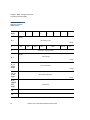
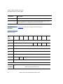
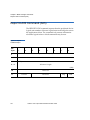
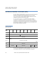
The INITIALIZE ELEMENT STATUS command allows the media
changer to check all assigned element addresses for volume and
any other status relevant to that element address. The intent of this
command is to enable the Initiator to get a quick response from a
subsequent READ ELEMENT STATUS command. It may be useful
to issue this command after a power failure, if a volume has been
changed by an operator, or if configurations have been changed.
Figure 6 Initialize
Element Status
Command
Bit
Byte
7
6
5
Logical Unit Number
2
1
0
Reserved
Reserved
2-4
5
3
Operation Code (07h)
0
1
4
Unused
Reserved
Quantum ATL SuperLoader Software Interface Guide
Flag
Link
31
Chapter 3 Media Changer Commands
Inquiry Command (12h)
Inquiry Command (12h)
3
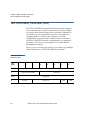
The INQUIRY command allows the initiator to determine the kind
of SCSI devices attached to its SCSI BUS. It causes a device that is
attached to a SCSI BUS to return information about itself. The
SuperLoader identifies itself as a media changer that implements
the SCSI-2 protocol.
The media changer can provide three categories of data in
response to an INQUIRY command: Standard Inquiry Data, Vital
Product Data, and Command Support Data. Standard Inquiry
Data contains basic data about the device. Vital Product Data
comprises several pages of additional data. Each Vital Product
Data page requires a separate INQUIRY command from the
initiator. Command Support Data indicates the fields in the CDB
that are supported by opcode. An INQUIRY command is not
affected by, nor does it clear, a Unit Attention condition.
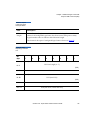
Figure 7 Inquiry
Command
Bit
Byte
7
6
5
3
Logical Unit Number
Reserved
2
Page Code
3
Reserved
4
Allocation Length
5
32
2
1
0
Operation Code (12h)
0
1
4
Unused
Reserved
Quantum ATL SuperLoader Software Interface Guide
CmdDt
EVPD
Flag
Link
Chapter 3 Media Changer Commands
Inquiry Command (12h)
Figure 8 Inquiry
Command
Field
Description
CmdDt
Command Support Data. If CmdDt = 0 and EVPD (see below) = 0, the
media changer returns the Standard Inquiry Data. If CmdDt = 1 with
EVPD = 0, the media changer returns the Command Data specified
by Page Code/ Operation. Information about Command Support
Data is provided in figure 15 on page 43 and table 14 on page 43.
EVPD
Enable Vital Product Data. If EVPD = 0 and CmdDt (see above) = 0,
the media changer returns the Standard Inquiry Data. If EVPD = 1
and CmdDt = 0, the media changer returns the Vital Product Data
Page specified by Page Code/Operation Code.
Page Code or
Operation Code
Specifies the Vital Product Data Page which is to be returned by the
media changer when EVPD is set. Specifies the SCSI Operation Code
for command support data to be returned by the media changer
when CmdDt is set. A CHECK CONDITION status is returned if this
field specifies an unsupported Page or Operation Code or if both
EVPD and CmdDt are set. Figure 11 on page 39 shows the Page
Codes for the Vital Product Pages supported by the media changer.
Allocation Length
Specifies the number of bytes of inquiry information the media
changer is allowed to return to the initiator during the command's
DATA IN phase. Error status is not returned if the value in this field
truncates the requested information.
Standard Inquiry
Data Page
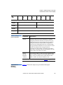
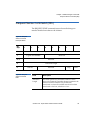
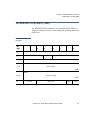
Figure 9 shows the format of the Standard Inquiry Data page
3 returned by the media changer.
Quantum ATL SuperLoader Software Interface Guide
33
Chapter 3 Media Changer Commands
Inquiry Command (12h)
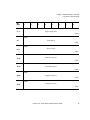
Figure 9 Standard
Inquiry Data (LTO)
Bit
Byte
7
5
4
3
Peripheral Qualifier
0
1
6
1
0
Peripheral Device Type
RMB
Reserved
Version
2
3
2
AERC
Obsolete
NormACA
HiSup
Response Data Format
Additional Length (n-4)
4
5
SCCS
Reserved
6
BQue
EncServ
Reserved
MultiP
MChngr
Obsolete
Obsolete
Add16
7
RelAdr
Obsolete
Wbus16
Sync
Linked
Obsolete
CmdQue
Reserved
8-15
Vendor Identification (QUANTUM )
16-31
Product Identification (UHDL)
32-35
Product Revision Level (hhss)
Language
36
37
38-40
41
34
Reserved
Image Type
Reserved
Firmware Personality
Quantum ATL SuperLoader Software Interface Guide
Chapter 3 Media Changer Commands
Inquiry Command (12h)
Bit
Byte
7
6
5
4
3
2
42
Firmware Subpersonality
43
Vendor-Specific Subtype
1
0
1
0
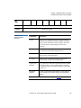
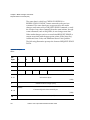
Figure 10 Standard
Inquiry Data (DLT)
Bit
Byte
7
6
2
3
4
3
Peripheral Qualifier
0
1
5
Peripheral Device Type
RMB
Device Type Modifier
ISO Version
AENC
2
TrmlOP
ECMA Version
ANSI Version
Reserved
Response Data Format
4
Additional Length (27h)
5
Reserved
6
Rsv’d
MChangr
7
RelAdr
Wbus32
Reserved
Wbus16
Sync
Linked
Rsv’d
8-15
Vendor Identification (QUANTUM)
16-31
Product Identification (UHDL)
32-35
Product Revision Level (hhss)
36-40
Reserved
Quantum ATL SuperLoader Software Interface Guide
CmdQue
SftRe
35
Chapter 3 Media Changer Commands
Inquiry Command (12h)
Bit
Byte
7
6
5
4
3
2
41
Firmware Personality
42
Firmware Subpersonality
43
Vendor-Specific Subtype
1
0
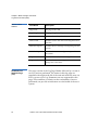
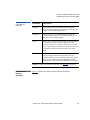
The following table contains field descriptions for the data
returned by the media changer.
Table 10 Standard
Inquiry Data (LTO and
DLT)
Field Name
Value
Description
Peripheral Qualifier
0
Non-zero if initiator selects an invalid logical unit (see below)
Peripheral Device
Type
8
8 indicates that this is a media changer device.
RMB
1
Removable Medium Bit. Set to 1.
Device Type
Modifier (DLT)
0
This vendor specific field is set to 0.
Version (LTO)
2
ANSI SCSI Level 2 (SCSI-2) is supported.
ISO Version (DLT)
0
International Standardizaation Organization Version level. Set
to 0.
ANSI Version (DLT)
2
ANSI SCSI Level 2 (SCSI-2) is supported.
AENC (DLT)
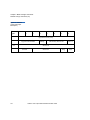
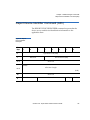
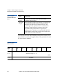
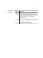
0
Asynchronous Event Notification is not supported.
AERC (LTO)
0
Asynchronous Event Notification is not supported.
36
Quantum ATL SuperLoader Software Interface Guide
Chapter 3 Media Changer Commands
Inquiry Command (12h)
Field Name
Value
Description
TrmlOP (DLT)
0
Terminate I/O Process. The media changer does not support
the TERMINATE I/O PROCESS message.
NormACA (LTO)
0
The media changer does not support the NACA bit in the
control byte of the CDB.
HiSup (LTO)
0
The hierarchical addressing model is not used.
Response Data
Format
2
This Standard Inquiry Data is in SCSI-2 format.
Additional Length
27h
This field indicates the number of additional bytes of
INQUIRY Response Data available.
SCCS (LTO)
0
This device does not contain an embedded storage array
controller.
BQue (LTO)
0
Basic queueing is not supported.
EncServ (LTO)
0
This device does not contain an embedded enclosure services
component.
MultiP (LTO)
0
This device does not implement multi-port requirements.
MChangr (LTO)
0
This device is not an attached media changer.
MChnger (DLT)
0
Set to 1 if a Media changer (loader) is present and EEPROM
parameter EnblngMedChgr is set to 1. this SCSI-3 bit indicates
that the Read Element Status and Move Medium commands
can be issued to the drive (LON0). By default, this bit is set to
0.
Add16 (LTO)
1
This devices supports 16-bit wide SCSI addresses.
RelAdr
0
This device does not support relative addressing.
WBUS32 (DLT)
0
Set to 0 since the media changer does not support 32-bit
transfer.
WBUS16
1
This device supports 16-bit wide data transfers.
Sync
0
This devices does not support synchronous data transfers.
Quantum ATL SuperLoader Software Interface Guide
37
Chapter 3 Media Changer Commands
Inquiry Command (12h)
Field Name
Value
Description
Linked
1
This device supports linked commands.
CmdQue
0
This device does not support command queueing.
SftRe
0
The hard reset option is implemented in response to assertion
of the SCSI BUS reset line.
Vendor
Identification
(QUANTUM)
Identification of vendor.
Product
Identification
(UHDL)
Identification of the product
Product Revision
Level (hhss)
This field contains 4 bytes of ASCII data that provides the
media changer’s firmware revision level.
Language (LTO)
This field indicates the language used for the front panel and
On-board Remote Web Management.
Image Type
This field indicates the type of firmware image required when
downloading a new image. SuperLoader LTO reports a 1 and
SuperLoader DLT reports a 0.
Firmware
Personality
Numeric indicator of firmware personality. Note that when
set to 4, this indicates OEM family.
Firmware
Subpersonality
Set to 1, indicating standard SCSI device firmware.
Vendor-Specific
Subtype
Identification of product.
Vital Product Data
Page
3
38
The following sections describe the Vital Product Data Pages for
the system.
Quantum ATL SuperLoader Software Interface Guide
Chapter 3 Media Changer Commands
Inquiry Command (12h)
3
Supported Vital Product Data Page
The Supported Vital Product Data Pages page provides a directory
of the Vital Product Data Pages that are supported by the
SuperLoader.
Figure 11 Supported
Vital Product Data
Bit
Byte
7
6
5
4
3
Peripheral Qualifier
0
2
1
0
Peripheral Device Type
1
Page Code (00h)
2
Reserved
3
Page Length (03h)
4
00h - (this page)
5
80h - Unit Serial Number Page
6
83h – Device Identification Page
Figure 12 Unit Serial
Number Page (80h)
Bit
Byte
0
1
7
6
5
Peripheral Qualifier
4
3
2
1
0
Peripheral Device Type
Page Code (80h)
Quantum ATL SuperLoader Software Interface Guide
39
Chapter 3 Media Changer Commands
Inquiry Command (12h)
Bit
Byte
7
6
5
4
3
2
2
Reserved
3
Page Length (0Eh)
1
0
Serial Number
4 - 17
Table 11 Unit Serial
Number Page Field
Descriptions
Field Name
Description
Serial
Number
The serial number given is the serial number of the
media changer typically starting with “PM”
indicating the site of manufacture.
Figure 13 Device
Identification Page
(83h)
Bit
Byte
0
7
6
5
Peripheral Qualifier
4
3
2
Peripheral Device Type
1
Page Code (83h)
2
Reserved
3
Page Length
4-n
40
1
Identification Descriptors
Quantum ATL SuperLoader Software Interface Guide
0
Chapter 3 Media Changer Commands
Inquiry Command (12h)
There are three different Identification Descriptors returned, in
numerical order of the Identifier Type. Each Identification
Descriptor takes the following form:
Figure 14 Identifier
Descriptor
Bit
Byte
7
6
5
3
2
1
Reserved
0
1
4
Reserved
Code Set
Association
Identifier Type
2
Reserved
3
Identifier Length (n-3)
Identifier
4-n
Table 12 Identifier
Descriptor Field
Descriptions
0
Field Name
Field Description
Code Set
Indicates the type of data to be found in the
Identifier field. A value of 1 indicates binary data. A
value of 2 indicates ASCII data.
Association
Indicates whether the Identifier is associated with
the logical unit or the port. Always contains a 0,
indicating the Identifier is associated with the
logical unit.
Identifier Type
Type of identifier.
Quantum ATL SuperLoader Software Interface Guide
41
Chapter 3 Media Changer Commands
Inquiry Command (12h)
Field Name
Field Description
Identifier
Value
Description
1
Concatenation of the Vendor Name,
Product ID, and unit serial number
2
Canonical form of the IEEE Extended
Unique Identifier, 64 bit (EIU-64)
3
FC-PH Name_Identifier
Identifier data, based on the Identifier Type.
The following table describes the identifiers supported by the
SuperLoader.
Table 13 Supported
Identifiers
Command Support
Data
3
Identifier
Type
Code
Set
Length
Identifier
1
2
24
QUANTUM UHDL, 12 ASCII space
characters (20h), followed by the unit
serial number in ASCII.
2
1
8
8 bytes of binary data indicating the
EUI-64 assigned to the drive.
3
1
8
8 bytes of binary data indicating the
64-bit, type 3, FC-PH Name_Identifer
assigned to the drive.
An application client can request command support data by
setting the CmdDt bit of the INQUIRY command to 1, and
specifying the SCSI operation code of the Command Descriptor
Block (CDB) for which it wants information.
The format of the command support data and definitions of the
fields follow.
42
Quantum ATL SuperLoader Software Interface Guide
Chapter 3 Media Changer Commands
Inquiry Command (12h)
Figure 15 Command
Support Data Page
Bit
Byte
7
0
6
5
3
Peripheral Qualifier
2
1
ISO Version
0
Peripheral Device Type
Reserved
1
2
4
Support
ECMA Version
ANSI - Approved Version
Reserved
3-4
5
CDB Size (m - 5)
6-n
CDB Usage Data
Table 14 Command
Support Data Page
Field Name
Description
Support
The value of the Support field describes the type of support that the
tape drive provides for Command Support Data.
Value
Description
000b
Data about the requested SCSI operation code is not
currently available. In this case, all data after Byte 1 is
undefined.
001b
The device does not support the SCSI operation code
requested. In this case, all data after Byte 1 is undefined.
010b
Reserved
011b
The device supports the SCSI operation code in
conformance with the SCSI standard.
Quantum ATL SuperLoader Software Interface Guide
43
Chapter 3 Media Changer Commands
Inquiry Command (12h)
Field Name
Description
100b
Vendor-Specific
101b
The device supports the SCSI operation code, but in a
vendor-specific manner.
110b
Vendor-Specific
111b
Reserved
ISO-Version
Must be 0.
ECMA-Version
Must be 0.
ANSI-Approved
Version
2.
CDB Size
This field contains the number of bytes in the CDB for the Operation
Code being requested and the size of the CDB Usage Data in the data
that is returned in response to the INQUIRY.
CDB Usage Data
This field contains information about the CDB for the Operation
Code being queried. Note that the first byte of the CDB Usage Data
contains the OpCode for the operation specified. All of the other
bytes of the CDB Usage Data contain a map for bits in the CDB of the
OpCode specified.
NOTE: The bits in the map have a 1-to-1 correspondence to the CDB for the OpCode being
queried. That is, if the device senses a bit as the entire field or as part of the field of the
operation, the map in CDB Usage Data contains a 1 in the corresponding bit position. If the
device ignores a bit or declares a bit as “reserved” in the CDB for the OpCode being queried,
the map has a 0 in that corresponding bit position.
44
Quantum ATL SuperLoader Software Interface Guide
Chapter 3 Media Changer Commands
Load Unload Command (1Bh)
Load Unload Command (1Bh)
3
The LOAD UNLOAD command tells the target to eject all
magazines. If no magazines are present, UNLOAD returns a
CHECK CONDITION status with an ILLEGAL REQUEST sense
key.
This command will eject the magazine(s) regardless of the setting
via the PREVENT/ALLOW MEDIUM REMOVAL command.
Figure 16 Load
Unload Command
Descriptor Block
Bit
Byte
7
6
5
Logical Unit Number
2
1
0
Reserved
Immed
Reserved
2-4
5
3
Operation Code (1Bh)
0
1
4
Unused
Table 15 Unload
Command Descriptor
Block
Reserved
Flag
Link
Field Name
Description
Immed
Immediate. If this bit is set to 1, status is returned as
soon as the operation is started. If set to 0, status is
returned after the operation has completed.
Quantum ATL SuperLoader Software Interface Guide
45
Chapter 3 Media Changer Commands
Log Sense Command (4Dh)
Log Sense Command (4Dh)
3
The LOG SENSE command allows the host to retrieve statistical
information maintained by the media changer about its own
hardware parameters.
Figure 17 LOG
SENSE Command
Descriptor Block
Bit
Byte
7
6
5
3
2
1
0
Operation Code (4Dh)
0
1
4
Logical Unit Number
Reserved
PC
2
PPC (0)
SP(0)
Page Code
Reserved
3-4
(MSB)
Parameter Pointer
5-6
(LSB)
(MSB)
Allocation Length
7-8
(LSB)
9
46
Unused
Reserved
Quantum ATL SuperLoader Software Interface Guide
Flag
Link
Chapter 3 Media Changer Commands
Log Sense Command (4Dh)
Table 16 Log Sense
Command Descriptor
Block
Field Name
Description
PPC
Parameter Pointer Control. A PPC of 0 indicates that the parameter data
requested from the device starts with the parameter code specified in the
Parameter Pointer field (Bytes 5 - 6) and returns the number of bytes specified
in the Allocation Length field (Bytes 7 - 8) in ascending order of parameter
codes from the specified log page. Request for changed parameters is not
supported. This field must be 0.
SP
Save Parameters. Not supported, must be set to 0. If for some reason the Save
Parameters bit is set, the command terminates with a CHECK CONDITION
status with a sense key of ILLEGAL REQUEST and an ASC of INVALID FIELD
IN CDB.
PC
Page Control. This field defines the type of parameter values to be returned:
PC
Type of Parameter Values
00b
Threshold Values
01b
Cumulative Values
10b
Default Threshold Values
11b
Default Cumulative Values
The Default Threshold Values are the maximum values that each parameter
can attain.
The Current Cumulative Values are the values computed since the last reset of
the device (either via power-cycle, BUS DEVICE RESET, or SCSI RESET.)
The Default Cumulative Values are the values to which each parameter is
initialized at a reset condition. Default values are zero.
By default, Current Threshold Values = Default Threshold Values.
Page Code
The Page Code field identifies which log page is being requested by the
initiator. If the page is not supported, then the command terminates with a
CHECK CONDITION status, sense key set to ILLEGAL REQUEST, and
additional sense code of INVALID FIELD IN CDB. Supported pages are:
Quantum ATL SuperLoader Software Interface Guide
47
Chapter 3 Media Changer Commands
Log Sense Command (4Dh)
Field Name
Parameter
Pointer
Description
Page Code
Page Definition
00h
Supported Pages Log Page (Page 00h) on page 49
07h
Last n Error Events Page (07h) on page 50
2Eh
TapeAlert Page (2Eh) on page 52 (LTO only)
30h
Move Statistics Page (30h) on page 54
31h
Hard/Soft Error Statistics Page (31h) on page 56
33h
Device Wellness Page (33h) on page 59
3Eh
Device Status Page (3Eh) on page 62
SDLT and DLT must be 0.
For LTO only: The Parameter Pointer field allows the host to specify at which
parameter within a log page the requested data should begin. For example, if a
page supports parameters 0 through 5, and the Parameter Pointer contains 3,
then only parameters 3, 4, and 5 are returned to the initiator. Similarly, if a page
supports parameters 1, 3, and 6, and the Parameter Pointer contains 2, then
only parameters 3 and 6 are returned to the initiator.
If the Parameter Pointer is larger than the highest numbered parameter on the
page, then the target terminates the command with CHECK CONDITION
status, sense key set to ILLEGAL REQUEST, and additional sense code set to
INVALID FIELD IN CDB.
Note that parameters within a page are always returned in ascending order
according to parameter code.
If the target does not support a parameter code within this page, then it does
not return any data associated with this parameter.
Allocation
Length
48
This field specifies the maximum number of bytes that the initiator has
allocated for returning data. The host uses this field to limit the size of data
transfers to its own internal buffer size.
Quantum ATL SuperLoader Software Interface Guide
Chapter 3 Media Changer Commands
Log Sense Command (4Dh)
When page 00h is requested, the 4-byte page header is returned,
followed by the pages supported in ascending order, one byte for
each.
Supported Pages
Log Page (Page
00h)
3
Figure 18 Supported
Pages Page
Bit
Byte
0
7
6
5
4
3
Reserved
2
1
0
Page Code (00h)
Reserved
1
(MSB)
2–3
Page Length (7h)
(LSB)
4
00h
5
07h
6
2Eh
7
30h
8
31h
9
33h
10
3Eh
Quantum ATL SuperLoader Software Interface Guide
49
Chapter 3 Media Changer Commands
Log Sense Command (4Dh)
This page returns the ASCII text for the hard error event log. This
page consists of a page header, a parameter header and parameter
value. The parameter value returned consists of the ASCII text for
the EEROM Hard Error Log.
Last n Error Events
Page (07h)
3
Figure 19 Last n Error
Events Log Sense
Header
Bit
Byte
0
7
6
5
4
3
Reserved
2
1
0
Page Code (07h)
Reserved
1
(MSB)
Page Length (n)
2-3
(LSB)
Table 17 Last n Error
Events Log Sense
Header
50
Field Name
Description
Page Code
The Page Code echoes the page code that was
specified in the LOG SENSE command descriptor
block.
Page Length
The Page Length field specifies the total number of
bytes contained in this log page, not including the
four bytes that make up the header.
Quantum ATL SuperLoader Software Interface Guide
Chapter 3 Media Changer Commands
Log Sense Command (4Dh)
Figure 20 Format for
Last n Error Events
Log Sense
Bit
Byte
7
6
5
4
3
2
1
0
(MSB)
Parameter Code
0 -1
(LSB)
2
DU
DS
TSD
ETC
TMC
Rsv’d
LP
Parameter Length
3
(MSB)
ASCII String for Event n
4-n
(LSB)
Table 18 Parameters
Last n Error Events
Log Sense
Field Name
Description
Parameter Code
The Parameter Code value represents the relative
time at which the error occurred. It identifies the
log parameter being transferred for that log page.
Only the most recent 10 events are reported in the
SuperLoader LTO and 5 events for the
SuperLoader DLT..
DU
Disable Update. Not supported, always 0.
DS
Disable Save. Not supported, always 1.
TSD
Target Save Disable. Not supported, always 1.
ETC
Enable Threshold Comparison. Not supported,
always 0.
TMC
Threshold Met Criteria. Not supported, always 0.
Quantum ATL SuperLoader Software Interface Guide
51
Chapter 3 Media Changer Commands
Log Sense Command (4Dh)
TapeAlert Page
(2Eh)
Field Name
Description
LP
List Parameter. This bit is set to 1.
Parameter
Length
The length in bytes of the following parameter
value.
ASCII Strong for
Event n
The text includes the time of the event, the error
code indentifying the event, and additional data
specific to the event.
The TapeAlert Log page defines error and informational flags for
3 detailed device diagnostics. The TapeAlert data is event-based and
the page control bits in the LOG SENSE command are not
applicable and are ignored.
The SuperLoader LTO supports the definition of the flags for
media changer devices as defined in SMC-2.
The SuperLoader DLT only supports the reporting of the
TapeAlert Log page on logical unit 0. It supports the combined
drive and media changer flags are defined in SSC-2.
Figure 21 TapeAlert
Log Sense Header
Format
Bit
Byte
0
52
7
6
5
4
3
2
Page Code (2Eh)
Quantum ATL SuperLoader Software Interface Guide
1
0
Chapter 3 Media Changer Commands
Log Sense Command (4Dh)
Bit
Byte
7
6
5
4
3
2
1
0
Reserved
1
(MSB)
Page Length
2-3
(LSB)
Table 19 TapeAlert
Log Sense Header
Field Descriptions
Field Name
Description
Page Code
The Page Code echoes the page code that was
specified in the LOG SENSE command descriptor
block.
Page Length
The Page Length field specifies the total number of
bytes contained in this log page, not including the
four bytes that make up the header.
Figure 22 TapeAlert
Page Log Parameters
Format
Bit
Byte
5n – 1
to
5n
5n + 1
7
6
5
4
3
2
1
0
MSB
Parameter Code (n)
(LSB)
DU
DS
TSD
ETC
TMC
Quantum ATL SuperLoader Software Interface Guide
Rsv’d
LP
53
Chapter 3 Media Changer Commands
Log Sense Command (4Dh)
Bit
Byte
7
6
5
4
3
2
1
0
5n + 2
Parameter Length
5n + 3
Value of TapeAlert Flag (Flag is set when Bit 0 = 1; Bits 1 - 7 are Reserved)
Table 20 TapeAlert
Page Log Parameters
Move Statistics
Page (30h)
Field Name
Description
Parameter
Code
This field contains the Flag code.
Parameter
Length
This field is set to 1.
Value of
TapeAlert Flag
If Bit 0 is set to 1, indicates that TapeAlert has
sensed a problem. If Bit 0 is 0, the Flag is not set
and no problem has been sensed.
This page consists of the Log Page Header followed by a count of
3 various movements of cartridges within the system. The entries in
the log page are cumulative throughout the life of the unit and
cannot be reset via SCSI or power cycle. Log Parameters are not
supported for this page.
Figure 23 Move
Statistics Format
Bit
Byte
0
1
54
7
6
5
Reserved
4
3
2
Page Code (30h)
Reserved
Quantum ATL SuperLoader Software Interface Guide
1
0
Chapter 3 Media Changer Commands
Log Sense Command (4Dh)
Bit
Byte
7
6
5
4
3
2
1
0
(MSB)
Page Length (18h)
2-3
(LSB)
(MSB)
Total Moves
4-7
(LSB)
(MSB)
Drive Loads
8-11
(LSB)
(MSB)
Mail Slot Imports
12-15
(LSB)
(MSB)
Mail Slot Exports
16-19
(LSB)
(MSB)
Magazine Moves
20-23
(LSB)
(MSB)
24-27
Magazine Loads
(LSB)
Quantum ATL SuperLoader Software Interface Guide
55
Chapter 3 Media Changer Commands
Log Sense Command (4Dh)
Table 21 Move
Statistics
Hard/Soft Error
Statistics Page
(31h)
56
3
Field Name
Description
Page Code
The page code is 30h.
Page Length
The page length is 18h bytes.
Total Moves
Total number of SuperLoader moves.
Drive Loads
Number loads to the drive from magazines and
mail slot.
Mail Slot Imports
Number times a cartridge was importing into the
system.
Mail Slot Exports
Number of times a cartridge was exported from
the system.
Magazine Moves
Number of moves between storage slots.
Magazine Loads
Number of times a cartridge was moved from a
storage slot to the drive.
This page consists of the Log Page Header followed by a count of
recovery actions performed. The entries in this log page are
cumulative throughout the life of the unit and cannot be reset via
SCSI or power cycle. Log Parameters are not supported for this
page. These numbers, in relation to the total number of moves
performed, can provide an indication as to the health of the servo
system.
Quantum ATL SuperLoader Software Interface Guide
Chapter 3 Media Changer Commands
Log Sense Command (4Dh)
Figure 24 Hard/Soft
Move Error Statistics
Format
Bit
Byte
0
7
6
5
Reserved
4
3
2
1
0
Page Code (31h)
Reserved
1
(MSB)
Page Length (22h)
2-3
(LSB)
(MSB)
Servo Hard Errors
4-5
(LSB)
(MSB)
Drive Soft Error
6-9
(LSB)
(MSB)
Left Magazine Soft Error
10-13
(LSB)
(MSB)
Right Magazine Soft Error
14-17
(LSB)
(MSB)
18-21
Mail Slot Soft Error
(LSB)
Quantum ATL SuperLoader Software Interface Guide
57
Chapter 3 Media Changer Commands
Log Sense Command (4Dh)
Bit
Byte
7
6
5
4
3
2
1
0
(MSB)
Rotation Recovery Actions
22-25
(LSB)
(MSB)
Translation Recovery Actions
26-29
(LSB)
(MSB)
Left Magazine Recovery Actions
30-33
(LSB)
(MSB)
Right Magazine Recovery Actions
34-37
(LSB)
Table 22 Hard/Soft
Error
58
Field Name
Description
Page Code
The page code is 31h.
Page Length
The page length is 22h bytes.
Servo Hard Errors
The number of unrecoverable errors.
Soft Errors
Each field is a count of the number of times
high-level recoverable error was reported for
that component.
Recovery Actions
Each field is a count of the number of times
recovery actions were required in that axis to
perform an operation.
Quantum ATL SuperLoader Software Interface Guide
Chapter 3 Media Changer Commands
Log Sense Command (4Dh)
Device Wellness
Page (33h)
The Device Wellness Page returns information about any check
3 conditions related to Sense Keys 4 and 9 logged by the media
changer. Up to 16 entries (parameter code 0000h to 000Fh) can be
contained in the page. Each entry records a hardware error (Sense
Key = 4) or a code update event (Sense Key = 9). Note that
parameter code 000h contains the oldest log information while
parameter 000Fh contains the most recent.
This page begins with a 4-byte header followed by the log
parameter blocks.
Figure 25 Device
Wellness Log Sense
Header
Bit
Byte
0
7
6
5
4
3
Reserved
2
1
0
Page Code (33h)
Reserved
1
(MSB)
Page Length
2-3
(LSB)
Table 23 Device
Wellness Log Sense
Header
Field Name
Description
Page Code
The Page Code echoes the page code that was
specified in the LOG SENSE command descriptor
block.
Page Length
The Page Length field specifies the number of bytes
available and depends on the parameters requested.
Quantum ATL SuperLoader Software Interface Guide
59
Chapter 3 Media Changer Commands
Log Sense Command (4Dh)
Figure 26 Device
Wellness Log Sense
(0000h-000Fh)
Bit
Byte
7
6
5
4
3
2
1
0
(MSB)
Parameter Code
0-1
(LSB)
2
DU
DS
TSD
ETC
TMC
Rsv’d
LP
Parameter Length (0Ch)
3
(MSB)
Time Stamp
4-7
(LSB)
8-9
(LTO
only)
10 - 11
(LTO
only)
(MSB)
Source Element
(LSB)
(MSB)
Destination Element
(LSB)
8-11
(SDLT/
DLT
only)
Media ID
12
Sense Key
13
Additional Sense Code
60
Quantum ATL SuperLoader Software Interface Guide
Chapter 3 Media Changer Commands
Log Sense Command (4Dh)
Bit
Byte
7
6
5
4
3
2
14
Additional Sense Code Qualifier
15
Additional Error Information
1
0
Figure 27 Log
Parameters for Device
Wellness Log Sense
Field Name
Description
Parameter
Code
Parameter Codes 0000h through 000Fh are supported. This provides 16 log
entries for error information capture.
DU
Disable Update. Always 0.
DS
Disable Save. Not supported. This bit always set to 1.
TSD
Target Save Disable. Not supported. This bit always set to 1.
ETC
Enable Threshold Comparison. Threshold checking is not supported on this
page. Always set to 0.
TMC
Threshold Met Criteria. Always 0.
LP
List Parameter. Always set to 0.
Parameter
Length
The number of bytes to follow (0Ch).
Time Stamp
LTO: The Time Stamp is represented as number of power cycles and total
power on hours.
SDLT/DLT: Tape motion hours when check condition occurred (note that
this is the number of power-on hours since the last time the unit was
powered on, not total number of hours during the lifetime of the drive).
The time stamp counter is updated once per hour; if the tape drive is
powered down before the hourly update occurs, the update will not occur
until a full hour after power is reapplied.
Quantum ATL SuperLoader Software Interface Guide
61
Chapter 3 Media Changer Commands
Log Sense Command (4Dh)
Field Name
Description
Media ID
SDLT/DLT only: Internal media identifier being used when check condition
occurred. 0 = no media or unknown media when event occurred. Note that
this is not an applicable means of tracing media.
Source
Element/
Destination
Element
LTO only: These fields report the element addresses that were involved in the
failure. These fields will be zero (0) if the failure did not involve a move
command.
The Device Status Page describes the current status of the media
changer.
Device Status Page
(3Eh)
3
Figure 28 Device
Status Log Sense
Header
Bit
Byte
0
7
6
5
Reserved
4
3
2
1
0
Page Code (3Eh)
Reserved
1
(MSB)
2-3
Page Length
(LSB)
62
Quantum ATL SuperLoader Software Interface Guide
Chapter 3 Media Changer Commands
Log Sense Command (4Dh)
Table 24 Device
Status Log Sense
Header
Field Name
Description
Page Code
The Page Code echoes the page code that was
specified in the LOG SENSE command descriptor
block.
Page Length
The Page Length field specifies the number of bytes
available and depends on the parameters requested.
Figure 29 Parameters
for Device Status Log
Sense Page
Bit
Byte
7
6
5
4
3
2
1
0
Parameter Code
0-1
DU
2
DS
TSD
ETC
TMC
Rsv’d
LP
Parameter Length (04h)
3
(MSB)
Parameter Value
4-7
(LSB)
Table 25 Parameters
for Device Status Log
Sense Page
Field Name
Description
Parameter Code
Parameter Codes 0000h through 0004h are supported:
Code
Description
Quantum ATL SuperLoader Software Interface Guide
63
Chapter 3 Media Changer Commands
Log Sense Command (4Dh)
Field Name
Description
0000h
Specifies device type. This value is always 0h.
0001h
Specifies device status (figure 30).
0002h
Specifies the number of move operations over the lifetime of the device.
0003h
Reserved for media changer device and shall contain 0.
0004h
Vendor specific
DU
Disable Update. Always 0.
DS
Disable Save. Not supported. This bit always set to 1.
TSD
Target Save Disable. Not supported. This bit always set to 1.
ETC
Enable Threshold Comparison. Threshold checking is not supported on
this page. Always set to 0.
TMC
Threshold Met Criteria. Always 0.
LP
List Parameter. Always set to 0 (parameter codes treated as data
counter).
Figure 30 Device
Status Log Sense
Page (0001h)
Bit
Byte
7
6
5
2-3
64
3
2
1
0
Reserved
0
1
4
Reserved
Temperature
Reserved
Quantum ATL SuperLoader Software Interface Guide
Status
Chapter 3 Media Changer Commands
Log Sense Command (4Dh)
Table 26 Device
Status Log Sense
(0001h)
Field Name
Description
Temperature
These two bits indicate the temperature of the device. This field follows the
following format:
Status
Bit 3
Bit 2
Description
0
0
Not supported
0
1
OK
1
0
Warning: Safe temperature exceeded.
1
1
Maximum temperature exceeded.
These two bits indicate the overall condition of the device. The status of the
device follows the following format:
Bit 1
Bit 0
Description
0
0
Not supported
0
1
OK
1
0
Degraded
1
1
Failed
Quantum ATL SuperLoader Software Interface Guide
65
Chapter 3 Media Changer Commands
Mode Select (6) / (10) Command (15h / 55h)
Mode Select (6) / (10) Command (15h / 55h)
3
The MODE SELECT command (available in either 6- or 10-byte
format) enables the host to configure the media changer.
Implementing MODE SELECT and MODE SENSE requires
“handshaking” between the host and the media changer. Before
configuring the media changer, the host should issue a MODE
SENSE command to the media changer to obtain a report of the
current configuration and determine what parameters are
configurable. The host interprets this information and then may
issue MODE SELECT to set the media changer to the host’s
preferred configuration. The Mode Parameter List described in
Mode Parameter List on page 68 is passed from the initiator to the
media changer during the command’s DATA OUT phase. The
media changer device does not allow the host to save any values
on any page.
Information for the media changer is carried on a number of pages,
each of which serves to set the media changer’s operating
parameters. The MODE SELECT pages supported, and the page
within this manual that details each, are:
66
Page Code
Description
1Ch
TapeAlert Page (1Ch) on page 79 (LTO only)
1Dh
Element Address Assignment Page on page 82
1Eh
Transport Geometry Parameters Page on page 85
1Fh
Device Capabilities Page on page 86
Quantum ATL SuperLoader Software Interface Guide
Chapter 3 Media Changer Commands
Mode Select (6) / (10) Command (15h / 55h)
Figure 31 Mode
Select (6) Command
Descriptor
Bit
Byte
7
6
5
4
3
2
1
0
Operation Code (15h)
0
Logical Unit Number
1
PF
Reserved
SP (0)
Reserved
2–3
Parameter List Length
4
Unused (00)
5
Reserved
Flag
Link
Figure 32 Mode
Select (10) Command
Descriptor
Bit
Byte
7
6
5
3
Logical Unit Number
PF
2–6
Reserved
7-8
Parameter List Length
9
2
1
0
Operation Code (55h)
0
1
4
Unused (00)
Reserved
Reserved
Quantum ATL SuperLoader Software Interface Guide
SP (0)
Flag
Link
67
Chapter 3 Media Changer Commands
Mode Select (6) / (10) Command (15h / 55h)
Table 27 Mode
Select (6)/(10)
Command Descriptor
Mode Parameter
List
Field Name
Description
PF
Page Format. The Page Format bit indicates that the
data sent by the host after the MODE SELECT header
and block descriptors complies with the definition of
pages in the SCSI-2 specification. The SCSI-1 format
will not be implemented so this bit must be set to 1. It
is an ILLEGAL REQUEST to have page parameters
while the PF bit is 0.
SP
Save Parameters. Must be 0. If set, this bit instructs the
SuperLoader to save all savable pages, and this is not
supported.
The following figure shows the format of the Mode Parameter List
3 that is passed by the initiator to the media changer during the
command’s DATA OUT phase.
Figure 33 Mode
Select (6) Mode
Parameter List
Bit
Byte
7
6
5
4
3
2
0-3
Mode Parameter Header
4 - 11
Mode Parameter Block Descriptor (Optional)
4 – 11 or
12 - n
68
Page(s) (Optional)
Quantum ATL SuperLoader Software Interface Guide
1
0
Chapter 3 Media Changer Commands
Mode Select (6) / (10) Command (15h / 55h)
Figure 34 Mode
Select (10) Mode
Parameter List
Bit
Byte
7
6
5
4
3
2
0-7
Mode Parameter Header
8 - 15
Mode Parameter Block Descriptor (Optional)
0
Page(s) (Optional)
8-n
or 16 - n
Table 28 Mode
Select Parameter List
1
Field Name
Description
Mode Parameter
Header
4 or 8 bytes in length, contains information about
the remainder of the Parameter List and is always
present.
Mode Parameter
Block Descriptor
8 bytes in length; not applicable to a media
changer device.
Page(s)
The Page Code(s) of the pages that are a part of
this MODE SELECT command.
Mode Parameter Header
3
The figures and table that follow provide an illustration and
description of the fields that make up the MODE SELECT
command’s Mode Parameter header.
Quantum ATL SuperLoader Software Interface Guide
69
Chapter 3 Media Changer Commands
Mode Select (6) / (10) Command (15h / 55h)
Figure 35 Mode
Select (6) Parameter
Header
Bit
Byte
7
6
5
4
3
2
1
0
2
1
0
0
Reserved
1
Reserved
2
Reserved
3
Block Descriptor Length
Figure 36 Mode
Select (10) Parameter
Header
Bit
Byte
7
6
5
4
3
0-1
Reserved
2
Reserved
3
Reserved
4-5
Reserved
6-7
Block Descriptor Length
70
Quantum ATL SuperLoader Software Interface Guide
Chapter 3 Media Changer Commands
Mode Select (6) / (10) Command (15h / 55h)
Table 29 Mode
Select Parameter
Header
Field Name
Description
Block
Descriptor
Length
This field specifies the length in bytes of all the block
descriptors. Since the media changer only allows one
block descriptor, the value must be either 0 or 8. A
value of 0 indicates no block description is included;
a value of 8 indicates a block descriptor is present and
precedes the mode page data. Any other value other
than 0 or 8 causes a CHECK CONDITION status with
sense key of ILLEGAL REQUEST to be returned.
3
Mode Parameter Block Descriptor
The figure and table that follow provide an illustration and
description of the fields that make up the MODE SELECT
command’s Mode Parameter Block Descriptor.
Figure 37 Mode
Select Parameter
Bit
Byte
7
6
5
4
3
2
1
0
Reserved
0
(MSB)
Number of Blocks
1-3
(LSB)
Reserved
4
(MSB)
5-7
Block Length
(LSB)
Quantum ATL SuperLoader Software Interface Guide
71
Chapter 3 Media Changer Commands
Mode Select (6) / (10) Command (15h / 55h)
Table 30 Mode
Select Parameter
Block
Field Name
Description
Number of
Blocks
This field is sent as 0. It is not applicable to media
changer devices.
Block Length
This field is sent as 0. It is not applicable to media
changer devices.
3
Mode Page Descriptors
Following the MODE SELECT command’s Mode Parameter Block
Descriptor are the MODE SELECT pages, each of which sets a
different device parameter. Each mode page has a 2-byte header
that identifies the page code and indicates the number of bytes in
that page.
Figure 38 Mode
Select Page
Descriptor
Bit
Byte
0
1
2-n
72
7
PS (0)
6
5
0
4
3
2
1
Page Code
Additional Page Length
Page-Defined or Vendor Specific Parameter List
Quantum ATL SuperLoader Software Interface Guide
0
Chapter 3 Media Changer Commands
Mode Select (6) / (10) Command (15h / 55h)
Table 31 Mode
Select Page
Descriptor
Field Name
Description
PS
Parameters Savable. For the MODE SELECT (6)
(10) commands, this field is reserved (0).
Additional Page
Length
Indicates number of bytes in that page (not
including bytes 0 and 1).
Page-Defined or
Vendor Specific
Parameter List
Information in this field depends on the mode
page. Refer to Element Address Assignment Page
on page 82 to Device Capabilities Page on
page 86.
Quantum ATL SuperLoader Software Interface Guide
73
Chapter 3 Media Changer Commands
Mode Sense (6) / (10) Command (1Ah/ 5Ah)
Mode Sense (6) / (10) Command (1Ah/ 5Ah)
3
The MODE SENSE command allows the media changer to report
its current or changeable configuration parameters to the host. It is
a complementary command to MODE SELECT.
The command descriptor block for the 6-byte MODE SENSE (1Ah)
is shown below. An illustration of the command descriptor block
for the 10-byte MODE SENSE (5Ah) follows on the next page.
Figure 39 Mode
Sense (6) Command
Descriptor Block
Bit
Byte
7
6
5
2
3
2
Logical Unit Number
Rsv’d
DBD
PC
0
Reserved
Page Code
3
Reserved
4
Allocation Length
5
1
Operation Code (1Ah)
0
1
4
Unused
Reserved
Flag
Link
The MODE SENSE (10) command returns descriptor data in a
different format than MODE SENSE (6).
74
Quantum ATL SuperLoader Software Interface Guide
Chapter 3 Media Changer Commands
Mode Sense (6) / (10) Command (1Ah/ 5Ah)
Figure 40 Mode
Sense (10) Command
Descriptor Block
Bit
Byte
7
6
5
4
3
2
1
0
Operation Code (5Ah)
0
Logical Unit Number
1
Rsv’d
DBD
PC
2
Reserved
Page Code
Reserved
3–6
(MSB)
Allocation Length
7-8
(LSB)
9
Unused
Reserved
Flag
Link
Table 32 Mode
Sense Command
Descriptor Block
Field Name
Description
DBD
Disable Block Descriptors. This field is ignored. This device does not return
a block descriptor regardless of this field.
PC
Page Control. The Page Control field indicates the type of page parameter
values to be returned to the host:
PC
Type of Parameter Values
00
Report Current Values
01
Report Changeable Values
Quantum ATL SuperLoader Software Interface Guide
75
Chapter 3 Media Changer Commands
Mode Sense (6) / (10) Command (1Ah/ 5Ah)
Field Name
Description
10
Report Default Values
11
Report Saved Values
Note that the media changer device does not support saved values.
Page Code
Allocation
Length
This field allows the host to select any specific page or all of the pages
supported by the media changer.
Page Code
Description
1Ch
TapeAlert Page (1Ch) on page 79 (LTO only)
1Dh
Element Address Assignment Page on page 82
1Eh
Transport Geometry Parameters Page on page 85
1Fh
Device Capabilities Page on page 86
3Fh
Return all pages
This field specifies the number of bytes that the host has allocated for
returned MODE SENSE data. An allocation length of zero indicates that the
media changer will return no MODE SENSE data. This is not considered an
error, and GOOD status is returned.
MODE SENSE may be either MODE SENSE (6) or MODE SENSE
(10). MODE SENSE (6) data contains a 4-byte header followed by
one 8-byte block descriptor, followed by zero or more variable
length pages, depending on the Page Code and Allocation Length.
Mode Sense Data
Headers
3
76
The MODE SENSE (6) and MODE SENSE (10) headers are
illustrated in the following figures.
Quantum ATL SuperLoader Software Interface Guide
Chapter 3 Media Changer Commands
Mode Sense (6) / (10) Command (1Ah/ 5Ah)
Figure 41 Mode
Sense (6) Data
Header
Bit
Byte
7
6
5
4
3
2
0
Mode Sense Data Length
1
Reserved
2
Reserved
3
Block Descriptor Length (0)
1
0
1
0
Figure 42 Mode
Sense (10) Data
Header
Bit
Byte
7
6
5
4
3
2
(MSB)
Mode Sense Data Length
0-1
(LSB)
2
Reserved
3
Reserved
4-5
Reserved
(MSB)
6-7
Block Descriptor Length (0)
(LSB)
Quantum ATL SuperLoader Software Interface Guide
77
Chapter 3 Media Changer Commands
Mode Sense (6) / (10) Command (1Ah/ 5Ah)
Table 33 Mode
Sense Data Heade
Field Name
Description
Mode Sense
Data Length
This field specifies the length (in bytes) of the MODE
SENSE data that is available to be transferred during
the DATA IN phase. Note that the Mode Sense Data
Length does not include itself.
Block
Descriptor
Length
This field specifies the length (in bytes) of all of the
block descriptors. This value will be 0, indicating no
Block Descriptors were sent.
The following figure depicts the variable length page descriptor.
Mode Sense Mode
Pages
3
Figure 43 Mode
Sense Page
Descriptor
Bit
Byte
0
7
6
PS
5
0
4
3
2
1
0
Page Code
1
Additional Page Length
2
Page Defined or Vendor Specific Parameter Bytes
Descriptions of the MODE SENSE page descriptor fields are
provided in the following table. Detailed descriptions of each of
the MODE SENSE Pages follow.
78
Quantum ATL SuperLoader Software Interface Guide
Chapter 3 Media Changer Commands
Mode Sense (6) / (10) Command (1Ah/ 5Ah)
Table 34 Mode
Sense Page
Descriptor
TapeAlert Page
(1Ch)
Field Name
Description
PS
Parameters Savable. When 0, the supported
parameters cannot be saved (savable pages are not
supported). When set to 1, it indicates that the page
can be saved in nonvolatile memory by the media
changer.
Additional Page
Length
This field indicates the number of bytes in the page.
Note that this value does not include bytes 0 and 1.
The length is returned on MODE SENSE and must
subsequently be set to the same value when
performing MODE SELECT.
LTO only: The SuperLoader supports the TapeAlert Page that is
3 used to set/change the supported TapeAlert configuration
options. Use the MODE SENSE command to read the settings of
the TapeAlert page.
Figure 44 TapeAlert
Page Format
Descriptor
Bit
Byte
0
7
6
PS (0)
5
0
3
3
2
1
0
Page Code (1Ch)
Additional Page Length (0Ah)
1
2
4
Perf
Reserved
DExcpt
Test
Reserved
Quantum ATL SuperLoader Software Interface Guide
Rsvd
LogErr
MRIE
79
Chapter 3 Media Changer Commands
Mode Sense (6) / (10) Command (1Ah/ 5Ah)
Bit
Byte
7
6
5
4
3
2
1
0
(MSB)
Interval Timer
4-7
(LSB)
MSB)
Report Count/Test Flag Number
8 - 11
(LSB)
Table 35 TapeAlert
Page Format
Descriptor
Field Name
Description
PS
Parameters Savable. Not supported, this bit must be 0.
Additional Page
Length
This field indicates the number of bytes in the page. However, this value
does not include bytes 0 and 1. The length is returned on MODE SENSE
and must subsequently be set to the same value when performing
MODE SELECT. If the page length does not match that expected by the
drive, a CHECK CONDITION status is returned, sense key set to
ILLEGAL REQUEST.
The device returns a CHECK CONDITION status with sense key set to
ILLEGAL REQUEST if it receivees an unsupported Page Code or a Page
field with values not supported or changeable. In such cases, no
parameters are changed as a result of the command.
Perf
Performance bit. Performance Impacting Exceptions are acceptable. This
bit is ignored.
DExcpt
Disable Information Exception Operations. If = 0, the reporting method
specified by the contents of MRIE is selected. When this bit is set to 1, all
information exception conditions are disabled regardless of the contents
for the MRIE field. To enable CHECK CONDITION mode, DExcpt
should = 0. Default setting = 1.
80
Quantum ATL SuperLoader Software Interface Guide
Chapter 3 Media Changer Commands
Mode Sense (6) / (10) Command (1Ah/ 5Ah)
Field Name
Description
Test
Test bit. Used to generate false TapeAlert conditions to test the response
to failure conditions. See the Report Count/Test Flag Number
description for more information. If both Test and DExcpt are set to 1, the
drive will return CHECK CONDITION status, with a send key ILLEGAL
REQUEST, and additional sense data of INVALID FIELD IN
PARAMETER LIST.
LogErr
Error Log. Not supported.
MRIE
Method for Reporting Information Exceptions. The tape drive uses the
contents of this field to report information about exception conditions.
Value
Method
00h
No reporting of Informational Exception Conditions.
The device server does not report information exception
conditions.
03h
Conditionally Generate Recovered Error. The device
server reports information exception conditions, if such
reports of recovered errors is allowed, by returning
CHECK CONDITION status on the next SCSI command
(except INQUIRY and REQUEST SENSE commands)
following detection of the condition. The Sense Key is
set to RECOVERED ERROR with an additional sense
code of 5D 00 (TapeAlert Event). The SCSI command
with CHECK CONDITION completes without error
prior to the report of any exception condition, and does
not need to be repeated.
04h
Unconditionally Generate Recoevered Error. The drive
reports information exception conditions by returning
CHECK CONDITION status on the next SCSI command
(except INQUIRY and REQUEST SENSE commands)
following detection of the condition. The Sense Key is
set to RECOVERED ERROR with an additional sense
code of 5D 00 (TapeAlert Event). The SCSI command
with CHECK CONDITION completes without error
prior to the report of any exception condition, and does
not need to be repeated.
Quantum ATL SuperLoader Software Interface Guide
81
Chapter 3 Media Changer Commands
Mode Sense (6) / (10) Command (1Ah/ 5Ah)
Field Name
Description
06h
Only Report Informational Exception Condition on
Request. The device server preserves informational
exception data. To access the data, a poll can be taken by
issuing an unsolicited REQUEST SENSE command. The
Sense Key is set to NO SENSE with an additional sense
code of 5D 00 (TapeAlert Event).
The additional sense code of 5D 00 for values 03h, 04h,
and 06h signals that a TapeAlert event has occurred.
Information about the event is stored in the TapeAlert
Log Page. The setting of MRIE does not impact logging
of events in the TapeAlert Log Page.
Interval Timer
Not supported.
Report Count/Test
Flag Number
Report Count or Test Flag Number. This field must be set to 0 unless the
Test bit is set. When the Test bit is set, this field indicates that a test
condition to be generated as follows:
Element Address
Assignment Page 3
82
Value
Result
0
Change no TapeAlert Flag but report an exception
condition based on the setting of the MRIE field.
1 to 64
Set the TapeAlert flag indicated in the value and
generate an exception condition based on the MRIE
field.
-1 to -64
Clear the TapeAlert flag in an equivalent manner to
taking corrective action of indicated by the absolute
number of the value.
32767
Set all TapeAlert flags and generate and exception
condition based on the setting of the MRIE field.
The element address assignment page is used to report element
address assignments to the host. This page also defines the number
of each type of element present. None of the fields in this page are
changeable.
Quantum ATL SuperLoader Software Interface Guide
Chapter 3 Media Changer Commands
Mode Sense (6) / (10) Command (1Ah/ 5Ah)
Figure 45 Element
Address Assignment
Page
Bit
Byte
0
7
PS (0)
6
5
RSVD
4
3
2
1
0
Page Code (1Dh)
Parameter List Length (12h)
1
(MSB)
First Medium Transport Element Address
2-3
(LSB)
(MSB)
Number of Medium Transport Elements
4-5
(LSB)
(MSB)
First Storage Element Address
6-7
(LSB)
(MSB)
Number of Storage Elements
8-9
(LSB)
(MSB)
First Import/Export Element Address
10-11
(LSB)
(MSB)
12-13
Number of Import/Export Address
(LSB)
Quantum ATL SuperLoader Software Interface Guide
83
Chapter 3 Media Changer Commands
Mode Sense (6) / (10) Command (1Ah/ 5Ah)
Bit
Byte
7
6
5
4
3
2
1
0
(MSB)
First Data Transfer Element Address
14-15
(LSB)
(MSB)
Number of Data Transfer Elements
16-17
(LSB)
Reserved
18-19
Table 36 Element
Address Assignment
Page
Field Name
Description
First Medium Transport
Element Address
Identifies the address of the first medium transport element
contained in the media changer. The SuperLoader uses the
default address of 0.
Number of Medium
Transport Elements
Defines the total number of medium transport elements
contained in the media changer. The SuperLoader contains 1.
First Storage Element
Address
Identifies the address of the first medium storage element
contained in the media changer.
Number of Storage
Elements
Defines the total number of storage elements contained in the
media changer. There are 16 total, although since the magazines
are removable, 8 of them may be “inaccessible” at times.
First Import/Export
Element Address
Identifies the address of the first import/export element that is
accessible both by the medium transport device and also by an
operator from outside the media changer.
Number of Import/Export
Elements
Defines the total number of import/export elements contained in
the media changer.
84
Quantum ATL SuperLoader Software Interface Guide
Chapter 3 Media Changer Commands
Mode Sense (6) / (10) Command (1Ah/ 5Ah)
Field Name
Description
First Data Transfer Element
Address
Identifies the address of the first data transfer element contained
in the media changer. The first element is 0020h.
Number of Data Transfer
Elements
Defines the total number of data transport elements contained in
the media changer. The SuperLoader contains 1.
The transport geometry parameters page defines whether each
medium transport element of a media changer is a member of a set
of elements that share a common robotics subsystem and whether
the element is capable of media rotation. One transport geometry
descriptor is transferred for each medium transport element,
beginning with the first medium transport element. None of the
fields in the page are changeable.
Transport
Geometry
Parameters Page 3
Figure 46 Transport
Geometry Parameters
Page
Bit
Byte
0
1
2-n
7
PS (0)
6
5
RSVD
4
3
2
1
0
Page Code (1Eh)
Parameter Length (02h)
Transport Geometry Descriptor(s)
The geometry of each medium transport element is defined using a
two-byte field as defined in figure 47.
Quantum ATL SuperLoader Software Interface Guide
85
Chapter 3 Media Changer Commands
Mode Sense (6) / (10) Command (1Ah/ 5Ah)
Figure 47 Transport
Geometry Descriptor
Bit
Byte
7
6
5
0
Device Capabilities
Page
3
86
3
2
1
0
Reserved
1
Table 37 Transport
Geometry Parameters
Page
4
Rotate
Member Number In Transport Element Set
Field Name
Description
Parameter
length
Specifies the number of bytes of transport geometry
descriptors to follow. This field has a value of 2.
Rotate
This bit is sent as 0. Rotation of the medium
transport element is not supported.
Member
Number in
Transport
Element Set
This field is sent as 0. There is only one medium
transport element and robotic subsystem.
The device capabilities page defines characteristics of the element
types of a media changer. This information may be employed by
the initiator to determine functions permitted by the MOVE
MEDIUM command. None of the fields in the page are changeable.
Quantum ATL SuperLoader Software Interface Guide
Chapter 3 Media Changer Commands
Mode Sense (6) / (10) Command (1Ah/ 5Ah)
Figure 48 Device
Capabilities Page
Bit
Byte
0
7
PS (0)
6
5
4
3
2
RSVD
1
0
Page Code (1Fh)
Parameter Length (12h)
1
Reserved
STORDT
STORI/E
STORST
STORMT
2
(1)
(0)
(1)
(1)
3
Reserved
MT->DT
MT->I/E
MT->ST
MT->MT
(1)
(0)
(1)
(1)
ST->DT
ST->I/E
ST->ST
ST->MT
(1)
(0)
(1)
(1)
I/E->DT
I/E->I/E
I/E->ST
I/E->MT
(0)
(0)
(0)
(0)
DT->DT
DT->I/E
DT->ST
DT->MT
7
(1)
(0)
(1)
(1)
8-11
Reserved
MT<>DT
MT<>I/E
MT<>ST
MT<>MT
(0)
(0)
(0)
(0)
ST<>DT
ST<>I/E
ST<>ST
ST<>MT
(0)
(0)
(0)
(0)
I/E<>DT
I/E<>I/E
I/E<>ST
I/E<>MT
(0)
(0)
(0)
(0)
Reserved
4
Reserved
5
Reserved
6
Reserved
Reserved
12
Reserved
13
Reserved
14
Quantum ATL SuperLoader Software Interface Guide
87
Chapter 3 Media Changer Commands
Mode Sense (6) / (10) Command (1Ah/ 5Ah)
Bit
Byte
7
6
5
Reserved
4
3
2
1
0
DT<>DT
DT<>I/E
DT<>ST
DT<>MT
15
(0)
(0)
(0)
(0)
16-19
Reserved
The field names in figure 48 on page 87 use the following element
type abbreviations:
•
MT — a medium transport element
•
ST — a storage element
•
I/E — an import/export element
•
DT — a data transfer element
In the descriptions, XX and YY are any of the element type
abbreviations.
Table 38 Device
Capabilities Page
88
Field Name
Description
PS
Parameters Savable. This bit is reserved for MODE
SELECT and must be 0. Saved parameters are not
supported and must be 0 for MODE SENSE.
STORXX
These bits are sent as 1 for all element types to indicate
that each element type provides storage for a unit of
media.
XX->YY
These bits are sent as 1 for all element types to indicate
that the media changer supports all MOVE MEDIUM
commands between all types of elements.
XX<>YY
These bits are sent as 0 to indicate that the media
changer does not support the EXCHANGE MEDIUM
command for any combination of element types.
Quantum ATL SuperLoader Software Interface Guide
Chapter 3 Media Changer Commands
Move Medium Command (A5h)
Move Medium Command (A5h)
3
The MOVE MEDIUM command requests that the SuperLoader
move a volume from a source element to a destination element.
Figure 49 Move
Medium Descriptor
Block
Bit
Byte
7
6
5
3
2
1
0
Operation Code (A5h)
0
1
4
Logical Unit Number
Reserved
(MSB)
Medium Transport Address
2-3
(LSB)
(MSB)
Source Address
4-5
(LSB)
(MSB)
Destination Address
6-7
(LSB)
Reserved
8-9
Reserved
10
11
Unused
Reserved
Quantum ATL SuperLoader Software Interface Guide
INV
Flag
Link
89
Chapter 3 Media Changer Commands
Move Medium Command (A5h)
If the Source Address element is empty, the target shall return
CHECK CONDITION status. The sense key shall be ILLEGAL
REQUEST and the additional sense code Medium Source Element
Empty. If the Destination Address element is full, and different
from the Source Address element, the target shall return CHECK
CONDITION status. The sense key shall be ILLEGAL REQUEST
and the additional sense code Medium Destination Element Full.
Table 39 Move
Medium Command
Field Name
Description
Medium
Transport
Address
Must be set to 0. Specifies the medium transport
element that is to be used in executing this
command.
Source Address
Destination
Address
These fields can be any valid element address. If
it is not valid, the media changer shall return
CHECK CONDITION status. The sense key shall
be ILLEGAL REQUEST and the additional sense
code INVALID ELEMENT ADDRESS.
INV
Must be set to 0. Inverting and rotating are not
supported.
The device capabilities MODE SENSE page provides a matrix with
the supported source element or destination element combinations
for the MOVE MEDIUM command.
90
Quantum ATL SuperLoader Software Interface Guide
Chapter 3 Media Changer Commands
Persistent Reserve In Command (5Eh)
Persistent Reserve In Command (5Eh)
3
The PERSISTENT RESERVE IN command is a 10-byte command
used to obtain information about persistent reservations and
registrations that are active within a device server. It is used in
conjunction with the PERSISTENT RESERVE OUT command.
The following figure illustrates the format of the PERSISTENT
RESERVE IN command; the table that follows explains the data
fields of the command.
Figure 50 Persistent
Reserve In Descriptor
Block
Bit
Byte
7
6
5
4
3
2
1
0
Operation Code (5Eh)
0
Reserved
1
Service Action
Reserved
2-6
(MSB)
Allocation Length
7–8
(LSB)
9
Unused
Reserved
Quantum ATL SuperLoader Software Interface Guide
Flag
Link
91
Chapter 3 Media Changer Commands
Persistent Reserve In Command (5Eh)
Table 40 Persistent
Reserve In
Command
Field Name
Description
Service
Action
Service actions that require information about persistent reservation and
registrations may require enabling of nonvolatile memory within the logical
unit.
Service action codes available are:
Code
Name
Description
00h
Read Keys
Reads all registered reservation keys
01h
Read Reservations
Reads all current persistent reservations
02-1Fh
Reserved
Reserved
A “Read Keys” service action requests that the device server return a parameter
list that includes a header and a complete list of all of the reservation keys
currently registered with the device server. If multiple initiators have registered
with the same key, then the key is listed multiple times, once for each
registration. Refer to figure 51 on page 93 and table 41 on page 94 for
information about Read Keys parameter data.
A “Read Reservation” service action requests that the device server return a
parameter list that contains a header and a complete list of all persistent
reservations that are presently active in the device server. Refer to figure 52 on
page 95 and table 42 on page 96 for information about Read Reservations
parameter data.
Allocation
Length
This field indicates how much space has been reserved for the returned
parameter list (Read Keys or Read Reservations parameters). The actual length
of the parameter data is indicated in the parameter data field for those
parameters.
If the Allocation Length is not sufficient to contain the entire list of parameters,
the first portion of the list that does fit is returned. If it is determined that the
remainder of the list is required, the client should send a new PERSISTENT
RESERVE IN command with an Allocation Length field large enough to
contain the entire list of parameters.
92
Quantum ATL SuperLoader Software Interface Guide
Chapter 3 Media Changer Commands
Persistent Reserve In Command (5Eh)
The figure and table below illustrate and describe the data fields of
Read Key data parameters.
Figure 51 Read Keys
Parameters
Bit
Byte
7
6
5
4
3
2
1
0
(MSB)
Generation
0-3
(LSB)
(MSB)
Additional Length (n – 7)
4-7
(LSB)
(Reservation Key List Follows in Bytes 8 – n)
(MSB)
First Reservation Key
8 - 15
(LSB)
â
n–7
to
n
(MSB)
Last Reservation Key
(LSB)
Quantum ATL SuperLoader Software Interface Guide
93
Chapter 3 Media Changer Commands
Persistent Reserve In Command (5Eh)
Table 41 Read Keys
Parameters
Field Name
Description
Generation
The value in this field is a 32-bit counter in the device server that is
incremented each time a PERSISTENT RESERVE OUT command requests a
Register, Clear, Pre-empt, or Pre-empt and Clear operation. Note that
PERSISTENT RESERVE IN commands do not increment the counter, nor do
PERSISTENT RESERVE OUT commands that perform a Reserve or Release
service action, or by a PERSISTENT RESERVE OUT command that is not done
due to an error or a reservation conflict. The value in the Generation field is set
to 0 as part of the power on or reset processes.
The value in the Generation field allows the application client that examines
the value to verify that the configuration of the initiators attached to a logical
unit has not been modified by another application client without any
notification of the application client doing the examination.
Additional
Length
This field contains the count of the number of bytes that are in the Reservation
Key list (bytes 8 – n). Note that this field contains the number of bytes in the
reservation key list regardless of the value prescribed by the Allocation
Length field in the command’s CDB.
Reservation
Keys
Each of the Reservation Keys appear as items in a list as bytes 8 through n.
Each entry reflects an 8-byte reservation key registered with the device server
via the PERSISTENT RESERVE OUT, Register or Register and Ignore Existing
Key service actions. Each key can be examined by the application client for
correlation with a set of initiators and SCSI ports.
The following figure and table illustrate and describe the data
fields of Read Reservations data parameters.
94
Quantum ATL SuperLoader Software Interface Guide
Chapter 3 Media Changer Commands
Persistent Reserve In Command (5Eh)
Figure 52 Read
Reservations
Parameters
Bit
Byte
7
6
5
4
3
2
1
0
(MSB)
Generation
0-3
(LSB)
(MSB)
Additional Length (n – 7)
4-7
(LSB)
(MSB)
8-n
Reservation Descriptors
(LSB)
Quantum ATL SuperLoader Software Interface Guide
95
Chapter 3 Media Changer Commands
Persistent Reserve In Command (5Eh)
Table 42 Read
Reservations
Parameters
Field Name
Description
Generation
The value in this field is a 32-bit counter in the device server that is
incremented each time a PERSISTENT RESERVE OUT command requests a
Register, Clear, Pre-empt, or Pre-empt and Clear operation. Note that
PERSISTENT RESERVE IN commands do not increment the counter, nor do
PERSISTENT RESERVE OUT commands that perform a Reserve or Release
service action, or by a PERSISTENT RESERVE OUT command that is not done
due to an error or a reservation conflict. The value in the Generation field is set
to 0 as part of the power on or reset processes.
The value in the Generation field allows the application client that examines
the value to verify that the configuration of the initiators attached to a logical
unit has not been modified by another application client without any
notification of the application client doing the examination.
Additional
Length
This field contains the count of the number of bytes of Reservation descriptors
(bytes 8 – n). Note that this field contains the number of bytes regardless of the
value prescribed by the Allocation Length field in the command’s CDB.
Reservations
Descriptors
One Reservation descriptor is reported for each unique persistent reservation
on the logical unit when the PERSISTENT RESERVE IN command has
indicated a Read Reservations action. Figure 53 on page 97 and table 43 on
page 97 detail the contents of each Reservation Descriptors field.
The figure and table below illustrate and describe the data fields of
each Read Reservations descriptor’s data fields.
96
Quantum ATL SuperLoader Software Interface Guide
Chapter 3 Media Changer Commands
Persistent Reserve In Command (5Eh)
Figure 53 Persistent
Reserve In Read
Reservations
Bit
Byte
7
6
5
4
3
2
1
0
(MSB)
Reservation Key
0-7
(LSB)
(MSB)
Scope-Specific Address
8 - 11
(LSB)
Reserved
12
13
Scope
Type
Obsolete
14 - 15
Table 43 Persistent
Reserve In Read
Reservations
Descriptor
Field Name
Description
Reservation Key
The Reservation key field contains an 8-byte value that identifies the
reservation key under which the persistent reservation is held.
Scope-Specific
Address
Used to indicate the element that is the reservation affects when a
reservation is for an element rather than a logical unit. The SuperLoader
does not support reservations of elements, so this field is always 0.
Quantum ATL SuperLoader Software Interface Guide
97
Chapter 3 Media Changer Commands
Persistent Reserve In Command (5Eh)
Field Name
Description
Scope
The value in this field indicates whether a persistent reservation applies
to an entire logical unit, to a part of the logical unit (defined as an extent),
or to an element.
The values for the Scope field are:
Type
Code
Name
Description
0h
LU
Logical Unit. Persistent reservation applies to the
full logical unit. The LU scope is therefore
implemented by all device servers that implement
PERSISTENT RESERVE OUT.
1h
Obsolete
2h
Element
Persistent reservation applies to an element.
Reservations of elements. Is not supported.
3h - Fh
Reserved
Reserved
The value of the Type field specifies the characteristics of the persistent
reservation being established for all data blocks within the extent or
within the logical unit. Refer to table 46 on page 110 for the applicable
Type codes and their meanings.
The following table describes the available “Type” values from the
Type field of the PERSISTENT RESERVE IN Read Reservations
parameters.
Each of the codes provides handling instructions for READ
operations, for WRITE operations, and for subsequent attempts to
establish persistent reservations, referred to as “Additional
Reservations Allowed” in the table.
98
Quantum ATL SuperLoader Software Interface Guide
Chapter 3 Media Changer Commands
Persistent Reserve In Command (5Eh)
Table 44 Persistent
Reservation Type
Codes
Code
Name
0h
Obsolete
1h
WRITE
Exclusive
Description
READS: Shared; any application client on any initiator may execute
commands that perform transfers from the target to the initiator.
WRITES: Exclusive; any command from any initiator other than the
initiator that holds the persistent reservation that attempts a transfer
to the target results in a reservation conflict
ADDITIONAL RESERVATIONS: Allowed; any initiator may
reserve the logical unit, extents, or elements as long as the persistent
reservations do not conflict with any reservations already known to
the device server.
2h
Obsolete
3h
Exclusive
Access
READS: Exclusive; any command from any initiator other than the
initiator holding the persistent reservation that attempts a transfer
from the target results in a reservation conflict.
WRITES: Exclusive; any command from any initiator other than the
initiator holding the persistent reservation that attempts a transfer
to the target results in a reservation conflict.
ADDITIONAL RESERVATIONS: Restricted; any PERSISTENT
RESERVE OUT command with the Reserve service action from any
initiator other than the initiator holding the persistent reservation
results in a reservation conflict. The initiator that holds the
persistent reservation can reserve the logical unit, extents, or
elements as long as the persistent reservations do not conflict with
any reservations already known to the device server.
4h
Obsolete
Quantum ATL SuperLoader Software Interface Guide
99
Chapter 3 Media Changer Commands
Persistent Reserve In Command (5Eh)
Code
Name
Description
5h
WRITE
Exclusive,
READS: Shared; any application client on any initiator may execute
commands that perform transfers from the target to the initiator.
Registrants
Only
WRITES: Exclusive; any command from an initiator that has not
previously performed a Register service action with the device
server that attempts a transfer to the target results in a reservation
conflict
ADDITIONAL RESERVATIONS: Allowed; any initiator may
reserve the logical unit, extents, or elements as long as the persistent
reservations to not conflict with any reservations already known to
the device server.
6h
Exclusive
Access,
Registrants
Only
READS: Exclusive; any command from an initiator that has not
previously performed a Register service action with the device
server that attempts a transfer from the target results in a
reservation conflict.
WRITES: Exclusive; any command from an initiator that has not
previously performed a Register service action with the device
server that attempts a transfer to the target results in a reservation
conflict
ADDITIONAL RESERVATIONS: Allowed; any initiator may
reserve the logical unit, extents, or elements as long as the persistent
reservations to not conflict with any reservations already known to
the device server.
7h-Fh
100
Reserved
Not applicable
Quantum ATL SuperLoader Software Interface Guide
Chapter 3 Media Changer Commands
Persistent Reserve Out Command (5Fh)
Persistent Reserve Out Command (5Fh)
3
The PERSISTENT RESERVE OUT command is a 10-byte command
used to reserve a logical unit for the exclusive or shared use by an
initiator. The command is used in conjunction with the
PERSISTENT RESERVE IN command; it is not used with the
RESERVE and RELEASE commands.
Persistent reservations conflict with reservations made via the
RESERVE command. Initiators that perform PERSISTENT
RESERVE OUT actions are identified by a reservation key assigned
by the application client. The client may use the PERSISTENT
RESERVE IN command to identify which other initiators within a
system hold conflicting or invalid persistent reservations and use
the PERSISTENT RESERVE OUT command to preempt those
reservations if necessary.
Note that since persistent reservations are not reset by the
TARGET RESET task management function or other global
actions, they can be used to enact device sharing among multiple
initiators. The PERSISTENT RESERVE OUT and PERSISTENT
RESERVE IN commands provide the means for resolving
contentions in multiple-initiator systems with multiple port target.
By using the reservation key to identify persistent reservations, it is
possible to determine which ports hold conflicting persistent
reservations and to take over such reservations from failing or
“greedy” initiators.
The figure that follows illustrates the format of the PERSISTENT
RESERVE OUT command; the table that follows explains the data
fields of the command.
Quantum ATL SuperLoader Software Interface Guide
101
Chapter 3 Media Changer Commands
Persistent Reserve Out Command (5Fh)
Figure 54 Persistent
Reserve Out
Descriptor
Bit
Byte
7
6
5
4
3
2
1
0
Operation Code (5Fh)
0
Reserved
1
Service Action
Scope
2
Type
Reserved
3-6
(MSB)
Parameter List Length (18h)
7–8
(LSB)
9
Unused
Reserved
Flag
Link
Figure 55 Persistent
Reserve Out
Command
Field Name
Description
Service Action
Service actions that require information about persistent reservation and
registrations may require enabling of nonvolatile memory within the logical
unit.
Service action codes available are:
102
Code
Name
Description
00h
Register
Register a reservation key with the device server
Quantum ATL SuperLoader Software Interface Guide
Chapter 3 Media Changer Commands
Persistent Reserve Out Command (5Fh)
Field Name
Description
01h
Reserve
Create a persistent reservation using a
reservation key
02h
Release
Release a persistent reservation
03h
Clear
Clear all reservation keys and all persistent
reservations
04h
Pre-empt
Pre-empt persistent reservations from another
initiator
05h
Pre-empt &
Clear
Pre-empt persistent reservations from another
initiator and clear the task set for the pre-empted
initiator
06h
Register and
Ignore
Existing Key
Register a reservation key with the device server.
Existing reservation key is ignored.
07-1Fh
Reserved
Reserved
Refer to table 47 on page 113 for detailed descriptions of each of the service
action codes.
Scope
The value in this field indicates whether a persistent reservation applies to
an entire logical unit or to an element.
The values for the Scope field are:
Code
Name
Description
0h
LU
Logical Unit. Persistent reservation applies to the
full logical unit. The LU scope is therefore
implemented by all device servers that
implement PERSISTENT RESERVE OUT.
1h
Obsolete
Quantum ATL SuperLoader Software Interface Guide
103
Chapter 3 Media Changer Commands
Persistent Reserve Out Command (5Fh)
Field Name
Description
2h
Element
Persistent reservation applies to the specified
element. When Element is the scope, it indicates
that the persistent reservation applies to the
element of the logical unit defined by the ScopeSpecific Address field in the PERSISTENT
RESERVE OUT parameter list. Element
reservations are not supported.
3h–3F
Reserved
Reserved
Type
The value of the Type field specifies the characteristics of the persistent
reservation being established for all data blocks within the extent or within
the logical unit. Refer to table 44 on page 99 for the applicable Type codes
and their meanings.
Parameter List
Length
Fields contained in the PERSISTENT RESERVE OUT parameter list specify
the reservation keys and extent information required to perform a persistent
reservation service action.
The parameter list is 24 bytes in length; the Parameter List Length field
contains 24 (18h) bytes.
The following table provides detailed descriptions of each of the
PERSISTENT RESERVE OUT command’s seven possible service
actions. Service Action codes appear in bits 0–4 of Byte 1.
104
Quantum ATL SuperLoader Software Interface Guide
Chapter 3 Media Changer Commands
Persistent Reserve Out Command (5Fh)
Table 45 Persistent
Reserve Out
Command Service
Action
Code
Name
Description
00h
Register
When the command executes a Register service action, it registers a
reservation key with a device server without generating a reservation. The
device server holds these reservation keys from each initiator that
performs a PERSISTENT RESERVE OUT command with a Register
service action until the key is changed by a new PERSISTENT RESERVE
OUT command with Register service action from the same initiator, or
until the initiator registration is removed by:
Powering down the logical unit, if the last Activate Persist Through Power
Loss (APTPL; see figure 56 on page 112 and table 47 on page 113) received
by the device server was 0;
Performing a Clear service action;
Performing a Pre-empt service action;
Performing a Pre-empt and Clear service action; or
Performing a Register service action from the same initiator with the
value of the service action reservation key set to 0.
When a reservation key has not yet been established or when the
reservation key has been removed, a reservation key of 0 is used when the
initiator performs a PERSISTENT RESERVE OUT with the Register
service action. When the reservation has been removed, no information is
reported for the initiator in the Read Keys service action of the resulting
PERSISTENT RESERVE IN command.
01h
Reserve
A PERSISTENT RESERVE OUT command with Reserve service action
creates a persistent reservation with a specified Scope and Type.
Persistent reservations are not superseded by a new persistent reservation
from any initiator except by the execution of a PERSISTENT RESERVE
OUT command that specifies a Release, Clear, Pre-empt, or Pre-empt and
Clear service action.
Quantum ATL SuperLoader Software Interface Guide
105
Chapter 3 Media Changer Commands
Persistent Reserve Out Command (5Fh)
Code
Name
Description
02h
Release
A PERSISTENT RESERVE OUT command with Release service action
removes a persistent reservation held by the same initiator.
The fields associated with a Release service action match fields of the
active persistent reservation. Sending of a PERSISTENT RESERVE OUT
command that specifies a Release service action when no persistent
reservation exists from that initiator does not result in an error. Instead,
the device server returns a GOOD message without altering any other
reservation: the reservation key is not changed by the Release service
action.
The device server returns a CHECK CONDITION status for any
PERSISTENT RESERVE OUT command that specifies the release of a
persistent reservation held by the requesting initiator that does not match
the Scope and Type. The sense key is set to ILLEGAL REQUEST and
additional sense data is set to INVALID RELEASE OF ACTIVE
PERSISTENT RESERVATION. Attempts to release persistent reservations
in which none of the Scope, Type, Reservation Key, and extent values
match an existing persistent reservation held by the initiator making the
request are not errors.
An active persistent reservation may also be released by:
Powering off. When the most recent APTPL value received by the device
server is 0, a power-off performs a hard reset, clears all persistent
reservations, and removes all registered reservation keys; or
Executing a PERSISTENT RESERVE OUT command from another
initiator with a persistent reserve service action of Clear, Pre-empt, or Preempt and Clear.
Note that a Release service action should not be performed if any
operations interlocked by the persistent reservation have not yet
completed.
Powering off. When the most recent APTPL value received by the device
server is 0, a power-off performs a hard reset, clears all persistent
reservations, and removes all registered reservation keys; or
Executing a PERSISTENT RESERVE OUT command from another
initiator with a persistent reserve service action of Clear, Pre-empt, or Preempt and Clear.
Note that a Release service action should not be performed if any
operations interlocked by the persistent reservation have not yet
completed.
106
Quantum ATL SuperLoader Software Interface Guide
Chapter 3 Media Changer Commands
Persistent Reserve Out Command (5Fh)
Code
Name
Description
03h
Clear
A PERSISTENT RESERVE OUT command with a successful Clear service
action removes all persistent reservations for all initiators. All reservation
keys are also removed. Any commands from any initiator that have been
accepted by the device server as non-conflicting continue their normal
executions.
A UNIT ATTENTION condition is established for all registered initiators
for the logical unit. The sense key is set to UNIT ATTENTION; the
additional sense data is set to RESERVATIONS PREEMPTED.
Note that applications should not use the Clear action service except
during recoveries associated with initiator or system reconfiguration,
since data integrity may be compromised.
04h
Pre-empt
A PERSISTENT RESERVE OUT command with a successful Pre-empt
service action removes all persistent reservations for all initiators that
have been registered with the Service action Reservation key specified in
the PERSISTENT RESERVE OUT command’s parameter list. A persistent
reservation is also established for the pre-empting initiator. Any
commands from any initiator that have been accepted by the device server
as non-conflicting continue their normal executions. If a PERSISTENT
RESERVE OUT command is sent that specifies a Pre-empt service action
and no persistent reservation exists for the initiator identified by the
Service action Reservation key, it is not an error condition.
A UNIT ATTENTION condition is established for the pre-empted
initiators. The sense key is set to UNIT ATTENTION; the additional sense
data is set to RESERVATIONS PREEMPTED. Commands that follow are
subject to the persistent reservation restrictions set by the pre-empting
initiator.
Quantum ATL SuperLoader Software Interface Guide
107
Chapter 3 Media Changer Commands
Persistent Reserve Out Command (5Fh)
Code
Name
Description
04h
(cont)
Pre-empt
The persistent reservation thus created by the pre-empting initiator is
defined by the Scope and Type fields of the PERSISTENT RESERVE OUT
command and the corresponding fields of the command’s parameter list.
The registration keys for the pre-empted initiators are removed by the
Pre-empt service action; the reservation key for an initiator that has
performed a Pre-empt service action with its own Reservation key
specified in the Service action Reservation key remains unchanged,
although all other specified releasing actions and reservation actions are
performed.
Note that persistent reservations are not superseded by a new persistent
reservation from any initiator except by the execution of a PERSISTENT
RESERVE OUT that specifies either the Pre-empt or the Pre-empt and
Clear service actions. New persistent reservations that do not conflict with
an existing persistent reservation execute normally.
108
Quantum ATL SuperLoader Software Interface Guide
Chapter 3 Media Changer Commands
Persistent Reserve Out Command (5Fh)
Code
Name
Description
05h
Pre-empt
& Clear
A PERSISTENT RESERVE OUT command with a Pre-empt & Clear
service action removes all persistent reservations for all initiators that
have been registered with the Service action Reservation key specified in
the PERSISTENT RESERVE OUT command’s parameter list. It also
establishes a persistent reservation for the pre-empting initiator. Any
commands from the initiators being pre-empted are terminated as if an
ABORT TASK management function had been performed by the preempted initiator. If a PERSISTENT RESERVE OUT command is sent that
specifies a Pre-empt & Clear service action and no persistent reservation
exists for the initiator identified by the Service action Reservation key, it is
not an error condition. If the key is registered, however, the Clear portion
of the action executes normally.
A UNIT ATTENTION condition is established for the pre-empted
initiators. The sense key is set to UNIT ATTENTION; the additional sense
data is set to RESERVATIONS PREEMPTED. Commands that follow, and
retries of commands that timed out because there were cleared are subject
to the persistent reservation restrictions set by the pre-empting initiator.
The persistent reservation thus created by the pre-empting initiator is
defined by the Scope and Type fields of the PERSISTENT RESERVE OUT
command and the corresponding fields of the command’s parameter list.
The Pre-empt & Clear service action clears any ACA or CA condition
associated with the initiator that is pre-empted and clears any tasks with
an ACA attribute from that initiator.
The reservation key for the other initiators pre-empted are removed by
the Pre-empt & Clear service action. The reservation key for an initiator
that has sent a Pre-empt & Clear action with its own reservation key
specified in the service action’s reservation key remains unchanged,
although all other specified clearing actions, releasing actions, and
reservation actions are performed.
Persistent reservations are not superseded by a new persistent reservation
from any initiator except via execution of a PERSISTENT RESERVE OUT
that specifies either the Pre-empt or Pre-empt & Clear service action. New
persistent reservations not in conflict with an existing persistent
reservation execute normally.
Quantum ATL SuperLoader Software Interface Guide
109
Chapter 3 Media Changer Commands
Persistent Reserve Out Command (5Fh)
Code
Name
Description
06h
Register
and
Ignore
Keys
This service action functions the same as the Register (00h) action except
the reservation key in the parameter list is ignored and treated as if it
matched the current registration, if one exists for the initiator.
The following table presents the definitions of the characters of the
available “Type” values from the Type field of the PERSISTENT
RESERVE IN Read Reservations parameters.
Each of the codes provides handling instructions for READ
operations, for WRITE operations, and for subsequent attempts to
establish persistent reservations, referred to as “Additional
Reservations Allowed” in the table.
Table 46 Persistent
Reservation Type
Codes
Code
Name
0h
Obsolete
1h
WRITE
Exclusive
Description
READS: Shared; any application client on any initiator may execute
commands that perform transfers from the storage medium to the
initiator.
WRITES: Exclusive; any command from any initiator other than the
initiator that holds the persistent reservation that attempts a transfer to
the storage medium results in a reservation conflict.
2h
Obsolete
3h
Exclusive
Access
READS: Exclusive; any command from any initiator other than the
initiator holding the persistent reservation that attempts a transfer
from the storage medium results in a reservation conflict.
WRITES: Exclusive; any command from any initiator other than the
initiator holding the persistent reservation that attempts a transfer to
the storage medium results in a reservation conflict.
110
Quantum ATL SuperLoader Software Interface Guide
Chapter 3 Media Changer Commands
Persistent Reserve Out Command (5Fh)
Code
Name
4h
Obsolete
5h
WRITE
Exclusive,
Registrants
Only
6h
Exclusive
Access,
Registrants
Only
7h - Fh
Reserved
Description
READS: Shared; any application client on any initiator may execute
commands that perform transfers from the storage medium to the
initiator.
WRITES: Exclusive; any command from an initiator that has not
previously performed a Register service action with the device server
that attempts a transfer to the storage medium results in a reservation
conflict.
READS: Exclusive; any command from an initiator that has not
previously performed a Register service action with the device server
that attempts a transfer from the storage medium results in a
reservation conflict.
WRITES: Exclusive; any command from an initiator that has not
previously performed a Register service action with the device server
that attempts a transfer to the storage medium results in a reservation
conflict
N/A
The PERSISTENT RESERVE OUT command requires a parameter
list, illustrated in the following figure and defined in the following
table. Each of the fields of the parameter list are sent for every
PERSISTENT RESERVE OUT command, even if the field is not
required for the specific Service action and/or Scope values.
Quantum ATL SuperLoader Software Interface Guide
111
Chapter 3 Media Changer Commands
Persistent Reserve Out Command (5Fh)
Figure 56 Persistent
Reserve Out
Parameter List
Bit
Byte
7
6
5
4
3
2
1
0
(MSB)
Reservation Key
0-7
(LSB)
(MSB)
Service Action Reservation Key
8-15
(LSB)
(MSB)
16-19
Scope-Specific Address
(LSB)
20
Reserved
21
Reserved
22-23
Obsolete
112
Quantum ATL SuperLoader Software Interface Guide
APTPL
Chapter 3 Media Changer Commands
Persistent Reserve Out Command (5Fh)
Table 47 Persistent
Reserve Out
Parameter List
Field Name
Description
Reservation
Key
This field contains an 8-byte token that is provided by the application client to
the device server to identify which initiator is the source of the PERSISTENT
RESERVE OUT command. For all service actions except Register and Ignore
Existing Key, the device server verifies that the Reservation Key in the
PERSISTENT RESERVE OUT command matches the Reservation Key that is
registered for the initiator from which the command is received. If there is no
match, the device server returns a RESERVATION CONFLICT status. The
Reservation Key of the initiator is valid for all Service action and Scope
values.
Service Action
Reservation
Key
This field contains information needed for 3 service actions: the Register
service action, the Pre-empt service action, and the Pre-empt & Clear service
action. The Service Action Reservation Key is ignored for all other service
actions.
For the Register service action, the Service Action Reservation Key field
contains the new Reservation Key to be registered.
For the Pre-empt and the Pre-empt & Clear service actions, the Service Action
Reservation Key contains the reservation key of the persistent reservations
that are being pre-empted. For the Pre-empt and the Pre-empt & Clear
actions, any failure of the Service Action Reservation Key to match any
registered keys results in the device server returning a RESERVATION
CONFLICT status.
Quantum ATL SuperLoader Software Interface Guide
113
Chapter 3 Media Changer Commands
Persistent Reserve Out Command (5Fh)
Field Name
Description
Scope-Specific
Address
Ignored.
APTPL
Activate Persist Through Power Loss. This bit is valid only for Register and
Register and Ignore Existing Key service actions; it is ignored for all other
types of service actions.
If the last valid APTPL bit value received by the device server is 0, the loss of
power in the target releases any persistent reservations and removes all
reservation keys. If the last valid APTPL bit value is 1, the logical unit retains
all persistent reservations and all reservation keys for all initiators even if
power is lost and later returned. The most recently received valid APTPL
value from any initiator governs the logical unit’s behavior in the event of a
power loss.
The following table illustrates which fields are set by the
application client and interpreted by the device server for each
Service and Scope value.
114
Quantum ATL SuperLoader Software Interface Guide
Chapter 3 Media Changer Commands
Persistent Reserve Out Command (5Fh)
Table 48 Device
Server Interpretation
of Service and Scope
Value
Parameters
Service
Action
Allowed
Scope
Type
Service Action
Reservation Key
Reservation Key
Register
Ignored
Ignored
Valid
Valid
Reserve
LU
Valid
Ignored
Valid
Release
LU
Valid
Ignored
Valid
Clear
Ignored
Ignored
Ignored
Valid
Pre-empt
LU
Valid
Valid
Valid
Pre-empt &
Clear
LU
Valid
Valid
Valid
Register
and Ignore
Existing
Key
Ignored
Ignored
Valid
Ignored
Quantum ATL SuperLoader Software Interface Guide
115
Chapter 3 Media Changer Commands
Position to Element Command (2Bh)
Position to Element Command (2Bh)
3
The POSITION TO ELEMENT command shall position the
Medium Transport Address element such that further motion of
the Medium Transport Address element is unnecessary to execute
an appropriate MOVE MEDIUM command between the Medium
Transport Address element and the Destination Address element.
Figure 57 Position to
Element Descriptor
Bit
Byte
7
6
5
3
2
1
0
Operation Code (2Bh)
0
1
4
Logical Unit Number
Reserved
(MSB)
Medium Transport Address
2-3
(LSB)
(MSB)
Destination Address
4-5
(LSB)
Reserved
6-7
Reserved
8
9
116
Unused
Reserved
Quantum ATL SuperLoader Software Interface Guide
Invert
(0)
Flag
Link
Chapter 3 Media Changer Commands
Position to Element Command (2Bh)
Table 49 Position to
Element Command
Field Name
Description
Medium
Transport
Address
Address of the medium transport element to position.
Must be set to 0.
Destination
Address
Address of the element in which to position the
medium transport element. This can be any valid
element address.
Invert
Must be set to 0. Inverting or rotating of the Medium
Transport Element is not supported.
Quantum ATL SuperLoader Software Interface Guide
117
Chapter 3 Media Changer Commands
Prevent/Allow Medium Removal (1Eh)
Prevent/Allow Medium Removal (1Eh)
3
This command enables or disables the removal of the magazines as
well as removal of tape cartridges through the mail slot via front
panel and On-board Remote Management control. It does not
prevent removal via the SCSI Load Unload command.
Figure 58 Prevent/
Allow Medium
Removal
Bit
Byte
7
6
5
Logical Unit Number
1
0
Reserved
Reserved
4
118
2
Reserved
2-3
5
3
Operation Code (1Eh)
0
1
4
Unused
Reserved
Quantum ATL SuperLoader Software Interface Guide
Prevent
Flag
Link
Chapter 3 Media Changer Commands
Prevent/Allow Medium Removal (1Eh)
Table 50 Prevent/
Allow Medium
Removal Command
Descriptor Block
Field Name
Description
Prevent
When set to 1, removal via operator control is
disabled. A MOVE MEDIUM command with a
destination address equal to the mail slot would
return a CHECK CONDITION status. The sense key
shall be ILLEGAL REQUEST with the additional
sense code MEDIA REMOVAL PREVENTED. The
PREVENT/ALLOW status in the device is
maintained separately by each initiator.
When set to 0, the prevent state corresponding to that
initiator is cleared. By default, after power up, a hard
reset, or BUS DEVICE RESET message, the prevent
medium removal function is cleared.
Quantum ATL SuperLoader Software Interface Guide
119
Chapter 3 Media Changer Commands
Read Buffer Command (3Ch)
Read Buffer Command (3Ch)
3
The READ BUFFER command is used in conjunction with WRITE
BUFFER as a diagnostic function for testing the device’s data
buffer for possible diagnostic data and for checking the integrity of
the SCSI bus.
Figure 59 Read Buffer
Command Descriptor
Block
Bit
Byte
7
6
5
3
2
1
0
Operation Code (3Ch)
0
1
4
Logical Unit Number
Reserved
Mode
Buffer ID
2
(MSB)
Buffer Offset
3-5
(LSB)
(MSB)
Allocation Length
6-8
(LSB)
9
120
Unused
Reserved
Quantum ATL SuperLoader Software Interface Guide
Flag
Link
Chapter 3 Media Changer Commands
Read Buffer Command (3Ch)
Table 51 Read Buffer
Command Descriptor
Block
Field Name
Description
Mode
The SuperLoader supports the following values within this field. If any
non-supported value is set, the drive terminates the command with a
CHECK CONDITION status, ILLEGAL REQUEST sense key set:
Mode
Description
0000b
Combined Header and Data Mode (000b) on page 122 (LTO
only)
0010b
Data Mode (0010b) on page 123 (LTO only)
0011b
Descriptor Mode (0011b) on page 123 (LTO only)
1010b
Read Data from Echo Buffer (1010b) on page 123
1011b
Echo Buffer Descriptor Mode (1011b) on page 124
Buffer ID
This field is ignored in some modes and reserved in others. Refer to the
specific mode description for more detail.
Buffer Offset
This field is ignored in some modes, reserved in others, and valid in mode
0010b. Refer to the specific mode description for more detail.
Allocation Length
This field specifies the maximum number of bytes that the initiator has
allocated for returning data. The host uses this field to limit the size of
data transfers to its own internal buffer size.
The host should first send a READ BUFFER command, in
Descriptor mode, to determine the size of the buffer being
returned. In response to the READ BUFFER command, the device
returns four bytes of data, three of which contain the size of the
buffer. The host can then use this data to establish the Buffer
Offset/Allocation Length fields of the CDB. Once the size of the
buffer is known, Mode 2 (Data Only, see Data Mode (0010b) on
page 123) can be used to transfer the data across the SCSI Bus.
Quantum ATL SuperLoader Software Interface Guide
121
Chapter 3 Media Changer Commands
Read Buffer Command (3Ch)
LTO only: In this mode, the device returns a 4-byte header
followed by data bytes. The device terminates the DATA IN phase
when the Allocation Length bytes of header and data have been
transferred or when all available data has been transferred to the
initiator, whichever is less. The 4-byte READ BUFFER header is
followed by data bytes from the target data buffer. The figure
below illustrates the format of the header. The buffer ID must be
set to 0. The buffer offset must be less than the size of the buffer.
Combined Header
and Data Mode
(000b)
3
Figure 60 Read Buffer
Header
Bit
Byte
7
6
5
4
3
2
1
0
Reserved
0
(MSB)
Available Length
1-3
(LSB)
Table 52 Read Buffer
Header
Field
Description
Available
Length
This field specifies the total number of data bytes available in the target’s
buffer. This number is not reduced to reflect the allocation length, nor is it
reduced to reflect the actual number bytes written using the WRITE
BUFFER command. Following the READ BUFFER header, the target
transfers data from its data buffer.
122
Quantum ATL SuperLoader Software Interface Guide
Chapter 3 Media Changer Commands
Read Buffer Command (3Ch)
LTO Only: In this mode, the DATA IN phase contains only buffer
data.The buffer ID must be set to 0. The buffer offset must be less
than the size of the buffer.
Data Mode (0010b)3
In this mode, a maximum of four bytes of READ BUFFER
3 descriptor information is returned. The device returns the
descriptor information for the buffer specified by the Buffer ID. In
this mode, the device does not reject the invalid Buffer IDs with a
CHECK CONDITION status, but returns all zeros in the READ
BUFFER descriptor.
Descriptor Mode
(0011b)
Figure 61 Read Buffer
Descriptor
Bit
Byte
7
6
5
4
3
2
1
0
Offset Boundaries (0h)
0
(MSB)
Buffer Capacity
1-3
(LSB)
Read Data from
Echo Buffer
(1010b)
3
In this mode the device transfers data to the application client from
the Echo Buffer. The Echo Buffer will transfer the same data as
when the WRITE BUFFER command with the mode field set to
Echo Buffer was issued. The Buffer ID and Buffer Offset fields are
ignored in this mode.
Quantum ATL SuperLoader Software Interface Guide
123
Chapter 3 Media Changer Commands
Read Buffer Command (3Ch)
The READ BUFFER command will return the same number of
bytes of data as received in the prior echo buffer mode WRITE
BUFFER command from the same initiator. If a prior Echo Buffer
mode WRITE BUFFER command was not successfully completed,
the Echo Buffer mode READ BUFFER command will terminate
with a CHECK CONDITION status, the sense key shall be set to
ILLEGAL REQUEST and the additional sense code to COMMAND
SEQUENCE ERROR. If the data in the Echo Buffer has been
overwritten by another initiator the drive will terminate the
command with a CHECK CONDITION status, the sense key will
be set to ABORTED COMMAND and the additional sense code to
ECHO BUFFER OVERWRITTEN.
In this mode, a maximum of four bytes of READ BUFFER
descriptor information is returned. The device will return the
descriptor information for the Echo Buffer. The Buffer Offset field
is reserved in this mode. The allocation length should be set to four
or greater. The device shall transfer the lesser of the allocation
length or four bytes of READ BUFFER descriptor.
Echo Buffer
Descriptor Mode
(1011b)
3
Figure 62 Echo Buffer
Descriptor
Bit
Byte
7
6
5
124
2
1
Reserved
0
EBOS
Reserved
1
3
3
Reserved
0
2
4
Buffer Capacity
Buffer Capacity
Quantum ATL SuperLoader Software Interface Guide
Chapter 3 Media Changer Commands
Read Buffer Command (3Ch)
Table 53 Echo Buffer
Descriptor
Field Name
Description
EBOS
Echo Buffer Overwritten Supported. Set to 1 to
indicate the drive will return the ECHO BUFFER
OVERWRITTEN additional sense code if the data
being read from the Echo Buffer is not the data
previously written by the same initiator.
Buffer Capacity
Returns 252 indicating the size of the Echo Buffer in
bytes.
Quantum ATL SuperLoader Software Interface Guide
125
Chapter 3 Media Changer Commands
Read Element Status Command (B8h)
Read Element Status Command (B8h)
3
The READ ELEMENT STATUS command requests that the target
report the status of its internal elements to the initiator.
Figure 63 Read
Element Status
Descriptor
Bit
Byte
7
6
5
3
2
1
0
Operation Code (B8h)
0
1
4
Logical Unit Number
VOLTAG
Element Type Code
(MSB)
Starting Element Address
2-3
(LSB)
(MSB)
Number Of Elements
4-5
(LSB)
Reserved
6
CURDATA
DVCID
(MSB)
Allocation Length
7-9
(LSB)
Reserved
10
11
126
Unused
Reserved
Quantum ATL SuperLoader Software Interface Guide
Flag
Link
Chapter 3 Media Changer Commands
Read Element Status Command (B8h)
Table 54 Read
Element Status
Command Descriptor
Block
Field Name
Description
VOLTAG
When set to 1, the SuperLoader will report volume tag information.
When set to 0, no volume tag information will be reported.
Element Type
Code
Specifies the particular element type(s) selected for reporting by this
command. The element type codes are defined as follows.
Code
Description
0h
All element types reported (valid in CDB only)
1h
Medium transport element
2h
Storage element
3h
Import/export element
4h
Data transfer element
5h-Fh
Reserved
Starting Element
Address
Specifies the minimum element address to report. Only elements with an
element type code permitted by the Element Type Code field, and an
element address greater than or equal to this address shall be reported.
Element descriptor blocks are not generated for undefined element
addresses.
Number of
Elements
Specifies the maximum number of element descriptors to be reported.
CURDATA
When set to 1, the SuperLoader will return the current element status
information. When set to 0, the SuperLoader may cause device motion to
confirm element status data.
Quantum ATL SuperLoader Software Interface Guide
127
Chapter 3 Media Changer Commands
Read Element Status Command (B8h)
Field Name
Description
DVCID
Must be set to 0. Reporting of device identifiers is not supported.
Allocation Length
Specifies the number of bytes to be returned. If it is not sufficient to
transfer all the requested element descriptors, the SuperLoader will only
transfer those descriptors that can be completely transferred and this
shall not be considered an error.
Element Status
Data
3 The data returned by the READ ELEMENT STATUS command is
defined in figure 64 and Element Status Page on page 130 through
Data Transfer Element Descriptor on page 137. Element status data
consists of an eight-byte header, followed by zero or more element
status pages.
Figure 64 Element
Status Data Header
Bit
Byte
7
6
5
4
3
2
1
0
First Element Address Reported
0-1
(MSB)
2-3
Number Of Elements Available
(LSB)
4
128
Reserved
Quantum ATL SuperLoader Software Interface Guide
Chapter 3 Media Changer Commands
Read Element Status Command (B8h)
Bit
Byte
7
6
5
4
3
2
1
0
(MSB)
Byte Count Of Report Available
(all pages, n-7)
5-7
(LSB)
Element status page(s)
8-n
Note:
Table 55 Element
Status Data
The READ ELEMENT STATUS command can be issued
with an Allocation Length of eight bytes in order to
determine the Allocation Length required to transfer all
the element status data specified by the command.
Field Name
Description
First Element
Address
Reported
Indicates the element address of the element with the
smallest element address found to meet the CDB
request.
Number Of
Elements
Available
Indicates the number of elements meeting the request
in the command descriptor block. The status for these
elements is returned if sufficient Allocation Length
was specified.
Byte Count
Of Report
Available
Indicates the number of bytes of element status page
data available for all elements meeting the request in
the command descriptor block. This value shall not be
adjusted to match the Allocation Length available.
Quantum ATL SuperLoader Software Interface Guide
129
Chapter 3 Media Changer Commands
Read Element Status Command (B8h)
Element Status
Page
The element status page is defined in figure 65. Each element
3 status page includes an eight-byte header followed by zero or
more element descriptor blocks. The header includes the element
type code, the length of each descriptor block and the number of
bytes of element descriptor information that follow the header for
this element type.
Figure 65 Element
Status Page
Bit
Byte
7
6
5
4
3
2
1
0
Element Type Code
0
PVOLTAG
1
AVOLTAG
Reserved
(0)
Element Descriptor Length
2-3
Reserved
4
(MSB)
Byte Count Of Descriptor Data Available
(all pages, y-7)
5-7
(LSB)
(MSB)
8-y
Element descriptor(s)
(LSB)
130
Quantum ATL SuperLoader Software Interface Guide
Chapter 3 Media Changer Commands
Read Element Status Command (B8h)
Figure 66 Data
Field Name
Description
Element
Type Code
Indicates the element type (see table 54 on page 127)
reported by this page.
PVOLTAG
When set to 1, indicates that the Primary Volume Tag
Information field is present in each of the following
element descriptor blocks. A value of zero indicates
that these bytes are omitted from the element
descriptors that follow.
AVOLTAG
This field is sent as 0. Alternate volume tag
information is not supported.
Element
Descriptor
Length
Indicates the number of bytes in each element
descriptor.
Byte Count
Of
Descriptor
Data
Available
Indicates the number of bytes of element descriptor
data available for elements of this element type
meeting the request in the CDB. This value shall not be
adjusted to match the Allocation Length available.
Each element descriptor includes the element address and status
flags; it may also contain sense code information as well as other
information depending on the element type (see Medium
Transport Element Descriptor on page 131 through Data Transfer
Element Descriptor on page 137).
Medium Transport
Element
Descriptor
3
Figure 67 defines the medium transport element descriptor.
Quantum ATL SuperLoader Software Interface Guide
131
Chapter 3 Media Changer Commands
Read Element Status Command (B8h)
Figure 67 Medium
Transport Element
Descriptor
Bit
Byte
7
6
5
4
3
2
1
Except
RSVD
Element Address
0-1
Reserved
2
3
Reserved
4
Additional Sense Code
5
Additional Sense Code Qualifier
Reserved
6-8
SVALID
9
10-11
Invert
Reserved
(0)
Source Storage Element Address
•••
Primary Volume Tag Information
(36 bytes)
(field omitted if PVOLTAG=0)
•••
(1 byte)
Reserved
Code Set
(1 byte)
Reserved
Identifier Type
(1 byte)
Reserved
(1 byte)
Identifier Length
132
0
Quantum ATL SuperLoader Software Interface Guide
Full
Chapter 3 Media Changer Commands
Read Element Status Command (B8h)
Table 56 Medium
Transport Element
Descriptor
Field Name
Description
Element Address
Specifies the address of the media changer element whose status is
reported by this element descriptor block.
Except
An exception bit of 0 indicates the element is in a normal state. If this bit is
1, information on the abnormal state may be available in the Additional
Sense Code and Additional Sense Code Qualifier fields.
Full
When set to 1, indicates that the element contains a unit of media. A value
of zero indicates that the element does not contain a unit of media. When
the Except bit is one, the value of the Full bit is not valid.
Additional Sense
Code
Provides specific information on an abnormal element state. The values in
this field are as defined for the Additional Sense Code field of REQUEST
SENSE command response data. This field is valid only if the Except bit is
one.
Additional Sense
Code Qualifier
Provides more detailed information on an abnormal element state. The
values in this field are as defined for the Additional Sense Code Qualifier
field of REQUEST SENSE command response data. This field is valid only
if the Except bit is one.
SVALID
When set to 1, indicates that the Source Storage Element Address field and
the Invert bit information are valid. A value of zero indicates that the
values in these fields are not valid.
Invert
This field is sent as 0. Inverting and rotating of media is not supported.
Source Storage
Element Address
Provides the address of the last storage element this unit of media
occupied. This field is valid only if the SVALID bit is one.
Primary Volume
Tag Information
This field contains the bar code label information of the media currently
stored in this element. This is only included if VOLTAG was set and label
information is available. In which case, the PVOLTAG field shall be set on
the Element Status page header.
Code Set
This field is 0.
Quantum ATL SuperLoader Software Interface Guide
133
Chapter 3 Media Changer Commands
Read Element Status Command (B8h)
Field Name
Description
Identifier Type
This field is 0.
Identifier Length
This field contains the length in byes of the Identifier field. Reporting of
device identifiers is not supported. This field is always 0.
Storage Element
Descriptor
3
Figure 68 defines the storage element descriptor.
Figure 68 Storage
Element Descriptor
Bit
Byte
7
6
5
4
3
2
1
Except
RSVD
Element Address
0-1
Reserved
2
Access
3
Reserved
4
Additional Sense Code
5
Additional Sense Code Qualifier
Reserved
6-8
9
10-11
SVALID
Invert
Reserved
Source Storage Element Address
•••
Primary Volume Tag Information
(36 bytes)
134
0
(field omitted if PVOLTAG=0)
Quantum ATL SuperLoader Software Interface Guide
Full
Chapter 3 Media Changer Commands
Read Element Status Command (B8h)
Bit
Byte
7
6
5
4
3
2
1
0
•••
(1 byte)
Reserved
Code Set
(1 byte)
Reserved
Identifier Type
(1 byte)
Reserved
(1 byte)
Identifier Length
Table 57 Storage
Element Descriptor
Field Name
Description
Access
Indicates that access to the element by a medium
transport element is allowed. An Access bit of zero
indicates that access to the element by the medium
transport element is denied. When a magazine is
removed from the SuperLoader, the corresponding
storage elements shall have an Access bit of 0. Access
will also be denied if the storage element is
configured as the location of a cleaning tape when
auto clean is enabled. When the Except bit is one, the
value of the Access bit is not valid.
Source
Storage
Element
Address
Provides the address of the last storage element this
unit of media occupied. This element address value
may or may not be the same as this element. This
field is valid only if the SVALID bit is one.
NOTE: For fields not defined in this table, see table 56 on page 133.
Import/Export
Element
Descriptor
Figure 69 defines the import/export element descriptor.
3
Quantum ATL SuperLoader Software Interface Guide
135
Chapter 3 Media Changer Commands
Read Element Status Command (B8h)
Figure 69 Import/
Export Element
Descriptor
Bit
Byte
7
6
5
4
2
1
Except
IMPEXP
Reserved
INENAB
(1)
EXENAB
(1)
Access
3
Reserved
4
Additional Sense Code
5
Additional Sense Code Qualifier
Reserved
6-8
9
10-11
SVALID
Invert
Reserved
Source Storage Element Address
•••
Primary Volume Tag Information
(36 bytes)
(filed omitted if PVOLTAG=0)
•••
(1 byte)
Reserved
Code Set
(1 byte)
Reserved
Identifier Type
(1 byte)
Reserved
(1 byte)
Identifier Length
136
0
Element Address
0-1
2
3
Quantum ATL SuperLoader Software Interface Guide
Full
Chapter 3 Media Changer Commands
Read Element Status Command (B8h)
Table 58 Import/
Export Element
Descriptor
Field Name
Description
INENAB
This field is sent as 1 to indicate that the import/
export element supports movement of media into the
scope of the media changer device.
EXENAB
This field is sent as 1 to indicate that the import/
export element supports movement of media out of
the scope of the media changer.
Access
When set to 1 it indicates that access to the element by
a medium transport is allowed. When set to 0 it
indicates that access is denied. This may occur if the
user is performing an operation from the front panel
or Ethernet connection that prohibits access from
SCSI.
IMPEXP
When set to 1 it indicates that the unit of media in the
import/export element was placed there by an
operator. When set to 0, it indicates that it was placed
there by the medium transport element. When the
Except bit is 1, the value of the IMPEXP bit is invalid.
NOTE: For fields not defined in this table, see table 56 on page 133.
Data Transfer
Element
Descriptor
Figure 70 defines the data transfer element descriptor.
3
Quantum ATL SuperLoader Software Interface Guide
137
Chapter 3 Media Changer Commands
Read Element Status Command (B8h)
Figure 70 Data
Transfer Element
Descriptor
Bit
Byte
7
6
5
4
3
2
1
Except
RSVD
Element Address
0-1
Reserved
2
Access
3
Reserved
4
Additional Sense Code
5
Additional Sense Code Qualifier
Not BUS
6
RSVD
(0)
ID
Valid
LU
Valid
RSVD
7
SCSI BUS Address
8
Reserved
9
10-11
SVALID
Invert
Reserved
Source Storage Element Address
Primary Volume Tag Information
(field omitted if PVOLTAG=0)
•••
(1 byte)
Reserved
Code Set
(1 byte)
Reserved
Identifier Type
138
Full
Logical Unit Number
•••
(36 bytes)
0
Quantum ATL SuperLoader Software Interface Guide
Chapter 3 Media Changer Commands
Read Element Status Command (B8h)
Bit
Byte
7
6
5
4
3
(1 byte)
Reserved
(1 byte)
Identifier Length
Table 59 Data
Transfer Element
Descriptor
2
1
0
Field Name
Description
Access
When set to 1 it indicates access to the data transfer
element by the medium transport element is allowed.
When set to 0 it indicates access is denied. This may
occur if the device is performing an auto clean
operation.
Not Bus
This field is sent as 0. The data transfer element is on
the same bus as the media changer device.
ID Valid
When set to 1, it indicates that the SCSI BUS address
field contains valid information.
LU Valid
When set to 1, it indicates that thee Logical Unit
Number field contains valid information.
Logical Unit
Number
If it is valid, it provides the logical unit number within
the SCSI bus device of the primary device served by
the media changer at this element address. This field
is always 0.
SCSI BUS
Address
If valid, it provides the SCSI address of the primary
device served by the media changer at this element
address.
NOTE: For fields not defined in this table, see table 56 on page 133.
Quantum ATL SuperLoader Software Interface Guide
139
Chapter 3 Media Changer Commands
Release Element (10) Command (57h)
Release Element (10) Command (57h)
3
The RELEASE and the RESERVE commands are used for
contention resolution in multiple-initiator systems. The RELEASE
(10) command is used to release a previously reserved logical unit.
The media changer will not return an error if the initiator attempts
to release a reservation that is not currently valid.
Figure 71 Release
(10) Descriptor Block
Bit
Byte
7
6
5
4
3
2
1
0
Operation Code (57h)
0
Reserved
1
3rdPty
Reserved
2
Reservation Identification
3
Third Party Device ID
LongID
Element
Reserved
4-6
(MSB)
Parameter List Length
7-8
(LSB)
9
140
Unused
Reserved
Quantum ATL SuperLoader Software Interface Guide
Flag
Link
Chapter 3 Media Changer Commands
Release Element (10) Command (57h)
Table 60 Release
(10) Command
Field Name
Description
3rdPty
3rdPty Release allows an initiator to release a logical
unit that was previously reserved. If the value in this
field is 0, third party release is not requested. If
3rdPty = 1, then the device server shall release the
specified logical unit, but only if the initiator ID,
3rdPty bit, and third party device ID are identical
when compared to the RESERVE command that
established the reservation.
Long ID
If the Long ID bit is set to 1, the Parameter List Length
is 8 and the eight bytes of the parameter list carry the
device ID of the third party device; the contents of the
Third Party Device ID in the CDB (byte 3) are
ignored.
Element
The SuperLoader supports reservations only on
entire logical units. The value must be 0.
Reservation
Identification
Any value in this field is ignored by the SuperLoader.
Third Party
Device ID
If the Third Party Device ID value that is connected
with the reservation release is smaller than 255, the
LongID bit may be 0 and the ID value sent in the
CDB. If LongID bit = 0, the Parameter List Length
field also = 0. If the Third Party Device ID value is
greater than 255, LongID = 1.
Device servers that support device IDs greater than
255 will accept commands with LongID = 1; device
servers that do not support IDs greater than 255 may
reject commands with LongID set = 1. Device ID
formats are protocol-specific.
Quantum ATL SuperLoader Software Interface Guide
141
Chapter 3 Media Changer Commands
Release Element (10) Command (57h)
Field Name
Description
Parameter
List Length
The contents of this field specify the length, in bytes,
of the parameter list that will be transferred from the
initiator to the target.
NOTE: Assuming that the RELEASE Command Descriptor Block is
valid, the SuperLoader always returns a GOOD status for this
command. An actual release only happens if the initiator has the unit
reserved for itself or a third-party initiator.
If the LongID bit = 1 and the Element bit = 0, then the parameter
list length is eight and the parameter list has the following format.
Figure 72 Release
(10) ID Only
Parameter List
Bit
Byte
7
6
5
4
3
2
1
0
(MSB)
0-7
Third Party Device ID
(LSB)
142
Quantum ATL SuperLoader Software Interface Guide
Chapter 3 Media Changer Commands
Release Unit (6) Command (17h)
Release Unit (6) Command (17h)
3
The RELEASE UNIT command releases the media changer if it is
currently reserved by the requesting initiator. It is not an error to
release the media changer if it is not currently reserved by the
requesting initiator. If the media changer is reserved by another
initiator, however, it is not released; the media changer is only
released from the initiator that issued the RELEASE command.
Element reservations are not supported.
The SuperLoader LTO implements this command as specified in
SMC-2. Third party reservations are not supported by this
command. RELEASE ELEMENT (10) should be used instead.
Figure 73 Release
Unit (6) Descriptor
Block (LTO)
Bit
Byte
7
6
5
Logical Unit Number
2
1
0
Obsolete
Rsv’d
Reserved
2-4
5
3
Operation Code (17h)
0
1
4
Unused
Reserved
Quantum ATL SuperLoader Software Interface Guide
Flag
Link
143
Chapter 3 Media Changer Commands
Release Unit (6) Command (17h)
Figure 74 Release
Unit (6) Descriptor
Block (DLT)
Bit
Byte
7
6
5
Logical Unit Number
144
2
1
0
3rdPty
Third Party Device ID
Rsv’d
Reserved
2-4
5
3
Operation Code (17h)
0
1
4
Unused
Reserved
Quantum ATL SuperLoader Software Interface Guide
Flag
Link
Chapter 3 Media Changer Commands
Report Device Identifier Command (A3h)
Report Device Identifier Command (A3h)
3
The REPORT DEVICE IDENTIFIER command requests that the
device server send device identification information to the
applicable client.
Figure 75 Report
Device Identifier
Descriptor
Bit
Byte
7
6
5
4
3
2
1
0
Operation Code (A3h)
0
Reserved
1
Service Action (05h)
Reserved
2-5
(MSB)
Allocation Length
6-9
(LSB)
Reserved
10
11
Unused
Reserved
Quantum ATL SuperLoader Software Interface Guide
Flag
Link
145
Chapter 3 Media Changer Commands
Report Device Identifier Command (A3h)
Table 61 Report
Device Identifier
Command Descriptor
Block
Field
Description
Service
Action
Must be 05h. Any other value will return Check
Condition, Illegal request.
Allocation
Length
If the Allocation Length is not sufficient to contain all the
parameter data, the first portion of the data shall be
returned. This shall not be considered an error. The
actual length of the parameter data is available in the
Identifier Length field in the parameter data. If the
remainder of the parameter data is required, the
application client should send a new REPORT DEVICE
IDENTIFIER command with an Allocation Length field
large enough to contain all the data.
The REPORT DEVICE IDENTIFIER parameter list contains a fourbyte field that contains the length in bytes of the parameter list and
the logical unit's identifier.
Figure 76 Report
Device Identifier
Bit
Byte
7
6
5
4
3
2
1
0
(MSB)
0-3
Identifier Length (n – 4)
(LSB)
4-n
146
Identifier
Quantum ATL SuperLoader Software Interface Guide
Chapter 3 Media Changer Commands
Report Device Identifier Command (A3h)
Table 62 Report
Device Identifier
Parameter Data
Field
Description
Identifier
Length
Specifies the length in bytes of the Identifier field. If the
Allocation Length field in the CDB is too small to transfer
all of the identifier, the length is not adjusted to reflect the
truncation. The identifier length is initially equal to zero,
and is changed only by a successful SET DEVICE
IDENTIFIER command.
Identifier
The value reported is the last value written by a
successful SET DEVICE IDENTIFIER command. The
value of the identifier is changed only by a successful SET
DEVICE IDENTIFIER command. The identifier value
persists through resets, and power cycles.
Quantum ATL SuperLoader Software Interface Guide
147
Chapter 3 Media Changer Commands
Report LUNS Command (A0h)
Report LUNS Command (A0h)
3
The REPORT LUNS command requests that the peripheral device
logical unit numbers of known logical units in the target be sent to
the applications client. The command only returns information
about the logical units to which commands may be sent.
Figure 77 Report
LUNS Descriptor
Bit
Byte
7
6
5
4
3
2
1
0
Operation Code (A0h)
0
Reserved
1-5
(MSB)
Allocation Length
6–9
(LSB)
Reserved
10
11
148
Unused
Reserved
Quantum ATL SuperLoader Software Interface Guide
Flag
Link
Chapter 3 Media Changer Commands
Report LUNS Command (A0h)
Table 63 Report
LUNS Command
Descriptor Block
Field
Description
Allocation
Length
If the Allocation Length is not sufficient to contain the logical unit number
values for all configured logical units, the device server still reports as many
logical number values as will fit in the Allocation Length.
The format of the report of configured logical units is shown in figure 78.
Figure 78 LUN
Reporting Parameter
List
Bit
Byte
7
6
5
4
3
2
1
0
(MSB)
LUN List Length (n – 7)
0-3
(LSB)
Reserved
4-7
(MSB)
8 - 15
LUN (first LUN)
(LSB)
n-7 – n
LUN (last LUN, if more than one)
Quantum ATL SuperLoader Software Interface Guide
149
Chapter 3 Media Changer Commands
Report LUNS Command (A0h)
The LUN List Length field contains the length in bytes of the LUN
list that can be transferred. The LUN list length equals the number
of logical unit numbers reported multiplied by eight. If the
allocation length in the CDB is too small to allow transfer of
information about all of the logical units configured, the LUN list
length value is not adjusted to reflect the truncation.
150
Quantum ATL SuperLoader Software Interface Guide
Chapter 3 Media Changer Commands
Request Sense Command (03h)
Request Sense Command (03h)
3
The REQUEST SENSE command causes the media changer to
transfer detailed sense data to the initiator.
Figure 79 Request
Sense Command
Descriptor Block
Bit
Byte
7
6
5
3
2
1
0
Operation Code (03h)
0
1
4
Logical Unit Number
Reserved
2-3
Allocation Length
4
5
Figure 80 Request
Sense Command
Data
Reserved
Unused
Reserved
Flag
Link
Field
Description
Allocation
Length
This field specifies the maximum number of sense
bytes to be returned. The media changer terminates the
transfer when this number of bytes has been
transferred or when all available sense data has been
transferred to the host, whichever is less.
Quantum ATL SuperLoader Software Interface Guide
151
Chapter 3 Media Changer Commands
Request Sense Command (03h)
The sense data is valid for a CHECK CONDITION or
RESERVATION CONFLICT status returned on the previous
command. The sense data bytes are preserved by the media
changer until retrieved by a REQUEST SENSE command, or until
the receipt of any other command from the same initiator, though
some commands, such as INQUIRY, do not change sense data.
If the media changer receives an unsolicited REQUEST SENSE, it
returns sense data with the appropriate values in the Sense Key,
Additional Sense Code, and Additional Sense Code Qualifier.
The following illustration portrays the format of REQUEST SENSE
DATA.
Figure 81 Request
Sense
Bit
Byte
0
7
6
5
4
Valid
2
1
0
Error Code
Obsolete
1
2
3
Filemark
EOM
ILI
Reserved
Sense Key
(MSB)
Information Bytes
3-6
(LSB)
Additional Sense Length (0Ah)
7
(MSB)
8 - 11
Command-Specific Information Bytes
(LSB)
12
152
Additional Sense Code (ASC)
Quantum ATL SuperLoader Software Interface Guide
Chapter 3 Media Changer Commands
Request Sense Command (03h)
Bit
Byte
7
6
5
4
3
2
13
Additional Sense Code Qualifier (ASCQ)
14
Sub-Assembly Code (0)
SKSV
15
C/D
Reserved
BPV
1
0
Bit Counter
(MSB)
Field Pointer
16 - 17
(LSB)
Table 64 Request
Sense Data
Field
Description
Valid
When set to 1, this field indicates that the information bytes contain
valid information as defined in the ANSI SCSI-2 specification.
Error Code
A value of 70h indicates a current error – the report is associated with
the most recently received command.
A value of 71h indicates a deferred error – the report is associated with a
previous command and not as a result of the current command.
No other values are returned in this field.
Filemark
This bit indicates that the current command has read a Filemark. Not
applicable to a media changer device.
EOM
End of Medium. Not applicable to a media changer device.
ILI
Incorrect Length Indicator. Not applicable to a media changer device.
Sense Key
Indicates generic information describing an error or exception condition.
Sense keys are defined in table 65 on page 155.
Information Bytes
Not applicable to a media changer device. This field should always be 0.
Quantum ATL SuperLoader Software Interface Guide
153
Chapter 3 Media Changer Commands
Request Sense Command (03h)
Field
Description
Additional Sense
Length
This field specifies the number of additional sense bytes to follow. If the
Allocation Length of the Command Descriptor Block is too small to
transfer all of the Additional Sense bytes, the Additional Sense Length is
not adjusted to reflect the truncation.
Command Specific
Information Bytes
Command Specific Information Bytes depend on the command
executed. This field is not used.
Additional Sense
Code (ASC)
This field (and the field for Additional Sense Code Qualifier) provides
additional information about the Sense Key and cause of a CHECK
CONDITION status. Additional Sense Codes are discussed in detail
later in this section.
Additional Sense
Code Qualifier
(ASCQ)
This field (and the field for Additional Sense Code) provides additional
information about the Sense Key and cause of a CHECK CONDITION
status. Additional Sense Code Qualifiers are discussed in detail later in
this chapter.
Sub-Assembly
Code
Not used. Returned as 0.
SKSV
Sense-Key Specific Valid. When = 1, indicates that the Sense Key specific
field is as defined by the International Standard.
C/D
Command / Data. When set to 1, this field indicates that the illegal
parameter is contained in the Command Descriptor Block. A C/D set to
0 indicates that the illegal parameter is in the Parameter List from the
initiator.
BPV
Bit Pointer Valid. When set to 1, this field indicates that the Bit Pointer
field is valid and designates which bit of the byte designated by the field
pointer is in error. For a multi-bit field, it points to the most significant
bit of the field.
Field Pointer
This field indicates which byte of the Command Descriptor Block or
Parameter List is in error. For a multi-byte field, the most significant byte
is indicated.
154
Quantum ATL SuperLoader Software Interface Guide
Chapter 3 Media Changer Commands
Request Sense Command (03h)
Table 65 Supported
Sense Keys for
Request Sense
Sense Key
Description
0h
NO SENSE.
1h
RECOVERED ERROR. This can be caused by rounding of Mode Parameters
on a MODE SELECT, or may report that recovery algorithms were required
to complete a move operation. The device may still be able to continue to
function without any unrecovered errors for a long period of time, however.
2h
NOT READY. The media changer is not ready for move operation
commands. Initialization or calibration may be in-progress or may have
failed.
4h
HARDWARE ERROR. The Additional Sense Code / Additional Sense Code
Qualifier fields may present more specific information.
5h
ILLEGAL REQUEST. The Command Descriptor Block or supplied parameter
data had an unsupported or illegal operation specified. Check bytes 15, 16,
and 17.
6h
UNIT ATTENTION. Unit Attentions are created after a device reset, if the
medium asynchronously becomes ready to the initiator, if another initiator
changes Mode Parameters, and/or if the firmware is updated.
Bh
COMMAND ABORTED. This key is generated when a command has been
aborted by the media changer for some reason. Check the Additional Sense
Code / Additional Sense Code Qualifier bytes.
The following table provides the additional sense codes (ASCs)
and additional sense code qualifiers (ASCQs) that may be
reported. Additional information, explanations, or suggestions for
action are included in some of the descriptions.
Quantum ATL SuperLoader Software Interface Guide
155
Chapter 3 Media Changer Commands
Request Sense Command (03h)
Table 66 Supported
ASC / ASCQ (Hex) for
Request Sense
Sense Key
ASC
ASCQ
Description
00
NO SENSE
00
00
No Additional Sense Code
47
00
SCSI Parity Error
48
00
IDE Message Received
5D
00
Failure Predictive Threshold Exceeded
5D
FF
Failure Predictive Threshold Exceeded (False)
04
01
Unit Not Ready, Calibration/Initialization in
Process
04
03
Unit Not Ready, Manual Intervention Needed
(no magazine is present or a mechanical failure
has occurred)
04
07
Unit Not Ready, Operation in Progress
08
00
LUN Communication Failure
08
01
LUN Communication Timeout Failure
0B
01
Over Temperature Condition Error
15
01
Mechanical Positioning Error
40
83
Diagnostic Failure
01
RECOVERED
ERROR
02h
NOT READY
04h
HARDWARE
ERROR
156
Quantum ATL SuperLoader Software Interface Guide
Chapter 3 Media Changer Commands
Request Sense Command (03h)
Sense Key
05h
ILLEGAL
REQUEST
ASC
ASCQ
Description
40
84
POST Soft Error
53
00
Media Load Failure
53
01
Media Unload Failure
1A
00
Parameter List Length Error
20
00
Illegal Opcode
21
01
Invalid Element Address
24
00
Invalid CDB Field
24
86
Invalid Offset
24
87
Invalid Size
24
89
Image Data Over Limit
24
8B
Image/Personality is Bad
24
8C
Not Immediate Command during Code Update
24
91
Bad Autoloader Image EDC
25
00
Illegal LUN
26
00
Parameter List Error, Invalid Field
26
01
Parameter List Error, Parameter Not Supported
26
02
Parameter List Error, Parameter Value Invalid
26
03
Threshold Parameters Not Supported
26
04
Invalid Release of Persistent Reservation
39
00
Saving Parameters Not Supported
3B
0D
Media Destination Element Full
Quantum ATL SuperLoader Software Interface Guide
157
Chapter 3 Media Changer Commands
Request Sense Command (03h)
Sense Key
06h
UNIT ATTENTION
158
ASC
ASCQ
Description
3B
0E
Media Source Element Empty
3B
11
Magazine Not Accessible
3B
12
Magazine Removed
53
02
Media Removal Prevented
55
04
Insufficient Registration Resources
28
00
Not Ready To Ready Transition
28
01
Import/Export Element Accessed
29
00
Reset Occurred
29
01
Power On Occurred
29
02
SCSI BUS Reset Occurred
29
03
BUS Device Reset Function Occurred
29
04
Device Internal Reset
29
05
Transceiver Mode Changed to Single-Ended
29
06
Transceiver Mode Changed to LVD
2A
01
Mode Parameters Changed
2A
02
Log Parameters Changed
2A
03
Reservations Preempted
2A
04
Reservations Released
2A
05
Registrations Preempted
3B
12
Magazine Removed
3B
13
Magazine Inserted
3F
01
Microcode has been Changed
Quantum ATL SuperLoader Software Interface Guide
Chapter 3 Media Changer Commands
Request Sense Command (03h)
Sense Key
0Bh
COMMAND
ABORTED
ASC
ASCQ
Description
3F
05
Device Identifier Changed
3F
00
Operating Conditions have Changed
3F
0F
Echo Buffer Overwritten
43
00
Message Error
44
80
Unexpected Selection Interrupt
44
82
Command Complete Sequence Failure
44
83
SCSI Chip, Gross Error/ Illegal – Command
Status
44
84
Unexpected/Unexplained Residue Count in
Transfer Register
44
87
Disconnect/ SDP Sequence Failed
45
00
Select/Reselect Failure
47
00
SCSI Parity Error (check SCSI bus configuration
and connections)
48
00
IDE Message Error
49
00
Invalid Message Error
4A
00
Command Phase Error
4B
00
Data Phase Error
4E
00
Overlapped Commands Attempted
Quantum ATL SuperLoader Software Interface Guide
159
Chapter 3 Media Changer Commands
Reserve Element (10) Command (56h)
Reserve Element (10) Command (56h)
3
The RESERVE and RELEASE commands are used for contention
resolution in multiple-initiator systems. The RESERVE command
is used to reserve a logical unit. The RESERVE (10) Command
Descriptor Block is shown in figure 82, and the data fields are
described in table 67 on page 161.
Figure 82 Reserve
Element (10)
Descriptor
Bit
Byte
7
6
5
4
3
2
1
0
LongID
Element
Operation Code (56h)
0
Reserved
1
3rdPty
Reserved
2
Reservation Identification
3
Third Party Device ID
Reserved
4-6
(MSB)
Parameter List Length
7-8
(LSB)
9
160
Unused
Reserved
Quantum ATL SuperLoader Software Interface Guide
Flag
Link
Chapter 3 Media Changer Commands
Reserve Element (10) Command (56h)
Table 67 Reserve
Element (10)
Command
Field
Description
3rd Pty
When set to 1, it indicates that the Third Party Device ID field is valid.
LongID
When 0, indicates that the third party device associated with the
reservation release has a number smaller than 255 and the ID value can be
sent within the CDB. If set = 1, indicates that the third party device ID is
greater than 255, the ID value within the CDB is ignored, and the
parameter list length is at least eight.
Element
Not supported. Must be 0.
Reservation
Identification
Ignored.
Third Party
Device ID
Required and used only when the 3rdPty bit is set, in which case this field
specifies the SCSI ID of the initiator to be granted the reservation of the
logical unit. The drive preserves the reservation until one of the following
occurs:
• It is superseded by another valid RESERVE command from the initiator;
• It is released by the same initiator;
• It is released by a TARGET RESET message from any initiator;
• It is released by a TARGET RESET message from any initiator; or
• It is released by a hard reset condition.
The media changer ignores any attempt to release the reservation made by
any other initiator. For example, if ID7 sends ID2 a Third Party reservation
on behalf of ID6 (the target at ID2 gets reserved for the initiator ID6), then
only ID7 can release the target at ID2 (using a Third Party release). ID6
cannot release the reservation even though the reservation was made on its
behalf.
Parameter List
Length
This field specifies the length, in bytes, of the parameter list that will be
transferred from the initiator.
If the LongID bit = 1 and the Element bit = 0, then the parameter
list length is eight and the parameter list has the following format.
Quantum ATL SuperLoader Software Interface Guide
161
Chapter 3 Media Changer Commands
Reserve Element (10) Command (56h)
Figure 83 Reserve
(10) ID Only
Parameter List
Bit
Byte
7
6
5
4
3
2
1
0
(MSB)
0-7
Third Party Device ID
(LSB)
162
Quantum ATL SuperLoader Software Interface Guide
Chapter 3 Media Changer Commands
Reserve Element (6) Command (16h)
Reserve Element (6) Command (16h)
3
The RESERVE ELEMENT command reserves the specified media
changer for exclusive use by the requesting initiator or for another
specified SCSI device. Element reservations are not supported.
The SuperLoader LTO implements this command as specified in
SMC-2. Third party reservations are not supported by this
command. The Reserve Element (10) must be used instead.
Figure 84 Reserve
Element (6) Descriptor
(LTO)
Bit
Byte
7
6
5
Logical Unit Number
2
1
0
Obsolete
Rsv’d
Reserved
2-4
5
3
Operation Code (16h)
0
1
4
Unused
Reserved
Quantum ATL SuperLoader Software Interface Guide
Flag
Link
163
Chapter 3 Media Changer Commands
Reserve Element (6) Command (16h)
Figure 85 Reserve
Element (6) Descriptor
(DLT)
Bit
Byte
7
6
5
Logical Unit Number
2
1
0
3rdPty
Third Party Device ID
Rsv’d
Reserved
2-4
5
3
Operation Code (16h)
0
1
4
Unused
Reserved
Flag
Link
A reservation via the RESERVE ELEMENT command remains in
effect until one of the following conditions is met:
•
The initiator that made the reservation sends another
RESERVE ELEMENT command.
•
The device is released via a RELEASE ELEMENT command
from the same initiator.
•
A BUS DEVICE RESET message is received from any initiator.
•
A hard reset occurs.
The occurrence of the last two conditions is indicated by the media
changer returning a CHECK CONDITION status, sense key of
UNIT ATTENTION on the next command following the condition.
It is not an error to issue a RESERVE ELEMENT command to a
media changer that is currently reserved by the requesting
initiator.
If another initiator has previously reserved the logical unit, the
target returns a RESERVATION CONFLICT status.
If, after honoring the reservation, any other initiator attempts to
perform any command except INQUIRY, REQUEST SENSE, or
RELEASE ELEMENT, the command is rejected with a
164
Quantum ATL SuperLoader Software Interface Guide
Chapter 3 Media Changer Commands
Reserve Element (6) Command (16h)
RESERVATION CONFLICT status. That logical unit ignores a
RELEASE ELEMENT command issued by another initiator.
Quantum ATL SuperLoader Software Interface Guide
165
Chapter 3 Media Changer Commands
Send Diagnostic Command (1Dh)
Send Diagnostic Command (1Dh)
3
The SEND DIAGNOSTIC command directs the media changer to
perform its self-diagnostic tests.
Figure 86 Send
Diagnostic Descriptor
Bit
Byte
7
6
5
3
2
1
0
DevOfl
UnitOfl
Operation Code (1Dh)
0
1
4
Logical Unit Number
PF (0)
Reserved
Selftst
Reserved
2
(MSB)
Parameter List Length
3-4
(LSB)
5
Unused
Table 68 Send
Diagnostic Command
Data
166
Reserved
Flag
Link
Field
Description
PF
Page Format. Not supported; must be 0.
Selftst
Self Test. A Selftst bit of 1 directs the media changer to
perform its default self test. A Selftst bit of 0 is not
supported.
DevOfl
Device Offline. This bit is used in conjunction with
Selftst and UnitOfl to specify the type of testing to be
done. This bit must be set to 0.
Quantum ATL SuperLoader Software Interface Guide
Chapter 3 Media Changer Commands
Send Diagnostic Command (1Dh)
Field
Description
UnitOfl
Unit Offline. This bit is used in conjunction with Selftst
and DevOfl to specify the type of testing to be done.
This bit must be set to 0.
Parameter
List Length
Not supported; must be 0.
Quantum ATL SuperLoader Software Interface Guide
167
Chapter 3 Media Changer Commands
Set Device Identifier Command (A4h)
Set Device Identifier Command (A4h)
3
The SET DEVICE IDENTIFIER command requests that the device
identifier information in the logical unit be set to the value
received in the SET DEVICE IDENTIFIER parameter list. This
command is optional for all device types.
On successful completion of a SET DEVICE IDENTIFIER
command, a unit attention shall be generated for all initiators
except the one that issued the service action. When reporting the
unit attention condition, the additional sense code shall be set to
DEVICE IDENTIFIER CHANGED.
Figure 87 Set Device
Identifier Descriptor
Bit
Byte
7
6
5
4
3
2
1
0
Operation Code (A4h)
0
Reserved
1
Service Action (06h)
Reserved
2-5
(MSB)
Parameter List Length
6-9
(LSB)
Reserved
10
11
Unused
Reserved
Flag
Link
The Identifier field shall be a vendor specific value, to be returned
in subsequent REPORT DEVICE IDENTIFIER commands.
168
Quantum ATL SuperLoader Software Interface Guide
Chapter 3 Media Changer Commands
Set Device Identifier Command (A4h)
Table 69 Set Device
Identifier Command
Descriptor Block
Field
Description
Service
Action
Must be 06h. Any other value will return Check
Condition, Illegal request.
Parameter
List Length
Specifies the length in bytes of the Identifier that shall
be transferred from the application client to the device
server. The maximum value for this field shall be 64
bytes. A parameter list length of zero indicates that no
data shall be transferred, and that subsequent
REPORT DEVICE IDENTIFIER commands shall
return an Identifier length of zero. If the parameter list
length exceeds 64 bytes, then the drive will return
CHECK CONDITION status with the sense key set to
ILLEGAL REQUEST and an additional sense code of
INVALID FIELD IN CDB.
The SET DEVICE IDENTIFIER parameter list contains the
identifier to be set by the addressed logical unit.
Figure 88 Set Device
Identifier Parameter
List
Bit
Byte
7
6
5
3
2
1
0
Identifier
0-n
Table 70 Set Device
Identifier Parameter
List
4
Field
Description
Identifier
Data to be returned by all subsequent REPORT
DEVICE IDENTIFIER commands, until replaced by
another valid SET DEVICE IDENTIFIER command.
Quantum ATL SuperLoader Software Interface Guide
169
Chapter 3 Media Changer Commands
Test Unit Ready Command (00h)
Test Unit Ready Command (00h)
3
The TEST UNIT READY command checks the media changer to
ensure that the unit is ready for commands involving cartridge
movement. If the media changer has successfully completed its
initialization process and the unit is not in an error state, the
command returns a GOOD status. Otherwise, CHECK
CONDITION is reported. Some conditions that would cause a
CHECK CONDITION include overtemperature, no magazines
installed, or user access via front panel or On-board Remote
Management interfaces.
Due to power cycle and code update, it is possible to get multiple
check conditions on a TEST UNIT READY command.
Figure 89 Test Unit
Ready Descriptor
Bit
Byte
7
6
5
Logical Unit Number
170
2
1
0
Reserved
Reserved
2-4
5
3
Operation Code (00h)
0
1
4
Unused
Reserved
Quantum ATL SuperLoader Software Interface Guide
Flag
Link
Chapter 3 Media Changer Commands
Write Buffer Command (3Bh)
Write Buffer Command (3Bh)
3
The WRITE BUFFER command is used with READ BUFFER as a
diagnostic function and for downloading and updating microcode
(firmware).
Figure 90 Write Buffer
Descriptor
Bit
Byte
7
6
5
3
2
1
0
Operation Code (3Bh)
0
1
4
Logical Unit Number
Reserved
Mode
Buffer ID
2
(MSB)
Buffer Offset
3-5
(LSB)
(MSB)
Transfer Length
6-8
(LSB)
9
Unused
Reserved
Quantum ATL SuperLoader Software Interface Guide
Flag
Link
171
Chapter 3 Media Changer Commands
Write Buffer Command (3Bh)
Table 71 Write Buffer
Command Data
Field
Description
Mode
The media changer supports the following values within the field. If any other
value is set, the media changer terminates the command with CHECK
CONDITION status and an ILLEGAL REQUEST sense key set.
Mode
Description
0000b
Write Combined Header and Data Mode (0000b) on page 172 (LTO
only)
0010b
Write Data Mode (0010b) on page 172 (LTO only)
0100b
Download Microcode Mode (0100b) on page 173
0101b
Download Microcode and Save Mode (0101b) on page 173
1010b
Write Data to Echo Buffer (1010b) on page 173
Buffer ID
For all of the modes described for the Mode field, only a Buffer ID of 0 is
supported. If the Buffer ID field is a value other than 0, the command is
rejected. The target detects and rejects commands that would overrun the
buffer.
Buffer Offset
See Download Microcode Mode (0100b) on page 173 and Download
Microcode and Save Mode (0101b) on page 173 for the appropriate settings.
Write Combined
Header and Data
Mode (0000b)
3
Write Data Mode
(0010b)
172
LTO only: The data to be transferred is preceded by a 4-byte
header consisting entirely of reserved bytes. This header is
discarded (not stored within the buffer). The buffer offset field
must be 0 for this mode.
LTO only: Similar to Header and Data Mode, except there is no
3 header in the data passed to the target. Any potential buffer
overruns are detected and the command is rejected.
Quantum ATL SuperLoader Software Interface Guide
Chapter 3 Media Changer Commands
Write Buffer Command (3Bh)
Download
Microcode Mode
(0100b)
3
Using buffer offsets, the host can download the firmware image
into the target’s buffer in pieces. These commands do not cause the
new image to become active. A Download and Save Mode WRITE
BUFFER command must be issued for the image to become active.
Any error on a WRITE BUFFER command causes any downloaded
image data to be discarded and the download must be restarted
from the beginning.
Caution:
Download
Microcode and
SaveMode(0101b)3
During the actual reprogramming of the FLASH
EEPROM, if any type of powerfail occurs, or if the
reprogramming fails before completion, the
SuperLoader subsystem may become unusable and
the unit must be replaced.
This mode is used to download and save the entire image at once,
or to download the image and save it, or to cause a save operation
after the image data has been downloaded using the Download
Microcode mode (without the Save).
This mode of the WRITE BUFFER command causes the image data
to be verified and the Flash EEPROM firmware area to be updated.
During the reprogramming front panel displays progress
information. Also, when it is updating the Flash, it disconnects
from the SCSI bus and will not respond until the update is
complete and the system has reset.
Write Data to Echo
Buffer (1010b)
3
In this mode the drive transfers data from the application client
and stores it in an Echo Buffer. The Buffer ID and Buffer Offset
fields are ignored in this mode. Upon successful completion of a
WRITE BUFFER command the data shall be preserved in the Echo
Buffer unless there is an intervening command to write the Echo
Buffer or the device is reset in anyway.
Quantum ATL SuperLoader Software Interface Guide
173
Chapter 3 Media Changer Commands
Write Buffer Command (3Bh)
174
Quantum ATL SuperLoader Software Interface Guide
Index
A
D
Abort message 13
Disconnect message 14
ASC/ASCQ codes
Request Sense (media changer)
156
I
Identify message 15
B
Ignore Wide Residue message 16
Bus Device Reset message 13
Initialize Element Status command
31
Initiator Detected Error message 17
Inquiry command
media changer 32
C
Command Complete message 14
Commands
L
media changer 27
Linked Command Complete
message 18
Linked Command Complete with
flag message 19
Quantum ATL SuperLoader Software Interface Guide
175
Index
Load Unload command 45
Ignore Wide Residue 16
Log Sense command
Initiator Detected Error 17
media changer 46
Linked Command Complete 18
Linked Command Complete with
flag 19
message format 9
M
Message Parity Error 19
Message Reject 19
Media changer commands
No Operation 20
Initialize Element Status 31
Restore Pointers 20
Inquiry 32
Synchronous Data Transfer
Request extended 21
Log Sense 46
Mode Select 66
Wide Data Transfer Request
extended 23
Mode Sense 74
Move Medium 89
overview 27
Persistent Reserve In 91
Persistent Reserve Out 101
Position to Element 116
Prevent/Allow Medium Removal
118
Read Element Status 126
Release Element 140
Release Unit 143
Report Device Identifier 145
Mode Select command
media changer 66
Mode Sense command
media changer 74
Move Medium command 89
N
No Operation message 20
Report LUNS 148
Request Sense 151
Reserve Element 160, 163
Send Diagnostic 166
Test Unit Ready 170
Write Buffer 171
Message Parity Error message 19
Message Reject message 19
Messages
Abort 13
Command Complete 14
Disconnect 14
P
Persistent Reserve In command
media changer 91
Persistent Reserve out command
media changer 101
Position to Element command 116
Prevent/Allow Medium Removal
command
media changer 118
Identify 15
176
Quantum ATL SuperLoader Software Interface Guide
Index
media changer 170
R
Read Buffer command 120
Read Element Status command 126
Release Element command 140
Release Unit command
media changer 143
Report Device Identifier command
media changer 145
W
Wide Data Transfer Request extended
message 23
Write Buffer command
media changer 171
Report LUNS command
media changer 148
Request Sense command
media changer 151
sense keys (media changer) 155
supported ASC/ASCQ codes
(media changer) 156
Reserve Element command 160
media changer 163
Restore Pointers message 20
S
Send Diagnostic command
media changer 166
Sense keys
Request Sense (media changer) 155
Set Device Identifier command 168
T
Tape drive commands
Load Unload 45
Read Buffer 120
Set Device Identifier 168
Test Unit Ready command
Quantum ATL SuperLoader Software Interface Guide
177
Index
178
Quantum ATL SuperLoader Software Interface Guide