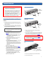
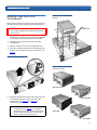
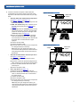
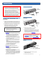
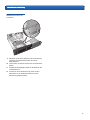
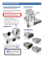
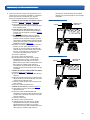
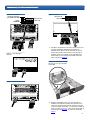
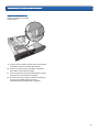
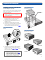
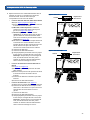
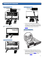
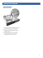
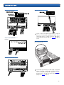
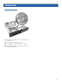
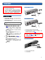
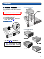
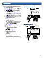
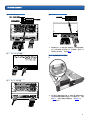
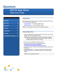
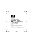
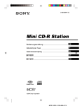
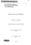
1
2U Rackmount
Quick Start Guide
CONTENTS
English ................................1
German ...............................7
Spanish ..............................13
French ................................19
Japanese ...........................25
Korean ...............................31
Simplified Chinese ............37
Introduction
0
This guide provides instructions for installing a 2U Rackmount enclosure into an
equipment rack, and for installing tape drives into the 2U Rackmount.
The 2U Rackmount accommodates the following tape drives: SDLT 320 (SCSI),
SDLT 600 (SCSI), SDLT 600 (Fibre Channel), DLT-S4 (SCSI), DLT-S4 (Fibre Channel),
and LTO-3 (SCSI).
The 2U Rackmount comes with either one or two tape drives installed. If yours
came with one, you may add another in the future, as long as both use the same
interface. See “Installing a Tape Drive in the 2U Rackmount” on page 3 for
instructions.
For More Information .......42
Installing the 2U Rackmount in an Equipment Rack
0
1 The packing box contains the 2U Rackmount enclosure, mounting kit, and
accessories.
2 Use the mounting kit to install the 2U Rackmount into your equipment rack.
Refer to the installation instructions included with mounting kit. See figure 1.
Figure 1 Front View of
Equipment Rack
2U Rackmount Quick Start Guide
WARNING: For maximum stability, the equipment rack
should be securely bolted to the floor per the rack
manufacturer’s recommendations.
Figure 2 SCSI Connections
SCSI
terminator
After installing components in the equipment rack,
do not pull out more than one component on its
slide rails at a time. If the equipment rack is not
securely bolted to the floor, the weight of more than
one extended component could cause the
equipment rack to become unstable, tip over, and
cause damage, serious bodily injury, or death.
Connecting the Interface and Power
Cables
SCSI
cable
Power cable
Figure 3 Fibre Channel
Connections
0
1 Shut down and turn off the selected host server. Turn
off all attached accessory devices, such as printers and
other SCSI devices.
2 Connect the interface and power cables to the back of
the 2U Rackmount, following the instructions below for
the type of interface you are using.
NOTE: Be sure to connect the cables on the same
side of the 2U Rackmount as the tape drive(s)
you will be using.
•
•
SCSI (SDLT 320, SDLT 600, DLT-S4, LTO-3) (see
figure 2)
a) Connect one end of the SCSI cable to one of the
SCSI connectors on the back of the
2U Rackmount. Connect the other end of the
SCSI cable to the host.
b) Connect the SCSI terminator to the adjacent
SCSI connector on the back of the 2U
Rackmount.
c) Each SCSI device must have its own unique SCSI
ID. Change SCSI ID(s) if necessary.
Note: Any time you change the SCSI ID, you
must turn the drive power off and then back on
using the power button on the front of the 2U
Rackmount.
d) Connect the power cable.
Fibre Channel (SDLT 600, DLT-S4) (see figure 3)
a) Remove the protective cap(s) from the Fibre
Channel port on the back of the 2U Rackmount.
b) Remove the protective covers from the ends of
the Fibre Channel cable.
c) Connect one end of the Fibre Channel cable to
the Fibre Channel port on the back of the
2U Rackmount. Connect the other end of the
Fibre Channel cable to the host.
d) Connect the power cable.
Fibre
Channel
cable
Power cable
3 Plug in the power cable to the nearest properly
grounded power outlet.
4 Turn on the 2U Rackmount by pressing and holding the
power button on the front panel for one second. The
green power LED should illuminate. See figure 4.
CAUTION: An illuminated fan LED (the left LED on the
front panel) indicates a fan failure (see figure 4).
Confirm that this has not occurred. If the fan LED is
illuminated, contact Quantum (www.quantum.com).
Figure 4 Power Button and Fan
LED
Power button
Power LED
Fan failure LED
5 Turn on any other devices you turned off earlier.
6 Turn on the host server.
2
2U Rackmount Quick Start Guide
Installing a Tape Drive in the
2U Rackmount
0
Figure 6 General Thumbscrew
locations
Follow these instructions to install a second tape drive or to
reinstall a tape drive after it has been removed for servicing.
Extra
thumbscrews
CAUTION: Before performing this procedure, you must
turn off the 2U Rackmount and disconnect it from its
power source.
1 Turn off the 2U Rackmount by pressing and holding the
power button on the front panel for three seconds.
2 Disconnect the power cable from the back of the
2U Rackmount.
3 Slide the 2U Rackmount out of the equipment rack.
4 Loosen the captive thumbscrews securing the top cover.
Slide the cover forward, then lift up to remove it. See
figure 5.
Figure 5 Removing the Top Cover
Figure 7 Specific Thumbscrew
Locations and Types
SDLT 320 (6-32)
5 Install two thumbscrews into the side of the tape drive
that will be located next to the outer wall of the
2U Rackmount. See figure 6 and figure 7 for
thumbscrew locations.
NOTE: Extra thumbscrews are stored inside the
2U Rackmount (see figure 6). Use the type
appropriate for your unit: SDLT 320 tape drives
use 6-32 (silver) thumbscrews; all other tape
drives use M3 (black) thumbscrews.
SDLT 600 (M3)
LTO-3 (M3)
DLT-S4 (M3)
3
2U Rackmount Quick Start Guide
6 Locate the interface and power cables inside the
2U Rackmount and connect them to the back of the
tape drive. Follow the instructions below for your tape
drive:
•
SDLT 320, SDLT 600, and DLT-S4 SCSI tape drives
(see figure 8, figure 9, and figure 10)
a) Remove all jumpers from the SCSI ID pins on the
back of the tape drive.
b) SDLT 320 and 600 only: Place a jumper on the
two left-most SCSI ID pins (see figure 8 and
figure 9).
c) DLT-S4 only: Place the TERMPWR jumper on two
left-most SCSI ID pins. Place the SCSI ID Enable
jumper on the two pins just to the right of the
TERMPWR jumper (see figure 10).
d) Attach the unlabeled 8-pin SCSI ID connector
with six multicolored wires to the eight rightmost SCSI ID pins on the tape drive. Ensure that
the brown wire is connected to the upper
right pin.
e) Connect the SCSI cable.
f) Connect the power cable.
g) Each SCSI device must have its own unique SCSI
ID. Change SCSI ID(s) if necessary.
Note: Any time you change the SCSI ID, you
must turn the drive power off and then back on
using the power button on the front of the 2U
Rackmount.
•
SDLT 600 and DLT-S4 Fibre Channel tape drives
(see figure 11 and figure 12)
a) Remove the protective caps from the Fibre
Channel cable.
b) If present, remove the protective plug from the
Fibre Channel port on the back of the tape drive.
c) Connect the Fibre Channel cable to the Fibre
Channel port.
d) Connect the power cable.
•
LTO-3 tape drives (see figure 13)
a) Remove all jumpers from the SCSI ID pins.
b) Connect the SCSI ID cable labeled “LTO1/LTO2-L/
LTO3” so that the brown wire is connected to
the upper left pin.
c) Connect the SCSI cable.
d) Connect the power cable.
e) Each SCSI device must have its own unique SCSI
ID. Change SCSI ID(s) if necessary.
Note: Any time you change the SCSI ID, you
must turn the drive power off and then back on
using the power button on the front of the 2U
Rackmount.
Figure 8 SDLT 320
Jumper
Brown wire
location
Figure 9 SDLT 600 SCSI
Jumper
Brown wire
location
4
2U Rackmount Quick Start Guide
Figure 10 DLT-S4 SCSI
SCSI ID Enable
Jumper
TERMPWR
Jumper
Figure 11 SDLT 600 Fibre
Channel
Figure 13 LTO-3
Brown wire
location
Brown wire
location
7 Lower the tape drive into the slot in the 2U Rackmount,
sliding the thumbscrews into the openings in the outer
wall of the 2U Rackmount. Slide the tape drive all the
way into the 2U Rackmount until it stops. See figure 14.
Figure 14 Sliding the Tape Drive
Into the 2U Rackmount
Figure 12 DLT-S4 Fibre Channel
8 Secure the tape drive to the 2U Rackmount by installing
two thumbscrews through the bottom set of mounting
holes in the inner wall of the 2U Rackmount and into
the tape drive. See figure 15. Use the correct
thumbscrew type (indicated in the Note for step 5).
5
2U Rackmount Quick Start Guide
Figure 15 Installing
Thumbscrews Through Inner Wall
9 Replace the 2U Rackmount top cover and tighten the
top cover thumbscrews.
10 Slide the 2U Rackmount back into the equipment rack.
11 Reconnect the power cable to the back of the
2U Rackmount.
12 Turn on the 2U Rackmount by pressing and holding the
power button on the front panel for one second.
6
2U Rackmount
Kurzanleitung
INHALT
Englisch ...............................1
Deutsch................................7
Spanisch.............................13
Französisch ........................19
Japanisch ...........................25
Koreanisch .........................31
Vereinfachtes Chinesisch ....37
Weitere Informationen .....42
Einführung
0
Dieses Handbuch enthält Anleitungen zur Installation eines 2U Rackmount-Gehäuses
in ein Geräte-Rack und zur Installation von Bandlaufwerken in das 2U Rackmount.
Das 2U Rackmount ist für die folgenden Bandlaufwerke konzipiert: SDLT 320
(SCSI), SDLT 600 (SCSI), SDLT 600 (Fibre Channel), DLT-S4 (SCSI), DLT-S4 (Fibre
Channel) und LTO-3 (SCSI).
Das 2U Rackmount wird entweder mit einem oder mit zwei installierten
Bandlaufwerken geliefert. Wenn Ihres mit einem Bandlaufwerk geliefert wurde,
können Sie in Zukunft ein weiteres hinzufügen, solange beide die gleiche
Schnittstelle verwenden. Anleitungen hierzu erhalten Sie unter “Installation eines
Bandlaufwerks in das 2U Rackmount” auf Seite 9.
Installation des 2U Rackmount in ein Geräte-Rack
0
1 Die Verpackungskiste enthält das 2U Rackmount-Gehäuse, Montage-Kit und Zubehör.
2 Verwenden Sie das Montage-Kit zur Installation des 2U Rackmount in Ihrem
Geräte-Rack. Lesen Sie die mit dem Montage-Kit gelieferten
Installationsanleitungen. Siehe Abbildung 1.
Abbildung 1 Vorderansicht
des Geräte-Racks
2U Rackmount Kurzanleitung
WARNUNG: Um maximale Stabilität zu erreichen, sollte das
Geräte-Rack gemäß den Empfehlungen des RackHerstellers fest in den Boden geschraubt werden.
Abbildung 2 SCSI-Verbindungen
SCSITerminator
Nach der Installation der Komponenten in das GeräteRack sollten Sie nicht mehr als jeweils eine
Komponente auf den Laufschienen herausziehen.
Wenn das Geräte-Rack nicht sicher in den Boden
geschraubt ist, könnte das Gewicht von mehr als einer
herausgezogenen Komponente verursachen, dass das
Geräte-Rack unstabil wird, umkippt und Schaden,
schwere Körperverletzung oder Tod zur Folge hat.
Anschluss der Schnittstellen- und
Netzkabel
SCSIKabel
Netzkabel
Abbildung 3 Fibre ChannelVerbindungen
0
1 Fahren Sie den ausgewählten Hostserver herunter, und
schalten Sie ihn aus. Schalten Sie alle angeschlossenen
Zubehörgeräte wie Drucker und andere SCSI-Geräte aus.
2 Schließen Sie die Schnittstellen- und Netzkabel an die
Rückseite des 2U Rackmount an, indem Sie die
untenstehenden Anleitungen für die von Ihnen
verwendete Art von Schnittstelle befolgen.
ANMERKUNG: Stellen Sie sicher, dass Sie die Kabel auf
der gleichen Seite des 2U Rackmount
anschließen wie das/die Bandlaufwerk(e), das/
die Sie verwenden werden.
•
•
SCSI (SDLT 320, SDLT 600, DLT-S4, LTO-3) (siehe
Abbildung 2)
a) Schließen Sie ein Ende des SCSI-Kabels an einen
der SCSI-Anschlüsse an der Rückseite des
2U Rackmount an. Schließen Sie das andere
Ende des SCSI-Kabels an den Host an.
b) Schließen Sie den SCSI-Terminator an den danebenliegenden SCSI-Steckverbinder an der Rückseite des 2U Rackmount an.
c) Jedes SCSI-Gerät muss eine eindeutige SCSI-ID
besitzen. Ändern Sie die SCSI-ID(s), falls erforderlich.
Anmerkung: Jedes Mal, wenn Sie die SCSI-ID
ändern, muss das Laufwerk mit dem Netzschalter an der Vorderseite des 2U Rackmount ausund wieder eingeschaltet werden.
d) Schließen Sie das Netzkabel an.
Fibre Channel (SDLT 600, DLT-S4) (siehe
Abbildung 3)
a) Entfernen Sie die Schutzkappe(n) vom Fibre
Channel-Anschluss an der Rückseite des
2U Rackmount.
b) Entfernen Sie die Schutzabdeckungen von den
Enden des Fibre Channel-Kabels.
c) Schließen Sie ein Ende des Fibre Channel-Kabels
an den Fibre Channel-Anschluss an der Rückseite
des 2U Rackmount an. Schließen Sie das andere
Ende des Fibre Channel-Kabels an den Host an.
d) Schließen Sie das Netzkabel an.
Fibre
ChannelKabel
Netzkabel
3 Stecken Sie das Netzkabel in die nächste
ordnungsgemäß geerdete Steckdose.
4 Schalten Sie das 2U Rackmount ein, indem Sie den
Netzschalter an der Vorderseite drücken und eine
Sekunde lang gedrückt halten. Die grüne Netz-LED
sollte aufleuchten. Siehe Abbildung 4.
VORSICHT: Eine leuchtende Lüfter-LED (die linke LED an
der Vorderseite) zeigt einen Lüfterfehler an (siehe
Abbildung 4). Bestätigen Sie, dass dies nicht
eingetreten ist. Wenn die Lüfter-LED leuchtet,
kontaktieren Sie Quantum (www.quantum.com).
Abbildung 4 Netzschalter- und
Lüfter-LED
Netzschalter
Netz-LED
Lüfterfehler-LED
5 Schalten Sie alle anderen Geräte ein, die Sie
ausgeschaltet hatten.
6 Schalten Sie den Hostserver ein.
8
2U Rackmount Kurzanleitung
Installation eines Bandlaufwerks in das
0
2U Rackmount
Abbildung 6 Allgemeine
Positionen von Rändelschrauben
Folgen Sie diesen Anleitungen, um ein zweites Bandlaufwerk
zu installieren, oder um ein Bandlaufwerk neu zu installieren,
nachdem dieses zur Wartung entfernt worden war.
Zusätzliche
Rändelschrauben
VORSICHT: Vor dem Ausführen dieses Verfahrens muss
das 2U Rackmount ausgeschaltet und von der
Stromquelle getrennt werden.
1 Schalten Sie das 2U Rackmount aus, indem Sie den
Netzschalter an der Vorderseite drücken und drei
Sekunden lang gedrückt halten.
2 Trennen Sie das Netzkabel von der Rückseite des
2U Rackmount.
3 Lassen Sie das 2U Rackmount aus dem Geräte-Rack gleiten.
4 Lösen Sie die unverlierbaren Rändelschrauben, die zur
Befestigung der Abdeckung dienen. Ziehen Sie die
Abdeckung nach vorne und dann nach oben, um sie
abzunehmen. Siehe Abbildung 5.
Abbildung 5 Obere Abdeckung
entfernen
Abbildung 7 Spezifische
Positionen und Typen von
Rändelschrauben
SDLT 320 (6-32)
SDLT 600 (M3)
5 Installieren Sie zwei Rändelschrauben in die Seite des
Bandlaufwerks, die sich neben der Außenwand des
2U Rackmount befindet. Die Position der Rändelschrauben
entnehmen Sie Abbildung 6 und Abbildung 7.
ANMERKUNG: Zusätzliche Rändelschrauben werden
innerhalb des 2U Rackmount aufbewahrt (siehe
Abbildung 6). Verwenden Sie den entsprechenden Typ für Ihr Gerät: SDLT 320-Bandlaufwerke
verwenden 6-32-Rändelschrauben (silberfarben); für alle anderen Bandlaufwerke werden
M3-Rändelschrauben (schwarz) verwendet.
LTO-3 (M3)
DLT-S4 (M3)
9
2U Rackmount Kurzanleitung
6 Machen Sie die Schnittstellen- und Netzkabel im
2U Rackmount ausfindig, und schließen Sie sie an die
Rückseite des Bandlaufwerks an. Folgen Sie den
untenstehenden Anleitungen für Ihr Bandlaufwerk:
•
SDLT 320-, SDLT 600- und DLT-S4-SCSIBandlaufwerke (siehe Abbildung 8, Abbildung 9
und Abbildung 10)
a) Entfernen Sie alle Jumper von den SCSI-IDStiften auf der Rückseite des Bandlaufwerks.
b) Nur SDLT 320 und 600: Bringen Sie auf den
beiden SCSI-ID-Pins, die sich ganz links befinden,
einen Jumper an (siehe Abbildung 8 und
Abbildung 9).
c) Nur DLT-S4: Bringen Sie auf den beiden SCSI-IDPins, die sich ganz links befinden, den
TERMPWR-Jumper an. Platzieren Sie die SCSI-ID
Aktivieren Sie den Jumper auf den beiden Pins,
die sich unmittelbar rechts neben dem
Abschlusswiderstandsstrom-Jumper befinden
(siehe Abbildung 10).
d) Schließen Sie den nichtmarkierten 8-Pin-SCSI-IDAnschluss mit sechs verschiedenfarbigen
Drähten an die acht SCSI-ID-Pins an, die sich auf
dem Bandlaufwerk ganz rechts befinden. Stellen
Sie sicher, dass der braune Draht mit dem
oberen rechten Pin verbunden ist.
e) Schließen Sie das SCSI-Kabel an.
f) Schließen Sie das Netzkabel an.
g) Jedes SCSI-Gerät muss eine eindeutige SCSI-ID
besitzen. Ändern Sie die SCSI-ID(s), falls
erforderlich.
Anmerkung: Jedes Mal, wenn Sie die SCSI-ID
ändern, muss das Laufwerk mit dem
Netzschalter aus- und wieder eingeschaltet
werden, der sich an der Vorderseite des 2U
Rackmount befindet.
•
SDLT 600- und DLT-S4-Fibre ChannelBandlaufwerke
(siehe Abbildung 11 und Abbildung 12)
a) Entfernen Sie die Schutzkappen vom Fibre
Channel-Kabel.
b) Falls vorhanden, entfernen Sie den Schutzstecker
vom Fibre Channel-Anschluss auf der Rückseite
des Bandlaufwerks.
c) Schließen Sie das Fibre Channel-Kabel an den
Fibre Channel-Anschluss an.
d) Schließen Sie das Netzkabel an.
•
LTO-3-Bandlaufwerke (siehe Abbildung 13)
a) Entfernen Sie alle Jumper von den SCSI-ID-Pins.
b) Verbinden Sie das mit “LTO1/LTO2-L/LTO3”
markierte SCSI-ID-Kabel so, dass der braune
Draht mit dem oberen linken Pin verbunden ist.
c) Schließen Sie das SCSI-Kabel an.
d) Schließen Sie das Netzkabel an.
e) Jedes SCSI-Gerät muss eine eindeutige SCSI-ID
besitzen. Ändern Sie die SCSI-ID(s), falls
erforderlich.
Anmerkung: Jedes Mal, wenn Sie die SCSI-ID
ändern, muss das Laufwerk mit dem Netzschalter
an der Vorderseite des 2U Rackmount aus- und
wieder eingeschaltet werden.
Abbildung 8 SDLT 320
Jumper
Position des
braunen Drahtes
Abbildung 9 SDLT 600 SCSI
Jumper
Position des
braunen Drahtes
10
2U Rackmount Kurzanleitung
Abbildung 10 DLT-S4 SCSI
SCSI-ID Jumper
aktivieren
Abschlusswiderstandsstrom-Jumper
Abbildung 11 SDLT 600-Fibre
Channel
Abbildung 13 LTO-3
Position des
braunen
Drahtes
Position des
braunen Drahtes
7 Senken Sie das Bandlaufwerk in die Einbaustelle im
2U Rackmount, und schieben Sie die Rändelschrauben
in die Öffnungen in der Außenwand des 2U
Rackmount. Schieben Sie das Bandlaufwerk ganz in das
2U Rackmount ein, bis es stoppt. Siehe Abbildung 14.
Abbildung 14 Bandlaufwerk in
das 2U Rackmount schieben
Abbildung 12 DLT-S4-Fibre
Channel
8 Sichern Sie das Bandlaufwerk am 2U Rackmount, indem
Sie zwei Rändelschrauben durch die Montagelöcher im
Boden der Innenwand des 2U Rackmount und in das
Bandlaufwerk einführen. Siehe Abbildung 15.
Verwenden Sie den richtigen Rändelschraubentyp
(angezeigt in der Anmerkung für Schritt 5).
11
2U Rackmount Kurzanleitung
Abbildung 15 Installieren von
Rändelschrauben durch die
Innenwand
9 Befestigen Sie die obere Abdeckung des 2U Rackmount,
und ziehen Sie die Rändelschrauben der oberen
Abdeckung fest.
10 Lassen Sie das 2U Rackmount zurück in das Geräte-Rack
gleiten.
11 Schließen Sie das Netzkabel wieder an die Rückseite des
2U Rackmount an.
12 Schalten Sie das 2U Rackmount ein, indem Sie den
Netzschalter an der Vorderseite drücken und eine
Sekunde lang gedrückt halten.
12
2U para montaje en bastidor
Manual de referencia
CONTENIDO
Inglés ...................................1
Alemán.................................7
Español ..............................13
Francés...............................19
Japonés..............................25
Coreano .............................31
Chino simplificado ............37
Introducción
0
Esta guía contiene instrucciones para instalar el gabinete del 2U para montaje en
bastidor de equipo, así como para instalar unidades de cinta en el 2U para montaje
en bastidor.
En el 2U para montaje en bastidor se pueden utilizar las siguientes unidades de
cinta: SDLT 320 (SCSI), SDLT 600 (SCSI), SDLT 600 (Fibre Channel), DLT-S4 (SCSI),
DLT-S4 (Fibre Channel) y LTO-3 (SCSI).
El 2U para montaje en bastidor se entrega con una o bien dos unidades de cinta
previamente instaladas. Si el suyo tiene una, puede agregar otra en el futuro, siempre
y cuando ambas utilicen la misma interfaz. Consulte “Instalación de la unidad de
cinta en el 2U para montaje en bastidor” en la página 15 para obtener instrucciones.
Para obtener más
información .......................42
Cómo instalar el 2U para montaje en bastidor en un
0
bastidor de equipo
1 La caja de embalaje contiene el gabinete del 2U para montaje en bastidor, el
kit de montaje y los accesorios.
2 Utilice el kit de montaje para instalar el 2U para montaje en bastidor en un
bastidor de equipo. Consulte las instrucciones de instalación incluidas en el kit
de montaje. Consulte la figura 1.
Figura 1 Vista frontal del
bastidor del equipo
2U para montaje en bastidor. Manual de referencia
ADVERTENCIA: Para mayor estabilidad, el bastidor del
equipo debe estar firmemente atornillado al piso
conforme a las recomendaciones del fabricante del
bastidor.
Una vez que los componentes estén instalados en el
bastidor del equipo, no saque más de un componente a la
vez por medio de los rieles deslizables. Cuando el bastidor
del equipo no está firmemente atornillado al piso, el peso
de más de un componente saliendo del bastidor puede
ocasionar que éste pierda estabilidad y se caiga,
ocasionando lesiones físicas graves o incluso la muerte.
Conexión de los cables de interfaz y de
0
alimentación
Figura 2 Conexiones SCSI
Terminador
SCSI
Cable
SCSI
Cable de
alimentación
Figura 3 Conexiones Fibre
Channel
1 Cierre y apague el servidor principal seleccionado.
Apague todos los dispositivos accesorios conectados,
como impresoras y otros dispositivos SCSI.
2 Conecte los cables de interfaz y de alimentación en la
parte posterior del 2U para montaje en bastidor,
siguiendo las instrucciones a continuación para el tipo
de interfaz que utilice.
NOTA: Asegúrese de conectar los cables en el mismo
lado del 2U para montaje en bastidor y de la(s)
unidad(es) de cinta que utilizará.
•
•
SCSI (SDLT 320, SDLT 600, DLT-S4, LTO-3)
(consulte la figura 2)
a) Conecte un extremo del cable SCSI a uno de los
conectores SCSI ubicados en la parte posterior
del 2U para montaje en bastidor. Conecte el otro
extremo del cable SCSI en el equipo host.
b) Conecte el terminador SCSI en el conector SCSI
adyacente ubicado en la parte posterior del 2U
para montaje en bastidor.
c) Cada dispositivo SCSI debe tener su propio
identificador SCSI exclusivo. Cambie el(los)
identificador(es) SCSI según sea necesario.
Nota: Cada vez que cambie el identificador SCSI,
debe apagar la unidad y luego volverla a encender
por medio del botón de encendido ubicado en la
parte frontal del 2U para montaje en bastidor.
d) Conecte el cable de alimentación.
Fibre Channel (SDLT 600, DLT-S4) (consulte la
figura 3)
a) Quite la(s) tapa(s) de protección del puerto de
Fibre Channel ubicado en la parte posterior del
2U para montaje en bastidor.
b) Quite las cubiertas de protección de los
extremos del cable de Fibre Channel.
c) Conecte un extremo del cable de Fibre Channel
en el puerto de Fibre Channel ubicado en la
parte posterior del 2U para montaje en bastidor.
Conecte el otro extremo del cable de Fibre
Channel en el equipo host.
d) Conecte el cable de alimentación.
Cable de
Fibre
Channel
Cable de
alimentación
3 Enchufe el cable de alimentación al toma corriente con
toma a tierra más cercano.
4 Encienda el 2U para montaje en bastidor presionando
el botón de encendido del panel frontal y
manteniéndolo oprimido durante un segundo. El
indicador LED de encendido color verde se deberá
iluminar. Consulte la figura 4.
PRECAUCIÓN: Cuando el indicador LED del ventilador (el
indicador LED ubicado en la parte izquierda del panel
frontal) está iluminado significa que hay una falla
(consulte la figura 4). Compruebe que esto no haya
ocurrido. En caso que el indicador LED del ventilador esté
iluminado, contacte a Quantum (www.quantum.com).
Figura 4 Botón de encendido e
indicador LED del ventilador
Botón de
encendido
Indicador LED de
encendido
Indicador LED de
falla del
ventilador
5 Encienda los dispositivos que apagó previamente.
6 Encienda el servidor principal.
14
2U para montaje en bastidor. Manual de referencia
Instalación de la unidad de cinta en el
0
2U para montaje en bastidor
Figura 6 Ubicación general de
los tornillos de palometa
Siga estas instrucciones para instalar una segunda unidad
de cinta o para volver a instalar una unidad de cinta después
de haberla retirado para servicio.
Tornillos de
palometa
adicionales
PRECAUCIÓN: Antes de realizar este procedimiento, debe
apagar el 2U para montaje en bastidor y
desconectarlo de la fuente de alimentación.
1 Apague el 2U para montaje en bastidor presionando el
botón de encendido del panel frontal y manteniéndolo
oprimido durante tres segundos.
2 Desconecte el cable de alimentación de la parte
posterior del 2U para montaje en bastidor.
3 Deslice el 2U para montaje en bastidor al interior del
bastidor de equipo.
4 Afloje los tornillos de palometa que fijan la cubierta
superior. Deslice la cubierta hacia adelante, luego
levántela para quitarla. Consulte la figura 5.
Figura 5 Desmontaje de la
cubierta superior
Figura 7 Ubicación específica y
tipos de tornillos de palometa
SDLT 320 (6-32)
SDLT 600 (M3)
5 Introduzca dos tornillos de palometa en el costado de la
unidad de cinta que estará junto al costado externo del
2U para montaje en bastidor. Consulte la figura 6 y la
figura 7 para ver la ubicación de los tornillos de palometa.
NOTA: En el interior del 2U para montaje en bastidor
hay tornillos de palometa adicionales (consulte
la figura 6). Utilice el tipo apropiado para su
unidad: las unidades de cinta SDLT 320 utilizan
tornillos de palometa 6-32 (color plata); las
unidades de cinta restantes utilizan tornillos de
palometa M3 (color negro).
LTO-3 (M3)
DLT-S4 (M3)
15
2U para montaje en bastidor. Manual de referencia
6 Localice los cables de interfaz y de alimentación en el
interior del 2U para montaje en bastidor y conéctelos a
la parte posterior de la unidad de cinta. Siga las
instrucciones siguientes para su unidad de cinta:
•
•
•
Unidades de cinta SCSI SDLT 320, SDLT 600 y DLT-S4
(consulte la figura 8, la figura 9 y la figura 10)
a) Quite todos los puentes de las patillas del
identificador SCSI ubicadas en la parte posterior
de la unidad de cinta.
b) Para SDLT 320 y 600 solamente: coloque un
puente sobre las dos patillas del identificador
SCSI del extremo izquierdo (consulte la figura 8
y la figura 9).
c) Para DLT-S4 solamente: coloque el puente
TERMPWR sobre las patillas del identificador
SCSI del extremo izquierdo. Coloque el puente
de activación del identificador SCSI sobre las dos
patillas que están justo a la derecha del puente
TERMPWR (consulte la figura 10).
d) Coloque el conector del identificador SCSI de 8
patillas, con seis cables multicolores y sin
etiqueta, en las ocho patillas del identificador
SCSI ubicadas al extremo derecho de la unidad
de cinta. Compruebe que el cable café esté
conectado a la patilla superior derecha.
e) Conecte el cable SCSI.
f) Conecte el cable de alimentación.
g) Cada dispositivo SCSI debe tener su propio
identificador SCSI exclusivo. Cambie el(los)
identificador(es) SCSI según sea necesario.
Nota: Cada vez que cambie el identificador SCSI,
debe apagar la unidad y luego volverla a
encender por medio del botón de encendido
ubicado en la parte frontal del 2U para montaje
en bastidor.
Unidades de cinta Fibre Channel SDLT 600 y DLT-S4
(consulte la figura 11 y la figura 12)
a) Quite las tapas de protección del cable de Fibre
Channel.
b) Quite el tapón de protección (en caso que esté)
del puerto de Fibre Channel ubicado en la parte
posterior de la unidad de cinta.
c) Conecte el cable de Fibre Channel al puerto de
Fibre Channel.
d) Conecte el cable de alimentación.
Unidades de cinta LTO-3 (consulte la figura 13)
a) Quite todos los puentes de las patillas del
identificador SCSI.
b) Conecte el cable del identificador SCSI
etiquetado “LTO1/LTO2-L/LTO3” de tal forma que
el cable color café quede conectado a la patilla
superior izquierda.
c) Conecte el cable SCSI.
d) Conecte el cable de alimentación.
e) Cada dispositivo SCSI debe tener su propio
identificador SCSI exclusivo. Cambie el(los)
identificador(es) SCSI según sea necesario.
Nota: Cada vez que cambie el identificador SCSI,
debe apagar la unidad y luego volverla a
encender por medio del botón de encendido
ubicado en la parte frontal del 2U para montaje
en bastidor.
Figura 8 SDLT 320
Puente
Ubicación del
cable café
Figura 9 SDLT 600 SCSI
Puente
Ubicación del
cable café
16
2U para montaje en bastidor. Manual de referencia
Figura 10 DLT-S4 SCSI
Puente de activación
del identificador SCSI
Puente
TERMPWR
Figura 11 SDLT 600 Fibre
Channel
Figura 13 LTO-3
Ubicación del
cable café
Ubicación del
cable café
7 Introduzca la unidad de cinta en la ranura del 2U para
montaje en bastidor, deslizando los tornillos de
palometa hacia adentro de las aberturas de la parte
exterior del costado externo del 2U para montaje en
bastidor. Deslice la unidad de cinta completamente
adentro del 2U para montaje en bastidor hasta que
tope. Consulte la figura 14.
Figura 14 Inserción de la unidad
de cinta en el 2U para montaje
en bastidor
Figura 12 DLT-S4 Fibre Channel
8 Asegure la unidad de cinta al 2U para montaje en
bastidor insertando dos tornillos de palometa en los
orificios de montaje inferiores del costado interior del
2U para montaje en bastidor y a través de la unidad de
cinta. Consulte la figura 15. Utilice el tipo de tornillo de
palometa apropiado (según se indica en la Nota del
paso 5).
17
2U para montaje en bastidor. Manual de referencia
Figura 15 Inserción de los
tornillos de palometa a través del
costado interno
9 Vuelva a poner la cubierta superior del 2U para montaje
en bastidor y apriete los tornillos de palometa.
10 Deslice el 2U para montaje en bastidor nuevamente
hacia adentro del bastidor de equipo.
11 Conecte nuevamente el cable de alimentación a la parte
posterior del 2U para montaje en bastidor.
12 Encienda el 2U para montaje en bastidor presionando
el botón de encendido del panel frontal y
manteniéndolo oprimido durante un segundo.
18
Montage en rack 2U
Guide de démarrage rapide
SOMMAIRE
Anglais .................................1
Allemand .............................7
Espagnol ............................13
Français..............................19
Japonais.............................25
Coréen ...............................31
Chinois simplifié ...............37
Pour plus d'informations ....42
Introduction
0
Ce guide fournit des instructions pour installer une enceinte de montage en rack
2U dans un rack et des lecteurs de bande dans un montage en rack 2U.
Le montage en rack 2U peut héberger les lecteurs de bande suivants : SDLT 320
(SCSI), SDLT 600 (SCSI), SDLT 600 (Fibre Channel), DLT-S4 (SCSI), DLT-S4 (Fibre
Channel) et LTO-3 (SCSI).
Le montage en rack 2U est disponible avec un ou deux lecteurs de bande installés.
Si le vôtre est livré avec un seul lecteur de bande, vous pouvez en rajouter un
second ultérieurement du moment qu'ils utilisent tous les deux la même interface.
Reportez-vous à « Installation du lecteur de bande dans un montage en rack 2U »,
page 21 pour des instructions.
Installation du montage en rack 2U dans un rack
0
1 Le carton d'emballage contient l'enceinte du montage en rack 2U, le kit de
montage et les accessoires.
2 Utilisez le kit de montage pour installer le montage en rack 2U dans votre rack.
Veuillez consulter les instructions d'installation fournies avec le kit de
montage. Voir figure 1.
Figure 1 Vue de l'avant du rack
Montage en rack 2U Guide de démarrage rapide
AVERTISSEMENT : Pour un maximum de stabilité, le rack
doit être bien fixé au sol à l'aide de boulons selon les
recommandations du fabriquant du rack.
Figure 2 Connexions SCSI
Terminateur
SCSI
Une fois les composants installés dans le rack, ne
retirez pas plus d'un composant à la fois sur les rails
à glissières. Si le rack n'est pas rattaché au sol avec
des boulons, le poids de plus d'un composant
étendu risquerait de rendre le rack instable et de le
faire chavirer, ce qui pourrait causer des dommages,
des blessures importantes ou même la mort.
Branchement de l'interface et des
câbles d'alimentation
Câble
SCSI
Câble
d'alimentation
Figure 3 Connexions Fibre
Channel
0
1 Arrêtez et mettez hors tension le serveur hôte
sélectionné. Éteignez tous les périphériques auxiliaires
reliés, comme les imprimantes et les autres
périphériques SCSI.
2 Connectez l'interface et les câbles d'alimentations à
l'arrière du montage en rack 2U en suivant les
instructions correspondant au type d'interface que vous
utilisez.
REMARQUE : Assurez-vous que les câbles sont
connectés du même côté du montage en rack
2U que le lecteur de bande que vous utiliserez.
•
•
SCSI (SDLT 320, SDLT 600, DLT-S4, LTO-3) (voir
figure 2)
a) Connectez une extrémité du câble SCSI à un des
connecteurs SCSI à l'arrière du montage en rack
2U. Raccordez l'autre extrémité du câble SCSI à
l'hôte.
b) Raccordez le terminateur SCSI au connecteur
SCSI adjacent à l'arrière du montage en rack 2U.
c) Chaque périphérique SCSI doit avoir son propre
ID SCSI unique. Changez l'ID SCSI si nécessaire.
Remarque : Chaque fois que vous changez l'ID
SCSI, vous devez éteindre le lecteur puis le
rallumer en utilisant le bouton d'alimentation
situé à l'avant du montage en rack 2U.
d) Connectez le câble d'alimentation.
Fibre Channel (SDLT 600, DLT-S4) (voir figure 3)
a) Retirez les capuchons de protection du port
Fibre Channel à l'arrière du montage en rack 2U.
b) Retirez les capuchons de protection des
extrémités du câble Fibre Channel.
c) Connectez une extrémité du câble Fibre Channel
au port Fibre Channel à l'arrière du montage en
rack 2U. Raccordez l'autre extrémité du câble
Fibre Channel à l'hôte.
d) Connectez le câble d'alimentation.
Câble Fibre
Channel
Câble
d'alimentation
3 Branchez le câble d'alimentation dans la prise reliée à la
terre la plus proche.
4 Mettez le montage en rack 2U sous tension en
appuyant pendant une seconde sur le bouton
d'alimentation situé sur le panneau avant. Le voyant
DEL d'alimentation vert devrait s'allumer. Voir figure 4.
ATTENTION ! Un voyant DEL du ventilateur allumé (Le
voyant DEL gauche du panneau avant) indique un
échec du ventilateur (voir figure 4). Confirmez que
ceci n'est pas survenu. Si le voyant DEL du ventilateur
est allumé, contactez Quantum (www.quantum.com).
Figure 4 Bouton d'alimentation
et voyant DEL du ventilateur
Bouton
d'alimentation
Voyant DEL
d'alimentation
Voyant DEL d'échec
du ventilateur
5 Allumez les autres périphériques que vous aviez éteints
précédemment.
6 Allumez le serveur hôte.
20
Montage en rack 2U Guide de démarrage rapide
Installation du lecteur de bande dans
un montage en rack 2U
0
Figure 6 Emplacements
généraux des vis à oreilles
Suivez ces instructions pour installer un deuxième lecteur de
bande ou pour réinstaller un lecteur de bande qui a été
retiré pour des réparations.
Vis à oreilles
supplémentaires
ATTENTION ! Avant d'effectuer cette procédure, mettez le
montage en rack 2U hors tension et débranchez-le de
sa source d'alimentation.
1 Mettez le montage en rack 2U hors tension en
appuyant pendant trois secondes sur le bouton
d'alimentation situé sur le panneau avant.
2 Déconnectez le câble d'alimentation de l'arrière du
montage en rack 2U.
3 Faites glisser le montage en rack 2U hors du rack.
4 Desserrez les vis à oreilles imperdables qui maintiennent
le panneau supérieur. Faites glisser le panneau vers
l'avant, puis tirez vers le haut pour le retirer. Voir figure 5.
Figure 5 Retrait du panneau
supérieur
Figure 7 Types et emplacements
spécifiques des vis à oreilles
SDLT 320 (6-32)
SDLT 600 (M3)
5 Installez deux vis à oreilles dans le côté du lecteur de
bande qui est situé du côté de la paroi externe du
montage en rack 2U. Voir figure 6 et figure 7 pour les
emplacements des vis à oreilles.
REMARQUE : Des vis à oreilles supplémentaires sont
situées dans le montage en rack 2U (voir figure 6).
Utilisez le type approprié pour votre unité : les
lecteurs de bande SDLT 320 utilisent des vis à
oreilles 6-32 (argent) ; tous les autres lecteurs de
bande utilisent des vis à oreilles M3 (noires) .
LTO-3 (M3)
DLT-S4 (M3)
21
Montage en rack 2U Guide de démarrage rapide
6 Repérez l'interface et les câbles d'alimentation dans le
montage en rack 2U et raccordez-les à l'arrière du
lecteur de bande. Suivez les instructions qui
correspondent à votre lecteur de bande :
•
Lecteurs de bande SDLT 320, SDLT 600 et DLT-S4
SCSI (voir figure 8, figure 9 et figure 10)
a) Retirez tous les cavaliers des broches de l'ID SCSI
à l'arrière du lecteur de bande.
b) SDLT 320 et 600 uniquement : mettez un
cavalier sur les broches de l'ID SCSI les plus à
gauche (voir figure 8 et figure 9).
c) DLT-S4 uniquement : mettez le cavalier
TERMPWR sur les broches de l'ID SCSI les plus à
gauche. Mettez le cavalier d'activation de l'ID
SCSI sur les broches les plus à droite du cavalier
TERMPWR (voir figure 10).
d) Raccordez le connecteur non marqué de l'ID SCSI
à huit broches à six fils multicolores aux huit
broches d'ID SCSI les plus à droite du lecteur de
bande. Assurez-vous que le fil marron est
connecté à la broche située en haut à droite.
e) Connectez le câble SCSI.
f) Connectez le câble d'alimentation.
g) Chaque périphérique SCSI doit avoir son propre
ID SCSI unique. Changez l'ID SCSI si nécessaire.
Remarque : Chaque fois que vous changez l'ID
SCSI, vous devez éteindre le lecteur puis le
rallumer en utilisant le bouton d'alimentation
situé à l'avant du montage en rack 2U.
•
Lecteurs de bande Fibre Channel SDLT 600 et
DLT-S4
(voir figure 11 et figure 12)
a) Retirez les capuchons de protection du câble
Fibre Channel.
b) Retirez la fiche protectrice du port Fibre Channel
à l'arrière du lecteur de bande si elle est
présente.
c) Connectez le câble Fibre Channel au port Fibre
Channel.
d) Connectez le câble d'alimentation.
•
Lecteurs de bande LTO-3 (voir figure 13)
a) Retirez tous les cavaliers des broches de l'ID SCSI.
b) Connectez le câble de l'ID SCSI marqué « LTO1/
LTO2-L/LTO3 » de manière à ce que le fil marron
s'enfiche dans la broche située en haut à
gauche.
c) Connectez le câble SCSI.
d) Connectez le câble d'alimentation.
e) Chaque périphérique SCSI doit avoir son propre
ID SCSI unique. Changez l'ID SCSI si nécessaire.
Remarque : Chaque fois que vous changez l'ID
SCSI, vous devez éteindre le lecteur puis le
rallumer en utilisant le bouton d'alimentation
situé à l'avant du montage en rack 2U.
Figure 8 SDLT 320
Cavalier
Emplacement
du fil marron
Figure 9 SCSI SDLT 600
Cavalier
Emplacement
du fil marron
22
Montage en rack 2U Guide de démarrage rapide
Figure 10 SCSI DLT-S4
Cavalier d'activation
de l'ID SCSI
Cavalier
TERMPWR
Figure 11 Fibre Channel SDLT
600
Figure 13 LTO-3
Emplacement
du fil marron
Emplacement
du fil marron
7 Insérez le lecteur de bande dans le logement du
montage en rack 2U, en glissant les vis à oreilles dans
les ouvertures de la paroi externe du montage en rack
2U. Faites glisser le lecteur de bande jusqu'au fond du
montage en rack 2U jusqu'à ce qu'il bute. Voir
figure 14.
Figure 14 Insertion du lecteur de
bande dans un montage en rack
2U
Figure 12 Fibre Channel DLT-S4
8 Fixez le lecteur de bande au montage en rack 2U en
installant deux vis à oreilles dans les trous de montage
inférieurs de la paroi interne du montage en rack 2U et
dans le lecteur de bande Voir figure 15. Utilisez le type
de vis à oreilles adéquat (indiqué dans la section
Remarque pour l'étape 5).
23
Montage en rack 2U Guide de démarrage rapide
Figure 15 Installation de vis à
oreilles dans la paroi interne
9 Remettez en place le panneau supérieur du montage en
rack 2U et serrez les vis à oreilles du panneau.
10 Faites glisser le montage en rack 2U dans le rack.
11 Reconnectez le câble d'alimentation à l'arrière du
montage en rack 2U.
12 Mettez le montage en rack 2U sous tension en
appuyant pendant une seconde sur le bouton
d'alimentation situé sur le panneau avant.
24
2U ラックマウント
クイック スタート ガイド
目次
英語........................ 1
ドイツ語.................... 7
スペイン語................. 13
フランス語................. 19
日本語..................... 25
韓国語..................... 31
中国語(簡体字)............ 37
はじめに
0
このガイドでは、2U ラックマウント エンクロージャを装置ラックに取り付ける手
順と、2U ラックマウントにテープ ドライブを装着する手順を説明します。
2U ラックマウントに対応しているテープ ドライブは、SDLT 320 (SCSI)、
SDLT 600 (SCSI)、SDLT 600 (Fibre Channel)、DLT-S4 (SCSI)、DLT-S4 (Fibre
Channel)、LTO-3 (SCSI) です。
2U ラックマウントにはテープ ドライブが 1 つまたは 2 つ搭載されています。1
つの場合は後でもう 1 つ追加できますが、両方が同じインターフェイスを使用し
ている必要があります。手順については、27 ページの「2U ラックマウントへの
テープ ドライブの装着」を参照してください。
詳細について............... 42
装置ラックへの 2U ラックマウントの取り付け
0
1 パッケージの箱には、2U ラックマウント エンクロージャ、取り付けキット、
および付属品が入っています。
2 取り付けキットを使用して 2U ラックマウントを装置のラックに取り付けま
す。取り付けキットに同梱の説明書を参照してください。図 1 を参照してく
ださい。
図 1
装置ラックの前面図
2U ラックマウント クイック スタート ガイド
警告:最大限の安定性を確保するため、装置ラックは製
造元の推奨に従って、ボルトで床にしっかりと固定
してください。
図 2
SCSI ター
ミネータ
装置のラックにコンポーネントを取り付けたあとで、
スライド レール上のコンポーネントを 一度に複数
引き出すことは避けてください。装置のラックがボ
ルトで床にしっかりと固定されていない場合に、引
き出した複数のコンポーネントの重量でラックが不
安定になって倒れ、装置の損傷や人身事故につなが
る危険性があります。
インターフェイスと電源ケーブルの接
続
0
SCSI の接続
SCSI
ケーブル
電源ケーブル
図 3
Fibre Channel の接続
1 ホスト サーバーをシャットダウンして電源を切ります。
プリンタやその他の SCSI デバイスなど、接続している
付属デバイスの電源をすべて切ります。
2 使用しているインターフェイスの種類に基づき、以下の
手順に従って、インターフェイスと電源ケーブルを 2U
ラックマウントの背面に接続します。
注:使用するテープ ドライブと同じ側にある 2U
ラックマウントのケーブルを接続してください。
•
•
SCSI (SDLT 320、SDLT 600、DLT-S4、LTO-3) ( 図 2
を参照 )
a) SCSI ケーブルの一方の端を 2U ラックマウント
の背面にある SCSI コネクタの 1 つに接続しま
す。SCSI ケーブルのもう一方の端をホストに接
続します。
b) SCSI ターミネータを 2U ラックマウント背面の
隣接する SCSI コネクタに接続します。
c) SCSI デバイスにはそれぞれ固有の SCSI ID が必
要です。必要に応じて SCSI ID を変更してくだ
さい。
注:SCSI ID を変更するときは、2U ラックマウ
ント前面の電源ボタンを使用して、ドライブの
電源をいったん切ってから入れ直す必要があり
ます。
d) 電源ケーブルを接続します。
Fibre Channel (SDLT 600、DLT-S4) ( 図 3 を参照 )
a) 2U ラックマウントの背面にある Fibre Channel
ポートから保護キャップを外します。
b) Fibre Channel ケーブルの端から保護カバーを
外します。
c) Fibre Channel ケーブルの一方の端を 2U ラック
マウントの背面にある Fibre Channel ポートに
接続します。Fibre Channel ケーブルのもう一
方の端をホストに接続します。
d) 電源ケーブルを接続します。
Fibre
Channel
ケーブル
電源ケーブル
3 近くのアース付きコンセントに電源ケーブルを差し込み
ます。
4 前面パネルの電源ボタンを 1 秒間押し続けて、2U ラッ
クマウントの電源をオンにします。緑の電源 LED が点
灯します。図 4 を参照してください。
注意:ファンの LED ( 前面パネルの左側の LED) が点灯
するのは、ファンに障害があることを示しています
( 図 4 を参照 )。この状態が発生していないことを
確認します。ファンの LED が点灯している場合は、
Quantum (www.quantum.com) まで連絡してください。
図 4 電源ボタンとファンの LED
電源ボタン
電源 LED
ファンの障害 LED
5 先に電源を切っておいたその他のデバイスすべてに電源
を入れます。
6 ホスト サーバーをオンにします。
26
2U ラックマウント クイック スタート ガイド
2U ラックマウントへのテープ ドライ
0
ブの装着
図 6
蝶ねじの一般的な位置
2 つ目のテープ ドライブを取り付けたり、保守のために取
り出したテープ ドライブを再装着するには、以下の手順に
従います。
予備の蝶ねじ
注意:この手順を開始する前に、2 U ラックマウントを
オフにし、電源から抜いておく必要があります。
1 前面パネルの電源ボタンを 3 秒間押し続けて、2U ラッ
クマウントの電源をオフにします。
2 2U ラックマウントの背面から電源ケーブルを外します。
3 2U ラックマウントを装置のラックからスライドさせて
取り出します。
4 上部カバーの蝶ねじを緩めます。カバーを手前にスライ
ドさせてから上に引いて外します。図 5 を参照してく
ださい。
図 5 上部カバーの取り外し
図 7 特定の蝶ねじの位置と種類
SDLT 320 (6-32)
SDLT 600 (M3)
5 2U ラックマウント外郭の隣りにあるテープ ドライブ側
面に蝶ねじ 2 本を取り付けます。蝶ねじの位置につい
ては、図 6 と図 7 を参照してください。
注:予備の蝶ねじが 2U ラックマウント内に格納さ
れています ( 図 6 を参照 )。お使いのユニット
に適した種類を使用してください。SDLT 320
テープ ドライブには 6- 32 ( シルバー )、その
他のテープ ドライブには M3 ( 黒 ) を使いま
す。
LTO-3 (M3)
DLT-S4 (M3)
27
2U ラックマウント クイック スタート ガイド
6 2U ラックマウント内のインターフェイス ケーブルと電
源ケーブルを見つけ、それらをテープ ドライブの背面
に接続します。お使いのテープ ドライブの手順に従っ
てください。
•
SDLT 320、SDLT 600、DLT-S4 の SCSI テープ ドラ
イブ ( 図 8、図 9、図 10 を参照 )
a) テープドライブの背面にある SCSI ID ピンから
すべてのジャンパを外します。
b) SDLT 320 と SDLT 600 のみ:左端の SCSI ID ピ
ン 2 本にジャンパをはめます ( 図 8 と図 9 を
参照 )。
c) DLT-S4 のみ:左端の SCSI ID ピン 2 本に
TERMPWR ジャンパをはめます。TERMPWR ジャン
パの右側のピン 2 本に SCSI ID 対応ジャンパを
はめます ( 図 10 を参照 )。
d) 6 本の多色ワイヤが付いたラベルなしの 8 ピン
SCSI ID コネクタを、テープ ドライブの右端の
SCSI ID ピン 8 本に取り付けます。茶色のワイ
ヤが右上のピンに接続していることを確認しま
す。
e) SCSI ケーブルを接続します。
f) 電源ケーブルを接続します。
g) SCSI デバイスにはそれぞれ固有の SCSI ID が必
要です。必要に応じて SCSI ID を変更してくだ
さい。
注:SCSI ID を変更するときは、2U ラックマウ
ント前面の電源ボタンを使用して、ドライブの
電源をいったん切ってから入れ直す必要があり
ます。
•
SDLT 600 および DLT-S4 Fibre Channel テープ
ドライブ
( 図 11 と図 12 を参照 )
a) Fibre Channel ケーブルから保護キャップを外
します。
b) テープ ドライブの背面にある Fibre Channel
ポートに保護プラグが付いていれば、それを外
します。
c) Fibre Channel ケーブルを Fibre Channel ポー
トに接続します。
d) 電源ケーブルを接続します。
•
LTO-3 テープ ドライブ ( 図 13 を参照 )
a) SCSI ID ピンからすべてのジャンパを外します。
b) 茶色のワイヤが左上のピンに接続するように、
[LTO1/LTO2- L/LTO3] というラベルの SCSI ID
ケーブルを接続します。
c) SCSI ケーブルを接続します。
d) 電源ケーブルを接続します。
e) SCSI デバイスにはそれぞれ固有の SCSI ID が必
要です。必要に応じて SCSI ID を変更してくだ
さい。
注:SCSI ID を変更するときは、2U ラックマウ
ント前面の電源ボタンを使用して、ドライブの
電源をいったん切ってから入れ直す必要があり
ます。
図 8
SDLT 320
ジャンパ
図 9
茶色のワイヤ
の位置
SDLT 600 SCSI
ジャンパ
茶色のワイヤ
の位置
28
2U ラックマウント クイック スタート ガイド
図 10 DLT-S4 SCSI
図 13
SCSI ID 対応ジャンパ
TERMPWR ジャンパ
図 11 SDLT 600 Fibre Channel
茶色のワイヤ
の位置
LTO -3
茶色のワイヤの
位置
7 テープ ドライブを下げて 2U ラックマウントのスロッ
トに入れ、2U ラックマウントの外郭の穴に蝶ねじをス
ライドさせて入れます。テープ ドライブを 2U ラック
マウントの奥まで挿入します。図 14 を参照してくださ
い。
図 14 2U ラックマウントへの
テープ ドライブの挿入
図 12 DLT-S4 Fibre Channel
8 2U ラックマウント内郭の底の取り付け穴から蝶ねじを
2 本テープ ドライブに取り付けて、2U ラックマウント
にテープ ドライブを固定します。図 15 を参照してく
ださい。正しい種類の蝶ねじを使用してください ( 手
順 5 の「注」を参照 )。
29
2U ラックマウント クイック スタート ガイド
図 15 内郭からの蝶ねじの
取り付け
9 2U ラックマウントの上部カバーを元に戻して蝶ねじを
締めます。
10 2U ラックマウントを装置のラックに再び挿入します。
11 電源ケーブルを 2U ラックマウントの背面に再び接続し
ます。
12 前面パネルの電源ボタンを 1 秒間押し続けて、2U ラッ
クマウントの電源をオンにします。
30
2U 랙마운트
빠른 시작 안내서
목차
영어 ...............................................1
독일어 ............................................7
스페인어 ....................................... 13
불어 ............................................. 19
일본어 .......................................... 25
한국어 .......................................... 31
중국어 간체 ................................... 37
추가 정보 ...................................... 42
소개
0
이 안내서는 2U 랙마운트 인클로우저를 장치 랙에 설치하고 테이프 드라이브를 2U
랙마운트에 설치할 때 적용되는 지침을 제공합니다 .
2U 랙마운트는 테이프 드라이브로 SDLT 320(SCSI), SDLT 600(SCSI), SDLT
600(Fibre Channel), DLT-S4(SCSI), DLT-S4(Fibre Channel) 및 LTO-3(SCSI) 를
사용합니다 .
2U 랙마운트에는 하나 또는 두 개의 테이프 드라이브가 설치되어 있습니다 . 테이프
드라이브가 하나만 설치된 제품을 구입한 경우 같은 인터페이스를 사용하는 다른 장
치를 나중에 추가할 수 있습니다 . 이에 대한 지침은 馨 2U 랙마운트에 테이프 드라
이브 설치兮 - 페이지 33 를 참조하십시오 .
장치 랙에 2U 랙마운트 설치
0
1 포장 박스에는 2U 랙마운트 인클로우저 , 장착 키트 및 액세서리가 들어 있습니
다.
2 장착 키트를 사용하여 장치 랙에 2U 랙마운트를 설치합니다 . 장착 키트에 들어
있는 설치 지침을 참조하십시오 . 그림 1 을 참조하십시오 .
그림 1 장치 랙의 앞면
2U 랙마운트 빠른 시작 안내서
경고 : 안정성을 최대한 확보하려면 랙 제조업체의 권장
사항에 따라 장치 랙을 볼트로 바닥에 단단히 고정해
야 합니다 .
그림 2 SCSI 연결
SCSI
터미네이터
장치 랙의 구성 요소를 설치한 후에는 슬라이드 레일에
서 구성 요소를 동시에 두 개 이상 당기지 마십시오 .
장치 랙이 바닥에 볼트로 단단히 고정되어 있지 않은
경우 확장 구성 요소 두 개 이상의 무게로 인해 장치
랙이 불안정해져서 넘어지거나 , 손상을 일으키거나 ,
심각한 부상 또는 사망 사고를 일으킬 수 있습니다 .
인터페이스 및 전원 케이블 연결
SCSI
케이블
전원 케이블
0
그림 3 Fibre Channel 연결
1 선택한 호스트 서버를 종료하고 전원을 끕니다 . 프린터
와 기타 SCSI 장치 등 부착된 모든 액세서리 장치의 전원
을 끕니다 .
Fibre
Channel
케이블
2 다음 지침에 따라 사용하는 인터페이스 유형에 맞게 2U
랙마운트 뒷면에 인터페이스 및 전원 케이블을 연결합니
다.
전원 케이블
주 : 케이블을 2U 랙마운트에서 사용할 테이프 드라
이브와 같은 쪽에 연결해야 합니다 .
•
•
SCSI(SDLT 320, SDLT 600, DLT-S4, LTO-3)
( 그림 2 참조 )
a) SCSI 케이블의 한 쪽 끝을 2U 랙마운트 뒷면에
있는 SCSI 커넥터 중 하나에 연결합니다 . SCSI
케이블의 다른 쪽 끝은 호스트에 연결합니다 .
b) SCSI 터미네이터를 2U 랙마운트 뒷면의 인접한
SCSI 커넥터에 연결합니다 .
c) 각 SCSI 장치에는 고유한 SCSI ID 가 있어야 합
니다 . 필요한 경우 SCSI ID 를 변경합니다 .
주 : SCSI ID 를 변경할 때는 항상 2U 랙마운트 앞
면에 있는 전원 버튼을 사용하여 드라이브 전원을
껐다가 다시 켜야 합니다 .
d) 전원 케이블을 연결합니다 .
Fibre Channel(SDLT 600, DLT-S4)( 그림 3 참조 )
a) 2U 랙마운트 뒷면의 Fibre Channel 포트에서 보
호용 캡 ( 들 ) 을 제거합니다 .
b) Fibre Channel 케이블의 양 끝에서 보호용 덮개
를 제거합니다 .
c) Fibre Channel 케이블의 한 쪽 끝을 2U 랙마운트
뒷면의 Fibre Channel 포트에 연결합니다 . Fibre
Channel 케이블의 다른 쪽 끝은 호스트에 연결합
니다 .
d) 전원 케이블을 연결합니다 .
3 올바르게 접지된 가장 가까운 전원 콘센트에 전원 케이
블을 꽂습니다 .
4 앞면 패널의 전원 버튼을 1 초 동안 누르고 있으면 2U 랙
마운트의 전원이 켜집니다 . 녹색 전원 LED 에 불이 들어
옵니다 . 그림 4 를 참조하십시오 .
주의 : 팬 LED( 앞면 패널의 왼쪽 LED) 에 불이 들어오면
팬 오류가 발생한 것입니다 ( 그림 4 참조 ). 이 오류가
발생하지 않았는지 확인하십시오 . 팬 LED 에 불이 들
어온 경우 Quantum(www.quantum.com) 에 문의하
십시오 .
그림 4 전원 버튼 및 팬 LED
전원 버튼
전원 LED
팬 오류 LED
5 처음에 껐던 모든 장치의 전원을 켭니다 .
6 호스트 서버의 전원을 켭니다 .
32
2U 랙마운트 빠른 시작 안내서
2U 랙마운트에 테이프 드라이브 설치
0
그림 6 일반 손잡이 나사 위치
두 번째 테이프 드라이브를 설치하거나 서비스를 위해 테이
프 드라이브를 제거했다가 다시 설치하는 경우 다음 지침을
따릅니다 .
여분의 손잡이
나사
주의 : 이 절차를 수행하기 전에 2U 랙마운트의 전원을 끄
고 전원에서 2U 랙마운트를 분리해야 합니다 .
1 앞면 패널의 전원 버튼을 3 초 동안 누르고 있으면 2U 랙
마운트의 전원이 꺼집니다 .
2 2U 랙마운트 뒷면에서 전원 케이블을 분리합니다 .
3 2U 랙마운트를 장치 랙에서 밀어냅니다 .
4 상단 덮개를 고정하고 있는 손잡이 나사를 풉니다 . 덮개
를 앞쪽으로 민 다음 위로 들어 올려 제거합니다 . 그림 5
를 참조하십시오 .
그림 5 상단 덮개 제거
그림 7 특정 손잡이 나사의 위치
및 유형
SDLT 320(6-32)
5 2U 랙마운트의 바깥 쪽 벽 옆에 들어갈 테이프 드라이브
옆면에 두 개의 손잡이 나사를 설치합니다 . 손잡이 나사
의 위치는 그림 6 및 그림 7 을 참조하십시오 .
주 : 2U 랙마운트 내부에 여분의 손잡이 나사가 들어
있습니다 ( 그림 6 참조 ). 장치에 맞는 유형의 나
사를 사용하십시오 . SDLT 320 테이프 드라이브
에는 6- 32( 은색 ) 손잡이 나사가 사용되고 , 기
타 모든 테이프 드라이브에는 M3( 검은색 ) 손잡
이 나사가 사용됩니다 .
SDLT 600(M3)
LTO-3(M3)
DLT-S4(M3)
33
2U 랙마운트 빠른 시작 안내서
6 2U 랙마운트 안에서 인터페이스 및 전원 케이블을 찾아
테이프 드라이브 뒷면에 연결합니다 . 아래에서 사용자
의 테이프 드라이브에 맞는 지침을 따릅니다 .
•
SDLT 320, SDLT 600 및 DLT-S4 SCSI 테이프 드
라이브 ( 그림 8, 그림 9 및 그림 10 참조 )
a) 테이프 드라이브의 뒷면에 있는 SCSI ID 핀에서
점퍼를 모두 제거합니다 .
b) SDLT 320 및 600 만 해당 : 가장 왼쪽에 있는 두
개의 SCSI ID 핀에 점퍼를 꽂습니다 ( 그림 8 and
그림 9 참조 ).
c) DLT-S4 만 해당 : 가장 왼쪽에 있는 두 개의
SCSI ID 핀에 TERMPWR 점퍼를 꽂습니다 .
TERMPWR 점퍼의 바로 오른쪽에 있는 두 개의
핀에 SCSI ID Enable 점퍼를 꽂습니다 ( 그림 10
참조 ).
d) 6 개의 여러 색상으로 된 선이 있고 레이블이 없
는 8 핀 SCSI ID 커넥터를 테이프 드라이브 가장
오른쪽에 있는 8 개의 SCSI ID 핀에 연결합니다 .
갈색 선을 오른쪽 상단 핀에 연결해야 합니다 .
e) SCSI 케이블을 연결합니다 .
f) 전원 케이블을 연결합니다 .
g) 각 SCSI 장치에는 고유한 SCSI ID 가 있어야 합
니다 . 필요한 경우 SCSI ID 를 변경합니다 .
주 : SCSI ID 를 변경할 때는 항상 2U 랙마운트 앞
면에 있는 전원 버튼을 사용하여 드라이브 전원을
껐다가 다시 켜야 합니다 .
•
SDLT 600 및 DLT-S4 Fibre Channel 테이프 드라
이브 ( 그림 11 및 그림 12 참조 )
a) Fibre Channel 케이블에서 보호용 캡을 제거합니
다.
b) 테이프 드라이브 뒷면의 Fibre Channel 포트에
보호용 플러그가 있는 경우 이 플러그를 제거합니
다.
c) Fibre Channel 케이블을 Fibre Channel 포트에
연결합니다 .
d) 전원 케이블을 연결합니다 .
•
LTO-3 테이프 드라이브 ( 그림 13 참조 )
a) SCSI ID 핀에서 점퍼를 모두 제거합니다 .
b) 갈색 선이 왼쪽 상단 핀에 연결되도록 “LTO1/
LTO2- L/LTO3” 이라는 레이블이 있는 SCSI ID
케이블을 연결합니다 .
c) SCSI 케이블을 연결합니다 .
d) 전원 케이블을 연결합니다 .
e) 각 SCSI 장치에는 고유한 SCSI ID 가 있어야 합
니다 . 필요한 경우 SCSI ID 를 변경합니다 .
주 : SCSI ID 를 변경할 때는 항상 2U 랙마운트 앞
면에 있는 전원 버튼을 사용하여 드라이브 전원을
껐다가 다시 켜야 합니다 .
그림 8 SDLT 320
점퍼
갈색 선 위치
그림 9 SDLT 600 SCSI
점퍼
갈색 선 위치
34
2U 랙마운트 빠른 시작 안내서
그림 10 DLT-S4 SCSI
그림 13 LTO -3
SCSI ID 활성화 점퍼
갈색 선 위치
갈색 선 위치
TERMPWR 점퍼
그림 11 SDLT 600 Fibre
Channel
7 손잡이 나사를 2U 랙마운트 바깥쪽 벽에 있는 구멍으로
밀어 넣으며 2U 랙마운트의 슬롯을 향해 테이프 드라이
브를 아래로 내립니다 . 테이프 드라이브가 멈출 때까지
2U 랙마운트에 계속 밀어 넣습니다 . 그림 14 를 참조하
십시오 .
그림 14 2U 랙마운트에 테이프
드라이브 밀어 넣기
그림 12 DLT-S4 Fibre Channel
8 2U 랙마운트 안쪽 벽에 있는 아래쪽 장착용 구멍을 통해
테이프 드라이브에 두 개의 손잡이 나사를 설치하여 테
이프 드라이브를 2U 랙마운트에 고정합니다 . 그림 15
를 참조하십시오 . 장치에 맞는 유형의 손잡이 나사를 사
용하십시오 ( 단계 5 주 참조 ).
35
2U 랙마운트 빠른 시작 안내서
그림 15 안쪽 벽을 통해 손잡이
나사 설치
9 2U 랙마운트 상단 덮개를 다시 덮고 상단 덮개의 손잡이
나사를 조입니다 .
10 2U 랙마운트를 장치 랙에 밀어 넣습니다 .
11 전원 케이블을 2U 랙마운트 뒷면에 다시 연결합니다 .
12 앞면 패널의 전원 버튼을 1 초 동안 누르고 있으면 2U 랙
마운트의 전원이 켜집니다 .
36
2U 葴箚仗胞
快速启动指南
目录
英语........................ 1
德语........................ 7
西班牙语................... 13
法语....................... 19
日语....................... 25
韩语....................... 31
简介
0
本指南介绍了如何将 2U 葴箚仗胞 机柜安装到设备机架中,并且还介绍了如何将磁
带机安装到 2U 葴箚仗胞 中。
2U 葴箚仗胞 配有以下磁带机:SDLT 320 (SCSI)、SDLT 600 (SCSI)、SDLT 600 (光
纤通道)、DLT-S4 (SCSI)、DLT-S4 (光纤通道)和 LTO-3 (SCSI)。
2U 葴箚仗胞 一般装有一个或两个磁带机。 如果装有一个,则可以在以后添加另一
个,条件是两个磁带机都使用相同的接口。 请参阅第 39 页上的 “在 2U 橄稜炨麨
中安装磁带机”了解有关说明。
简体中文................... 37
有关更多信息............... 42
在设备机架中安装 2U 橄稜炨麨
0
1 包装箱中含有 2U 葴箚仗胞 机柜、安装套件和附件。
2 使用安装套件将 2U 葴箚仗胞 安装到设备机架中。 请参阅随安装套件提供的安
装说明。 请参阅图 1。
图 1
设备机架正面视图
2U 葴箚仗胞 快速启动指南
警告: 为保证最大的稳定性,应按照机架制造商的建议,
将设备机架牢固地锚栓在地板上。
图 2
SCSI 连接
SCSI 端接
器
在设备机架中装好组件后,请勿在同一时刻在滑轨上
拉出一个以上的组件。 如果设备机架没有牢固地锚栓
在地板上,一个以上的伸出组件的重量会导致设备机
架不稳、翻倒,并造成损坏、严重身体伤害或死亡。
SCSI 电
缆
电源线
连接接口和电源线
0
1 关机并关闭所选主机服务器。 关闭所有连接的附件设备,
例如打印机和其它 SCSI 设备。
图 3
光纤通道连接
2 根据所用接口的类型,按照以下说明将接口和电源线连接
到 2U 葴箚仗胞 的背面。
注: 确保将电缆连接到磁带机所在的 2U 葴箚仗胞 一
端。
•
•
SCSI (SDLT 320、SDLT 600、DLT-S4、LTO-3) (参
阅图 2)
a) 将 SCSI 电缆的一端连接到 2U 葴箚仗胞 背面的
一个 SCSI 连接器上。 将 SCSI 电缆的另一端连
接到主机。
b) 将 SCSI 端接器连接到 2U 葴箚仗胞 背面的相邻
SCSI 连接器上。
c) 每个 SCSI 设备都必须有自己唯一的 SCSI ID。
如有必要,更改 SCSI ID。
注: 任何时候更改 SCSI ID 都必须使用 2U 葴箚
仗胞 前面的电源按钮先关闭磁带机然后再打开。
d) 连接电源线。
光纤通道 (SDLT 600、DLT-S4) (参阅图 3)
a) 从 2U 葴箚仗胞 后面的光纤通道端口上取下保护
盖。
b) 从光纤通道电缆的端头取下保护盖。
c) 将光纤通道电缆的一端连接到 2U 葴箚仗胞 背面
的光纤通道端口上。 将光纤通道电缆的另一端连
接到主机。
d) 连接电源线。
光纤通道电
缆
电源线
3 将电源线插入到最近的正确接地的电源插座。
4 按住前面板的电源按钮 1 秒钟打开 2U 葴箚仗胞。 绿色
电源指示灯应该点亮。 请参阅图 4。
宣心: 点亮的风扇指示灯 (前面板左边的指示灯)表示风
扇故障 (请参阅图 4)。 确认没有出现这种情况。 如
果风扇指示灯点亮,请联系 Quantum
(www.quantum.com)。
图 4
电源按钮和风扇指示灯
电源按钮
电源指示灯
风扇故障指示灯
5 打开之前关闭的所有其它设备。
6 打开主机服务器。
38
2U 葴箚仗胞 快速启动指南
在 2U 橄稜炨麨 中安装磁带机
0
图 6
常规指旋螺钉位置
按照以下这些说明安装第二个磁带机或者在卸下维修后重新安
装磁带机。
其它指旋螺钉
宣心: 在执行本步骤之前,您必须关闭 2U 葴箚仗胞 并且
断开电源。
1 按住前面板的电源按钮 3 秒钟关闭 2U 葴箚仗胞。
2 从 2U 葴箚仗胞 后面断开电源线连接。
3 将 2U 葴箚仗胞 从设备机架中滑出。
4 松开用于固定顶盖的紧固指旋螺钉。 先向前然后再向上
拉起顶盖,将其卸下。 请参阅图 5。
图 5 卸下顶盖
图 7 具体的指旋螺钉位置和类型
SDLT 320 (6-32)
5 将 2 颗指旋螺钉安装到磁带机靠近 2U 葴箚仗胞 外壳的
一侧。 请参阅图 6 和图 7 了解指旋螺钉的位置。
注: 2U 葴箚仗胞 中还保存有其它指旋螺钉 (请参阅
图 6)。 使用适合您装置的类型:SDLT 320 磁带
机使用 6- 32 (银色)指旋螺钉;其它所有磁带
机使用 M3 (黑色)指旋螺钉。
SDLT 600 (M3)
LTO-3 (M3)
DLT-S4 (M3)
39
2U 葴箚仗胞 快速启动指南
6 找到 2U 葴箚仗胞 中的接口和电源线并连接到磁带机后
面。 按照以下磁带机说明操作:
•
SDLT 320、SDLT 600 和 DLT-S4 SCSI 磁带机(参阅
图 8、图 9 和 图 10)
a) 从磁带机后面的 SCSI ID 插针上取下所有跳线。
b) 仅 SDLT 320 和 600:将跳线放置在两个最左端
的 SCSI ID 插针上 (参阅图 8 和图 9)。
c) 仅 DLT-S4:将端接器电源跳线放置在两个最左端
的 SCSI ID 插针上。将 SCSI ID Enable 跳线放
置在端接器电源跳线右边的两个插针上 (参阅
图 10)。
d) 将带有六根多彩线的未标定 8 针 SCSI ID 连接器
连接到磁带机最右端的八个 SCSI ID 针上。 确保
将褐色线连接到右上部的针上。
e) 连接 SCSI 线。
f) 连接电源线。
g) 每个 SCSI 设备都必须有自己唯一的 SCSI ID。
如有必要,更改 SCSI ID。
注: 任何时候更改 SCSI ID 都必须使用 2U 葴箚
仗胞 前面的电源按钮先关闭磁带机然后再打开。
•
SDLT 600 和 DLT-S4 光纤通道磁带机
( 参阅 图 11 和 图 12)
a) 从光纤通道电缆上取下保护盖。
b) 如果有的话,从磁带机后面的光纤通道端口上取
下保护塞。
c) 将光纤通道电缆连接到光纤通道端口。
d) 连接电源线。
•
图 8
SDLT 320
跳线
图 9
褐色线位置
SDLT 600 SCSI
跳线
褐色线位置
LTO-3 磁带机 (请参阅图 13)
a) 从 SCSI ID 插针上取下所有跳线。
b) 连接标有 “LTO1/LTO2- L/LTO3”的 SCSI ID 电缆
以使褐色线连接到左上部的针上。
c) 连接 SCSI 线。
d) 连接电源线。
e) 每个 SCSI 设备都必须有自己唯一的 SCSI ID。
如有必要,更改 SCSI ID。
注: 任何时候更改 SCSI ID 都必须使用 2U 葴箚
仗胞 前面的电源按钮先关闭磁带机然后再打开。
40
2U 葴箚仗胞 快速启动指南
图 10 DLT-S4 SCSI
图 13
SCSI ID 启用 跳线
LTO -3
褐色线位置
褐色线位置
端接器电源跳线
7 将磁带机放入 2U 葴箚仗胞 的插槽内,同时将指旋螺钉
放入 2U 葴箚仗胞 外壳的开口中。 将磁带机一直滑入 2U
葴箚仗胞 直到停止。 请参阅图 14。
图 11 SDLT 600 光纤通道
图 14
胞
将磁带机滑入 2U 葴箚仗
图 12 DLT-S4 光纤通道
8 通过将两个指旋螺钉安装到 2U 葴箚仗胞 隔板底部安装
孔以及磁带机来将磁带机固定到 2U 葴箚仗胞 中。 请参
阅图 15。 使用正确类型的指旋螺钉 (在步骤 5 的
“注”中说明)。
41
2U 葴箚仗胞 快速启动指南
图 15 将指旋螺钉安装到隔板
9 盖上 2U 葴箚仗胞 顶盖并旋紧顶盖指旋螺钉。
10 将 2U 葴箚仗胞 滑入设备机架。
11 重新连接 2U 葴箚仗胞 后面的电源线。
12 按住前面板的电源按钮 1 秒钟打开 2U 葴箚仗胞。
For more information,
visit quantum.com
United States of America
Quantum Corporation
141 Innovation Drive
Irvine, CA 92617
U.S.A.
phone 949.856.7800
fax 949.856.7799
European Headquarters
Quantum Corporaton
3 Bracknell Beeches
Old Bracknell Lane West
Bracknell
Berkshire RG12 7BW
United Kingdom
phone +44 1344 353500
fax +44 1344 353510
Asia Pacific
Quantum Corporaton
9 Temasek Boulevard, #08-03
Suntec Tower Two
Singapore 038989
Tel: +65 6334 0660
Fax: +65 6432 2830
E-mail:
[email protected]
©2006 Quantum Corporation. Quantum, DLT, DLTtape, the Quantum logo, and the DLTtape logo are all registered trademarks of Quantum Corporation. SDLT and Super DLTtape are
trademarks of Quantum Corporation. Other trademarks may be mentioned herein which belong to other companies.
March 2006
*81-81235-07 A01*
81-81235-07 A01