1
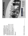
~YRA..N\.\d
Oold )czricz)
MODEL:906VL
Built in FM Antenna Booster
10 Band Graphic Equalizer Booster
With Scanning and Night Illumination
For 12 Volts D.C. Negative Ground System Only
OPERATING INSTRUCTIONS:
6
n
IDi
~
5
1.
FIG.1
POWER SWITCH:
Press to switch amplifier on.
2.
FM ANTENNA BOOSTER SWITCH:
Press the switch to improve FM reception.
The switch works independently even when power switch off.
3.
HOLD SWITCH:
Press the switch to light up all the LED indicator built in the shaft of slide
equalizer control. (Scan/Level switch at "SCAN" position).
4.
SCAN/LEVEL SWITCH:
When switch set at "SCAN" position, the LEOs built in each slide control scan
automatically from left to right over each frequency points. (Hold switch at
"OFF" position) when switch set at "LEVEL" position, the LEOs built in each
slide control give visual indication of output power radiating from midpoint of
frequencies.
5.
ACRYLIC COVER:
Remove the acrylic cover for adjustment of slide control
6.
EQUALIZER CONTROLS:
10 band frequency control, slide the knobs up to boost the signal, slide down to
attenuate. The signal is unaffected at center position.
2
7.
FADER CONTROL:
A) For 4 speakers system:
Fader control can be adjusted by turning the knob to the front side brings
up the level of the front speakers, turning it to the rear side brings up that
of the rear's and tuning it at mid-position both sets of speakers are at
maximum level.
B)
For 2 speakers system:
The Fader control knob should be turned to the center of position which
provides the loudest sound for using set of speakers.
INSTALLATION:
r;/..
3
ELECTRICAL CONNECTIONS:
for 4 Speaker System (4 or 8 ohm)
R.F.
OUTPUT (TO
ANT
INPUT
RADIO)
~--1
---------",
r-------------,
IFOR
CAR
,
,,
,
,
,,
,
,
LOW IMP, AUD10 I
IINPUT \( Hl
L
\
LEVER)
I
RED
~
+El
rr-"--;:~--=-:::l--,
(+)
II:
:
GREEN
I
GREEN J WHlTE
~=~----ll
RI GHT
+B
OUTPUT
(-)
I
II
(INPUT)
Urr
L
GRAYIWHlT£
,-------,
G-=:O
REAR LEFT
SPEA KER
REAR RIGHT
SPEAKER
COMMON GROUND
RADlOI PLAYER
SYSTEM
I OUTPUT
I l
R
I
I
I
I
I
I
I
I
,0
I
I
,
,
I
I ~
1----------,
II
R
INPUT
(INPUT)
~
"
•
I 4
10.:_
I
I
:
'>
I
II
I
I
I
~~
[r W
,~...J
1:r:3=
w
a
~~
I >--
I
I
I
L
FRONT R1GHT
SPEAKER
,
It->o-
I«:::l
:~~
FRONT LEFT
SPEAKER
I
:
--J
for 2 Speaker System (4 ohm)
A.F.
OUTPUT (TO
ANT
CAR
INPUT
RADIO)
~--1
--------,,
,
,,
r~------------,
[FOR
LOW IMP. AUD10 I
U!::!~~_~~~_L~::~~.~J
\
RED
I
+B--j11t=I------"=--.J
,,
I
rr-"---~-::~l- - l
(+)
II
I
I
I
GREEN
RIGHT
OUTPUT ( - )
.=.:.~--l'
I
II
I
(INPUT)
GREEN I WHITE
GRAVIWHlTE
'tTB
OND
L
'-OUTPUTI
+ B c,-:;O
I
LEFT
r------------:
i Sy~~~~ONRAGD~~~Np~AYER !
SPEAKER
,
INPUT
(lNPUT)
RIGHT
SPEAKER
L
R
I
I
:
I
I
I
I~
I
I ~
11i~
:
I D
I
I
~~
I
~ lj
:
1:I::3C
I
I ~:;
1>- _
:
I
:
I
:
>
I:~
I~::
L
5
I
I
I
I
i
:
..J
SPECI FICATlONS:
Power Supply
12
.
volt
Nominal,
D.C.
Negative
Ground
Output Power
150 Watt x 2 Max.
.
Speaker Impedance. . . . . . . . .
4 ohm (4 ohm - 8 ohm allowable)
Frequency Response. . . . . . . .
20 Hz - 20 KHz ± 1dB
Signal to Noise Ratio. . . . . . . . . . . ..
more than 60dB
Input Impedance
High Input 47 kn
Low Input 100 n
Control Frequency . . . . . . . . . . . . ..
30Hz,
60Hz,
1KHz,
2KHz,
Control Range. . . . . . . . . . . . . . . ..
± 10dB
Fuse
8A
"
120Hz, 250Hz, 500Hz,
4KHz,
8KHz,
FM Ant Max. Sensitivity
5 dB
Dimensions (W x H x D)
176 (W) x40 (H) x 154 (D) mm
16KHz
CAUTION:
1.
The unit and the speaker will be damaged if there is a connet::tion to the ground
(chassis) from any speaker wire.
2.
For best result, speakers should be rated to safely handle the additional power
output provided by the unit speakers with low power rating may be damaged.
3.
This equipment is intended for use in 12V DC negative ground electrical system
only. The use of voltage or polarity converters is discouraged.
4.
To avoid the possibility of short-circuiting the output stages both radio and the
amplifier should be switched-off (preferably disconnected from the power
supply) when installing and wiring the speakers.
5.
Use high or low level inputs to the equalizer. Both can-not be connected at the
same time.
B
CARE AND MAINTENANCE
Keep
the
equalizer/
booster away from dust
and dirt, which can
cause premature wear
of parts.
Your Pyramid 300 Watt Stereo 10-Band
Equalizer/Booster is an example of
superior design and craftsmanship.
The following suggestions will help you
care for your equalizer/booster so you
can enjoy it for years.
@
)\
,I "',"
Keep
the
equalizer/
booster dry, If it does
get wet, wipe it dry immediately. Liquids contain minerals that can
corrode electronic circuits.
'
(:j
I
I
./
'- I"
'
. .
Use and store the equalizer/booster only in normal temperature environments. Temperature
extremes can shorten
the life of electronic devices and distort or melt
plastic parts.
Handle the equalizer/
booster gently and carefully. Dropping it can
damage
the
circuit
boards and can cause it
to work improperly.
7
Wipe
the
equalizer/
booster with a damp
cloth occasionally to
keep it looking new. Do
not use harsh chemicals, cleaning solvents,
or strong detergents to
clean
the
equalizer/
booster.
www.pyramidcaraudio.com