1
oPYLE
= PRO
24 CONTROLS 12-BAND
STEREO GRAPHIC EQUALIZER
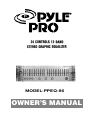
MODEL:PPEQ-86
OWNER’S MANUAL
INTRODUCTION
PPEQ-86 narrow band frequency balance controls provide an infinite frequency response
variations to allow you matching your speakers to your room, reducing or eliminating
inadequacies in your high fidelity music system, tailoring the reproduction of music in
accordance to your choice.
PPEQ-86 can enhance your sound system in the following ways:
Any system suffering from rumble or low frequency overload can be remendied by
attenauting the lowermost controls of the equalizer. With little in the way of fundamentals
below 30Hz, it is unlikely you will miss any of the music.
Noises due to the scratches on the record surface or even the hiss on the tape can be
eleminated or reduced by bringing down the control level at 9 KHz. Even Dolby processed
tape or encoded FM Broadcasts can be compensated for the boosted highs.
Tonal quality of Broadcasting Stations that attenuate or accentuate either highs or lows
can be equalized for pleasant listening. High performance recording tapes that require
special equalization in playback can be accomodated by appropriate adjustments on the
controls of PPEQ-86.
Phono cartridge or speaker inadequacies can be corrected for pleasant listening. Find the
correct slide control on your PPEQ-86 and move it up or down a few dB.
In cases, when you want to hear the vocalist or any specified musical sound, louder, the
PPEQ-86 can give you perfect satisfaction.
INSTALLATION
CAUTIONS:
(1) The unit should connect to an AC out-let providing the proper voltage of 120 V,220 V
AC/60Hz,50Hz.
(2) If your sound system does not provide a tape monitor function, it will not be possible
to connect the equalizer with your sound system.
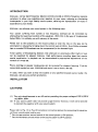
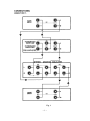
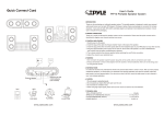
Please refer to Fig. (1) or Fig. (2) installation instruction picture for connecting the equalizer
with your sound system and be sure.
* Set the tape monitor control switch of the sound system to ON position.
* Set the loundness control switch of the sound system to OFF position.
—2—
CONNECTIONS:
CONDITION 1.
TAPE
DECK
©
LINE
—NPUT-— | OUTPUT
©
Ty
N
A
L
IAE ——
INTEGRATED
RECEIVER O
INTEGRATED REC! REC 2
AMPLIFIER
enviar O O |
o
MONITOR
|
Vv
— |
STEREO GRAPHIC
|e
EQUALIZER
LINE
| — IN ——— 2
©
©
TAPE
OUT
29
29
OUT IN
e
TAPE
DECK
0:0
INPUT —— LINE
——— 1 OUTPUT
Ÿ
ma
©
Fig. 1
- CONDITION 2.
AM/FM STEREO TUNER
©
У
L
GND
© OUTPUT
7) ©-
INTEGRATED
RECEIVER O- L
y
INTEGRATED
ML iFien TAPE REC MONITOR
A
PRE- AMPLIFI
У
—
A
STERED GRAPHIC | EQUALIZER
Z— + — LINE ——— —— TAPE —
- © © ©- |
@- © ©
1——IN— 2 OUT OUT IN
DECK | |
INPUT —— LINE —— OUTPUT — |
©
Fig. 2
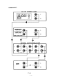
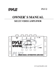
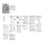
OPERATING:
= pce ym Le В,
РЕ rs
= ee
44
0000
4 5 6 7
e VOLTAGE ® e
090 06
1] 000 09€
- |
—
©
—
©
—
>|
—
O1
—
an
—
WT
—
N
—
A — |
Fig.3
1. POWER SWITCH
To push in the power switch for power supplied from house-hold AC outlet to operate
the equalizer and that time the LED indicator should be lighted. Contrary, to push out the
power switch for shutting off power supply when the equalizer does not work and that
time the LED indicator should not be lighted.
2. FREQUENCY BOOST-CUT CONTROLS
Control over the response curve is accomplished by 12 slide control levels each of left
and right channel. (a total of 24 slide control levels) which permit a boost or cut of 12
dB minimum at the frequencies of 15Hz, 30Hz, 60Hz, 120Hz, 240Hz, 500Hz, 1KHz,
2KHz, 4KHz, 8KHz, 16KHz, 32KHz.
3. BLUE LED LEVEL DISPLAY METER
4. EQ IN/OUT SWITCH
When depressed, EQ effect is on.
5. SOURCE/TAPE SWITCH
Chooses input of source 1, 2, or tape from the rear panel connectors.
6. LINE 1/LINE 2 SWITCH
Chooses one of two sources plugged into the rear panel connectors.
7. PRE/POST SWITCH
Determines whether the output signal comes from before or after‘the equalizer circuits,
but does not affect the tape circuits.
_5_
10.
11
12.
13.
14.
15.
16.
17.
. LEVEL CONTROLS
Located on the front panel of your Equalizer are two Variable Frequency Spectrum
Level Balancing Controls. |
Since it is possible that certain settings of the Frequency Equalization Slide Controls
will increase or decrease the total average signal level, the LEVEL CONTROLS are
used to adjust each channel so that the average output will be equal to the input sign-
al level. This adjusts the Equalizer for Unity Gain,
. LED METER ADJUSTMENT
When rotated, this control vary the sensitivity of the LED Meter. It should be adjust-
ed so that the loudest and softest sound will be indicated in right position.
POWER CORD CONNECTOR
This connector is meant for the connection of the supplied main cord.
. TAPE IN JACKS
For playback of tape, allowing EQ of pre-recorded tapes or re-EQ of a tape made
using EQ.
TAPE OUT JACKS
These outputs feed your tape deck, enabling EQ of recordings being made.
LINE OUTPUT JACKS
These outputs typically plug into your preamp’s ‘tape monitor’’ jacks.
LINE 2 SOURCE INPUT JACKS
LINE 1 SOURCE INPUT JACKS
110V 60Hz/220V 50Hz SELECTOR
GROUND LIFT SWITCH
This switch is used to disconnect the signal ground from the mains and chassis earth
ground. If it is determined that the equalizer is the cause of hum or buzz in your system
due to a ground loop, move this switch to the "lift" position.
In this way, the equalizer is used to flatten the often uneven frequency response of stereo
‘components and compensate for peculiarities in room acoustics and also to reduce noise
in program source.
By moving the appropriate controls up or down a few dB, you can alter the total quality
to suit your personal preference.
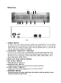
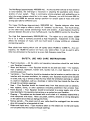
TYPICAL FREQUENCY RESPONSE PER CHANNEL
(dB)
+12
+8
+4
—4
- 8
—12
O
2 345 7100 2 345 7 IK 2 345 710 2 3 45 7I00K
FREQUENCY Hz Fig. 4
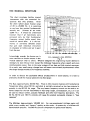
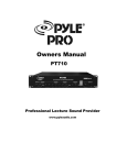
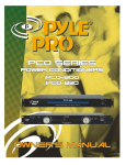
THE MUSICAL SPECTRUM
[7] == Approximate fundamental range (and lower harmonies)
This chart correlates familiar musical Lon == Approximate range of relatively important harmonics {subjective by necessity)
instruments with the numerical fre- о
quencies that they produce. Given LJ
the often talked about musical range Drome = de
of 20 to 20,000 Hz, it is surprising LL ттт
to see how low musical fundamentals — == I
actually are. (Almost all are under Ew li
3,500 Hz.) It should be understood == zz A)
however that if all instruments were 2227
perceived only by their fundamental — > |
frequency output (white areas), they == La
would all sound alike. It is the har- | da — =a
monics or overtones (Shaded areas) a 3
that give each individual instrument - EL T
Its character or timbre and set it apart ay
from the rest. Fo Td
20 [3040 [20] [129] [280] [4096] [8905] [16009] Hz
Interestingly enough, the human ear 5 [= FREQUENCY LEVEL CONTROLS
more sensitive to certain octaves in the Fig. 5
musical spectrum than to others. Whoever designed this engineering marvel deemed it
necessary to tune the ear more toward the midrange frequencies where speech and voice
communication occur, than to the outer octaves of low bass and high musical overtones.
As a result, very small energy changes here will cause a more drastic psychoacoustic effect
that larger changes would at the frequency extremes,
In order to discuss the qualitative effects of adjustment in tonal balance, it is best to
arbitrarily divide the musical spectrum into five ranges:
The Bass {approximately 20-140 Hz). There is little musical material with fundamental
frequencies below about 60 Hz, and what is normally perceived as low bass material is
actually in the 60-140 Hz range. The very lowest frequency control can be used to en-
hance output for the few instruments in that range (organ, contrabassoon, etc.) or it can
be used to reduce rumble, acoustic feedback and other low frequency aberrations. The
30 Hz, 60 Hz and 120 Hz controls will cause the greatest percepable changes in ‘‘bass
response”
The Mid-Bass (approximately 140-400 Hz). An over-accentuated mid-bass region wil!
yield a very muddy and “boomy” quality to the music. A system shy of mid-bass will
sound hollow and thin. The 240 Hz control is important for good overall balance.
—7—
The Mid-Range (approximately 400-2600 Hz). As the area where the ear is most sensitive
to tonal balance, the mid-range is important in adjusting the qualitative sonic charac-
teristics of your system. There is controversy among engineers and audiophiles as to
what the proper balance should be in this range. Moreover, you will find some 500 Hz,
1000 Hz and 2000 Hz controls settings optimum for certain types of music with other
settings just right for different types.
The Upper Mid-Range (approximately 2600-5200 Hz). Speaker designers often boost
output in this range to effect a quality of “presence” to the music, Too much energy,
on the other hand, sounds overbearingly harsh and strident. A good balance should be
achieved between this and a more muffled sound. Use the 4000 Hz control for this effect.
The High End (approximately 5200-20,000 Hz). The region up to only about 12,000
Hz or so is what is normally perceived as high frequencies. Adjustment in this range
affects the brilliance of music, with too much boost in energy yielding on unpleasant
and piercing quality.
Most adults have hearing which rolls off rapidly above 14,000 to 17,000 Hz. As a con-
sequence, the 16,000 Hz control will have a very subtle effect. It can be used to add a
little more dimension to the sound or as a very high frequency noise filter.
SAFETY; USE AND CARE INSTRUCTIONS
Read Instructions — All the safety and operating instructions should be read before
your Equalizer is operated.
Water and Moisture — Your Equalizer should not be used near water — For example,
near a bathtub, washbowl, kitchen sink, laundry tub, in a wet basement, or near a
swimming pool, etc. |
Ventilation — Your Equalizer should be situated so that its location or position does not
interfere with its prope ventilation, for example, your Equalizer should not be situated
on a bed, sofa, rug, or similar surface that may block the ventilation openings; or, placed
in a built-in installation, such as a bookcase or cabinet that may impede the flow of air
through the ventilation openings: |
Heat — Your Equalizer should be situated away from heat sources such as radiators,
heat registers, stoves, or other appliances (including amplifiers) that produce heat.
Power .Sources — Your Equalizer should bé connected to a power supply only of the
type described in the operating instructions or as marked on your Equalizer.
Cleaning — The cabinet can be cleaned with a soft cloth or if necessary cleaned with a
cloth dampened with water. Never use polish, solvents, abrasives or strong detergents
on the cabinet since these can damage the finish.
Nonuse periods — The power cord of your radio should be unplugged from the outlet
when left unused for a long period of time. |
Object and liquid entry — Care should be taken so that objects do not fall and liquids
are not spilled into the enclosure through openings.
—8—
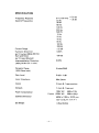
SPECIFICATION
Frequency Response 5 Hz-100 KHz o da
Control Frequencies 15 Hz
30 Hz
60 Hz
120 Hz
240 Hz
500 Hz
1KHz
2KHz
4KHz
8KHz
16KHz
32KHz
Control Range +12 dB
Harmonic Distortion 0.02%
(at 1V output 20Hz-20KHz)
Hum and Noise —90 dB
(at 1V input Shorted)
Intermodulation Distortion 0,02%
(70Hz/7KHz @ 4:1 ratio)
Dynamic Range 8 volts/RMS
{10K Ohms load)
Gain Level 0 dB + 1 dB
Input Impedance 50K Ohms
Inputs 2 main & 1 tape monitor
Outputs 1 main & 1 tape out
Power Consumption 120V AC /60Hz 11W
| Export (220V AC /50Hz 15W)
Cabinet Dimension 482W x 132H x 187D mm
(19) x (5.2) x (7.4)
Set Weight 4.5kg (9.91bs)
CARE AND MAINTENANCE
Your Pyle Stereo 12-Band Graphic/
Equalizer is an example of superior
design and craftsmanship. The following
suggestions will help you care for your
equalizer/booster so you can enjoy
it for years.
Keep the graphic/
equalizer dry. If it does
get wet, wipe it dry im-
mediately. Liquids con-
tain minerals that can
corrode electronic
circuits.
oO Use and store the
graphic/equalizer only in
NY normal temperature en-
Cr vironments. Tempera-
ture extremes can
shorten the life of elec-
tronic devices and distort
or melt plastic parts.
Handle the graphic/
equalizer gently and
carefully. Dropping it can
damage the circuit
- boards and can cause it
to work improperly.
— 10 —
Keep the graphic/equa-
lizer away from dust and
dirt, which can cause
premature wear of parts.
Wipe the graphic/equa-
lizer with a damp cloth
occasionally to keep it
looking new. Do not use
harsh chemicals, clean-
ing solvents, or strong
detergents to clean the
graphic/equalizer.
NOTES
— 11 —
www.pyleaudio.com