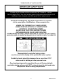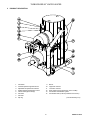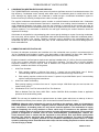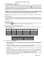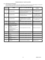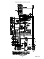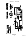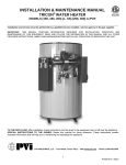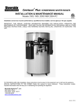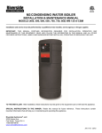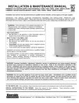
1
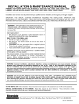
INSTALLATION & MAINTENANCE MANUAL TURBOPOWER® 99 GAS WATER HEATER MODELS: (742, 1485, 2228, 2971) N, P, L, SS (330, 425, 600, 950, 1200) A-TP Installation and service must be performed by a qualified service installer, service agency or the gas supplier. IMPORTANT: THIS MANUAL CONTAINS INFORMATION REQUIRED FOR INSTALLATION, OPERATION AND MAINTENANCE OF THIS EQUIPMENT. READ AND FOLLOW THE INFORMATION IN THIS MANUAL AND ALL OTHER PROVIDED INSTRUCTIONS, LABELS AND MARKINGS BEFORE INSTALLING, OPERATING OR SERVICING THIS UNIT. TO THE INSTALLER: After installation, these instructions must be given to the equipment user or left near the appliance. SPECIAL INSTRUCTIONS TO THE OWNER: Retain this manual for future reference. These instructions contain important information that will help you in maintaining and operating this appliance. PVI INDUSTRIES, LLC - Fort Worth, Texas 76111 - www.pvi.com - Phone 1-800-433-5654 1 PV500-12 08/12 TURBOPOWER 99 WATER HEATER TABLE OF CONTENTS 1. 2. 3. 4. 5. 6. 7. 8. 9. 10. 11. 12. 13. 14. 15. Safety Considerations Product Descriptions Standard Features and Equipment 3.1 Warranty Water Heater Installation 4.1 Checking Equipment Before You Install 4.2 Codes 4.3 Electrical Requirements 4.4 Location 4.5 Installation 4.6 Service Clearances 4.7 Clearances to Combustible Surfaces Condensate Neutralization & Disposal Combustion and Ventilation Air Vertical and Horizontal Remote Air 7.1 Vertical or Horizontal Remote Air Option 7.2 Remote Air Piping Design 7.3 Maximum Allowed Combustion Air Vent Length (Equivalent Length) 7.4 Remote Air Piping of Multiple Units Venting Products of Combustion 8.1 Vent System Design 8.2 Venting of Multiple Units 8.3 Maximum Allowed Vent Length (Equivalent Length) 8.4 Vent Construction and Assembly 8.5 Horizontal and Vertical Venting Through a Wall or Roof Gas Supply and Piping 9.1 Inlet Pressure 9.2 Manifold Pressure 9.3 Gas Piping Size 9.4 Appliance Isolation during Gas Supply Piping Pressure Test 9.5 Gas Connection 9.6 Gas Train and Controls Certification 9.7 Gas Control Trains General Information 10.1 Temperature and Pressure Relief Valve(s) 10.2 Upper LED Readout 10.3 High Water Temperature Limit Control 10.4 Cathodic Protection 10.5 Thermal Expansion TempTrac Electronic Controller Panel 11.1 Principle of Operation 11.2 Lower LED Readout 11.3 Upper LED Readout 11.4 Control Buttons 11.5 To View the Setpoint 11.6 To Change the Setpoint 11.7 To Change Other Parameters 11.8 LED Display Alarm Messages Remote Connections – Terminal Strip Start-up Procedure Periodic Maintenance Diagrams Warranty forms ship separately with each product. 2 PV500-12 08/12 TURBOPOWER 99 WATER HEATER 1 SAFETY CONSIDERATIONS WARNING: If the information in the supplied manual(s) is not followed exactly, a fire, explosion or exposure to hazardous materials may result, causing property damage, personal injury or loss of life. FOR YOUR SAFETY Do not store or use gasoline or other flammable vapors or liquids in the vicinity of this or any other appliance. WHAT TO DO IF YOU SMELL GAS Do not try to light any appliance. Do not touch any electric switch; do not use any phone in your building. Immediately call your gas supplier from a location away from your building and the smell of gas. Follow the gas supplier's instructions. If you cannot reach your gas supplier, call the fire department. Installation and service must be performed by a qualified installer, service agency or the gas supplier. This product contains, or may come to contain materials that have been identified as carcinogenic, or possibly carcinogenic to humans. Before installing, servicing or removing this product, read and follow the supplied instructions WARNING: Installation and service must be performed by a qualified installer, service agency or the gas supplier, who must read and follow the supplied instructions before installing, servicing or removing this appliance. Refer to the information contained in this manual. Improper installation, adjustment, alteration, service or maintenance can cause property damage, personal injury, exposure to hazardous materials or loss of life. WARNING: Do not use this appliance if any part has been under water. Immediately call a qualified service technician to inspect the unit and to replace any part of the control system, all gas controls and all other items affecting safe appliance operation and which has been under water. WARNING: In an emergency shut the main gas supply valve to the appliance from a location safely away from the emergency. Failure to follow these instructions can cause property damage, personal injury, and exposure to hazardous materials or loss of life. PRODUCT SAFETY INFORMATION REFRACTORY CERAMIC FIBER PRODUCT WITH CRYSTALLINE SILICA WARNING: This product contains or may come to contain crystalline silica, which has been identified by the International Agency for Research on Cancer (IARC) as carcinogenic to humans. This product also contains refractory ceramic fibers, which have been identified by the IARC as possibly carcinogenic to humans. Avoid breathing fiber particulates and dust. RISKS: Air borne fibrous insulation is a possible cancer hazard by inhalation. Airborne crystalline silica may cause silicosis (lung disease) by inhalation. May cause temporary irritation to eyes, skin, and respiratory tract. PRECAUTIONARY MEASURES: Minimize airborne fibers with engineering controls. Use NIOSH/MSHA approved respirators as required (see MSDS). Wear long sleeved, loose-fitting clothing, eye protection and gloves. FIRST AID MEASURES: (If any of the irritations listed persists, seek medical attention) Eyes: Flush with water. Skin: Wash with soap and warm water. Ingestion: Do not induce vomiting. Get medical attention if gastrointestinal symptoms develop. Inhalation: Remove to fresh clean air. WARNING: If you are unfamiliar with the safe handling of refractory ceramic fiber products, or if you wish additional information prior to beginning any disassembly of the water heater or boiler that might expose refractory ceramic fiber materials, contact: Unifrax Corporation, 2351 Whirlpool Street, Niagara Falls, NY 14305-2413, 1-800-322-2293. IDENTIFICATION OF REFRACTORY CERAMIC FIBER MATERIALS (RCF): The burner, lower tank and upper and lower flue collector assemblies utilize RCF material. (The RFC materials are located within the product and not generally exposed except during service, disassembly or assembly.) 3 PV500-12 08/12 TURBOPOWER 99 WATER HEATER IMPORTANT SAFETY NOTE It takes only 5 seconds of skin contact with 140°F water to cause a second degree burn! You must protect against high water temperatures at all lavatories, tubs, showers and other points of hot water contact. Accidental scalding from high water temperatures is a greater risk in some types of installations. Some examples are: HOMES FOR THE MENTALLY HANDICAPPED HOMES FOR THE PHYSICALLY HANDICAPPED HOSPITALS AND NURSING HOMES ELDER CARE FACILITIES AND REST HOMES ORPHANAGES AND CHILD CARE FACILITIES OTHER INSTALLATIONS - WHERE RESPONSE TO CONTACT WITH HOT WATER MAY BE SLOWER OR WHERE THE DANGER OF HOT WATER CONTACT IS GREATER Thermostatically controlled mixing valves must be used in the design of the potable hot water system. Potable hot water should be tempered to no more than 110°F when used for bathing or other personal uses. Good engineering practice mandates the use of thermostatically controlled mixing valves set at 120°F or less to keep the delivered water temperature below scalding temperatures. 4 PV500-12 08/12 TURBOPOWER 99 WATER HEATER 2 PRODUCT DESCRIPTION 1. 2. 3. 4. 5. 6. 7. 8. Flue stack * Fixed temperature high limit device Adjustable temperature limit device Digital operating temperature control Control switch(s) and fuse(s) Gas valve Gas inlet Drip leg 9. 10. 11. 12. 13. 14. Burner Upper flue collector Lower flue collector Rear module access (optional on some models) Condensate neutralization system Condensate drain (must be plumbed to floor drain) * (* Not furnished by PVI) 5 PV500-12 08/12 TURBOPOWER 99 WATER HEATER 3 STANDARD FEATURES AND EQUIPMENT 3.1 Warranty Factory warranty does not cover improper installation or operation. (See warranty for complete details). Warranty exclusions include but are not limited to failure or malfunctions resulting from: 1. 2. 3. 4. 4 Failures to properly apply, install, operate, or maintain the appliance in accordance to printed instructions. Abuse, alteration, accident, fire, flood and the like. Sediment or lime buildup, freezing or any other conditions causing inadequate circulation. Corrosive or contaminated atmosphere. WATER HEATER INSTALLATION 4.1 Checking Equipment Before You Install Inspect the unit completely upon receipt from the freight carrier before signing the bill of lading. Inspect the appliance and all accompanying parts for signs of impact or mishandling. Verify the total number of pieces shown on packing slips with those actually received. Contact the freight carrier immediately if any damage or shortage is detected. 4.2 Codes The equipment shall be installed in accordance with those installation regulations in force in the local area where the installation is to be made. These shall be carefully followed in all cases. Authorities having jurisdiction shall be consulted before installation is made. In the absence of such requirements, the installation shall conform to the latest edition of the National Fuel Gas Code, ANSI Z223.1. Where required by the authority having jurisdiction, the installation must conform to American Society of Mechanical Engineers Safety Code for Controls and Safety Devices for Automatically Fired Boilers, No. (CSD-1). All appliances conform to the applicable sections of the latest edition of ASME Boiler and Pressure Vessel Code, Section IV. Where required by the Canadian authority having jurisdiction, the installation must comply with CAN/CSA B149 and/or B149.2 and/or provincial regulations. 4.3 Electrical Requirements WARNING: Turn off all electrical service to the appliance when accessing the controls located inside the control cabinet. The cabinet contains high voltage wiring and terminals. If the electrical service is not turned off and these wires or terminals are touched, a dangerous shock causing personal injury or loss of life could occur. Close the control cabinet before restoring electrical service to the appliance. See product specification sheets and/or appliance labeling for branch service requirements. The appliance, when installed, must be electrically grounded in accordance with the requirements of the authority having jurisdiction or in the absence of such requirements, with the latest edition of the National Electrical Code ANSI/NFPA No. 70. When the unit is installed in Canada, it must conform to the CSA C22.1, Canadian Electrical Code, Part 1 and/or Local Electrical Codes. 1. All wiring between the unit and field installed devices must be made with type T wire. 2. Line voltage wire exterior to the appliance must be enclosed in approved conduit or approved metal clad cable. 3. To avoid serious damage, DO NOT energize the unit until the system and appliance is full of water. 4.4 Location These units are suitable for indoor installation only. 1. Locate the unit so that if water connections should leak, water damage will not occur. When such locations are unavoidable, install a suitable drain pan, and plumb pan to ensure adequate drainage in the event of a leak. Under no circumstances is the manufacturer responsible for water damage in connection with this unit, or any of its components. The manufacturer’s warranty does not cover water damage. 2. Protect associated electrical components and electrical connections from water (dripping, spraying, rain, etc.) during appliance operation and service. 6 PV500-12 08/12 TURBOPOWER 99 WATER HEATER 3. Place the appliance on a level, non-combustible floor. Concrete over wood is not considered noncombustible. 4. Do not install on carpet or other combustible floor coverings. 5. Installation over a combustible floor: Units installed over a combustible floor MUST be provided with a base of hollow clay tile or concrete blocks from 8" to 12" thick and extending 24" beyond the sides. Place the blocks in line so that the holes line up horizontally to provide a clear passage through the blocks. Install 1/2” fireproof millboard with a 20-gage sheet metal cover over the block base. Center the unit on the base. Also follow this procedure if electrical conduit runs through the floor, and beneath the appliance. A field-installed base must meet all local fire and safety code requirements. 4.5 Installation WARNING: Use industry standard safe rigging methods when attempting to lift or move this product. Failure to follow these instructions could result in property damage, serious injury or death. One common method includes the use of straps and spreader bars, lifting from the water heater base skid assembly. 1. Check the data decal on the appliance. Be sure the electrical, water, oil, or gas supply is adequate for the installation. 2. Carefully remove all shipping supports and bracing. 3. Use only non-ferrous water piping and fittings. Do not use galvanized pipe or fittings. Use of ferrous or galvanized pipe or fittings can cause rust to form. 4. Install shut-off valves and unions on the inlet and outlet water piping for servicing. Use caution when threading pipe nipples into tank connections to prevent cross threading, or over-tightening. Always use a back-up wrench on tank nipples when tightening unions, valves, etc. 5. Insulate hot water and return circulation lines. Insulate cold water supply lines if subject to freezing during shutdown periods. IMPORTANT: Do not use the plumbing connected to the appliance as a ground for welding or any other purpose. 6. Pipe the drain valve to a suitable open drain. 4.6 Service Clearances Allow sufficient space to provide adequate clearances on all sides for service and inspection. Recommended clearance is 24” at the top and front, 18” at left and right sides of the appliance. Optional equipment may increase the clearance requirements. Allow sufficient space for installing and servicing connections such as water, gas, vent, combustion air, electrical, pump and other auxiliary equipment. 4.7 Clearances to Combustible Surfaces The appliance must not be installed on a combustible floor, on carpet, on other combustible floor coverings or on a non-combustible floor covering combustible material. The minimum clearance to unprotected combustible material is 6” from the front, top, left and right sides of the burner and flue collector. Combustible materials are allowed to contact the tank sides and top, however service clearances are recommended. 7 PV500-12 08/12 TURBOPOWER 99 WATER HEATER 5 CONDENSATION NEUTRALIZATION AND DISPOSAL The TURBOPOWER® 99 condensing water heater will produce significant amounts of condensate because of its high efficiency. Condensate occurs naturally when water vapor in combustion gases is cooled below the dew point. Although only slightly acidic, the condensate is routed through a condensate neutralization system to become lower the pH, allowing for disposal into a drain or sewer system. The supplied condensate neutralization system contains a crushed limestone neutralization bath. Condensate slowly flows through a crushed limestone bed and is neutralized, thus avoiding chemical treatment or dilution using substantial quantities of tap water. Over time the limestone is consumed by this process and must be replaced. Periodically test the condensate with a pH meter or pH paper and if lower than 5, the crushed limestone must be replaced. If no condensate is observed, the main pipe containing the crushed limestone should be inspected for blockage. If the heater is not installed on a housekeeping pad to ensure gravity drainage, a means of removing condensate, such as a pump, will be required. The neutralization bath and condensate trap are filled with condensate (water), even when the heater is not running. Therefore, protection must be provided to the neutralization bath, the condensate trap and to the condensate drain path, so that condensate does not freeze and damage parts or block condensate flow. 6 COMBUSTION AND VENTILATION AIR Provisions for adequate combustion and ventilation air to the mechanical room must be in accordance with the “Air for Combustion and Ventilation” section in the latest edition of the National Fuel Gas Code, ANSI Z223.1 and/or CAN/CSA B149, Installation Codes or applicable provisions of the local building codes. Equipment located in confined spaces requires two openings installed within 12” (300 m) from the top and bottom of the room to assure adequate combustion air and proper ventilation. The total input of all gas utilization equipment installed in the room must be used to determine the required minimum air volume needed for combustion, ventilation and dilution of flue gasses. 1. 2. All Air From Outdoors: a. Each opening requires a minimum free area of 1 square inch per 4000 Btu/hr input if directly communicating with the outdoors or communicating to the outdoors through vertical ducts. b. Each opening requires a minimum free area of 1 square inch per 2000 Btu/hr input if communicating with the outdoors through horizontal ducts. All Air From Inside The Building: Each opening requires a minimum free area of 1 square inch per 1000 Btu/hr input, but not less than 100 square inches (0.06 m2). 3. Combination Of Air From The Indoors And From The Outdoors: Refer to National Fuel Gas Code, ANSI Z223.1 and/or CAN/CSA B149, Installation Codes or applicable provisions of the local building codes. NOTE: This unit may be installed with an optional remote air intake system which uses a make-up air duct to draw combustion air directly from outdoors. (See Vertical and Horizontal Remote Air Section.) WARNING: Adequate clean combustion air must be provided to the appliance. Under no circumstances should the appliance ever be under a negative pressure. Particular care should be taken when exhaust fans, compressors, air handling units, etc. may rob air from the appliance. The combustion air supply must be completely free of any chemical or fumes, which may be corrosive to the appliance. Some common chemical fumes to avoid are fluorocarbons and other halogenated compounds, most commonly present as refrigerants or solvents, such as Freon, trichloroethylene, perchlorethylene, chlorine, etc. These chemicals, when in contact with the equipment or when burned, form acids which quickly attack the tubes, flue collector, stack and other appliance and auxiliary equipment. The result of inadequate clean combustion air or negative pressure can be premature unwarranted product failure or unsafe operation producing carbon monoxide that could escape into the building. Exposure to carbon monoxide can lead to injury or death. 8 PV500-12 08/12 TURBOPOWER 99 WATER HEATER 7 VERTICAL AND HORIZONTAL REMOTE AIR 7.1 Vertical or Horizontal Remote Air Option The vertical or horizontal remote air system requires a factory or site installed remote combustion air inlet option package. If your water heater does not include this optional equipment, contact your PVI sales representative to purchase the Remote Air Kit. The air inlet termination cap supplied with combustion air inlet option must be installed. Do not fabricate this from locally available parts as it may cause unsafe operation. Combustion air supplied from outdoors must be free of contaminants. 7.2 Remote Air Piping Design The water heater can obtain remote air either vertically, through a ceiling or roof, or horizontally through a wall. Locally obtained solid PVC pipe must be attached to the remote air inlet. Larger solid PVC pipe may be substituted; however a PVC increaser must be used. When the remote combustion air inlet and flue gas outlet are located on the same roof top surface, the cap must terminate at least 3 feet lower than the flue gas outlet, if located within a 10 foot radius. Locate the remote combustion air inlet and the flue gas vent outlet in a wall or roof with similar wind pressure. Install the inlet cap at least one foot above the rooftop or at least 18" above grade and at least one foot above normal snow levels. WARNING: Locate the termination of the combustion air inlet outdoors to minimize flue gas recirculation and to minimize the opportunity for products of combustion to enter the building. Recirculation of flue gas (products of combustion drawn from the flue gas outlet into the combustion air inlet) can cause operational problems, premature unwarranted product failure or unsafe operation producing carbon monoxide. Exposure to carbon monoxide can result in property damage, personal injury or death. 7.3 Maximum Allowed Combustion Air Vent Length (Equivalent Length) Water Heater Prefix 742 1485 2228 2971 Input, Btu/h 500,000 999,000 1,500,000 1,950,000 W/Remote Air Input, Btu/h 500,000 950,000 1,500,000 1,850,000 100 equivalent feet, vent diameter: 6” 6” 8” 8” 225 equivalent feet, vent diameter: 10” 10” 12” 12” VENT PIPE FITTINGS EQUIVALENT (in feet) 90º Elbow 14 feet 90º Long Radius Elbow 12 feet 45º Elbow 6 feet For maxim allowed remote air lengths (equivalent length) longer than those shown above, contact the factory. 7.4 Remote Air Piping of Multiple Units Each unit must have a dedicated remote combustion air duct. Combining multiple-unit combustion air ducts into a common duct or breeching is not allowed. 9 PV500-12 08/12 TURBOPOWER 99 WATER HEATER 8 VENTING PRODUCTS OF COMBUSTION The TURBOPOWER® 99 is designed for operation with a "positive pressure vent system" constructed of locally obtained 4” or 5" (or larger) schedule 40 or 80 solid PVC or CPVC pipe. Do not use PVC or CPVC pipe with cell/foam type construction (such as “CellCore”) or other non-solid PVC plastic pipe. Larger solid PVC pipe may be substituted; however, a PVC increaser to the larger size must be used. Do not insulate the plastic vent pipe. Stainless steel venting listed by a nationally recognized testing laboratory for category IV positive pressure gas appliance venting may be used instead of plastic pipe venting. WARNING: Do not vent this water heater into an existing or traditional gas vent or chimney or combine the vent with any other appliance. Such venting could result in failure of the venting system and/or exposure to carbon monoxide which can result in property damage, personal injury or death. CAUTION: DO NOT use ABS pipe in the venting system. ABS can emit toxic fumes in the event of a building fire. 8.1 Vent System Design These water heater can be vented either vertically, through a ceiling or roof, or horizontally through a wall in any direction except down. The vent must be installed and supported to slope downward toward the water heater vent connection with at least ¼ inch drop per linear foot of horizontal vent run, to allow proper drainage of condensation. 8.2 Venting of Multiple Units Multiple heaters must not be vented into a common duct or breeching. Each unit must be independently vented in accordance with the instructions for either horizontal or vertical venting included above. 8.3 Maximum Allowed Vent Length (Equivalent Length) Maximum equivalent length of vent must not exceed the length identified in the table below (consult factory for longer equivalent lengths): Water Heater Prefix 742 1485 2228 2971 Input, Btu/h 500,000 999,000 1,500,000 1,950,000 W/Remote Air Input, Btu/h 500,000 950,000 1,500,000 1,850,000 100 equivalent feet, vent diameter: 4” 4” 5” 5” 225 equivalent feet, vent diameter: 6” 6” 8” 8” VENT PIPE FITTINGS EQUIVALENT (in feet) 90º Elbow 14 feet 90º Long Radius Elbow 12 feet 45º Elbow 6 feet 8.4 Vent Construction and Assembly 1. Clean and deburr all solid PVC, or solid CPVC pipe ends and the joint area and trial assemble (dry-fit) the vent before joining with PVC cement following the cement manufacturer’s instructions for making sound air and water tight joints. 2. If category IV stainless steel venting listed by a nationally recognized testing laboratory is used, follow the manufacturer’s instructions and assure all joints provide a water and gas tight assembly. 3. Vent support – The vent system should be supported at intervals no greater than four feet, to prevent sagging and distortion. 4. Testing for leaks. After the vent is assembled, close the end of the vent. With the gas supply turned off, energize the combustion blower to apply air pressure to the vent system. Spray each joint and vent connection with commercially available leak detection liquid to confirm no air is escaping from any point. Repair any leaks and retest. After testing is complete, REMOVE the temporary vent closure. 5. Attach the PVI vent termination cap supplied with the appliance. This termination is required for proper operation and no substitution is allowed. 10 PV500-12 08/12 TURBOPOWER 99 WATER HEATER 8.5 Horizontal and Vertical Venting Through a Wall or Roof Vent terminal locations, clearances, warnings and requirements stated in this manual apply, whether combustion air comes from the room or is ducted from outdoors. 1. The solid PVC or CPVC vent pipe must be sealed to the wall or roof at the point where it passes through the wall or roof. 2. The vent must be terminated with the vent termination cap provided by PVI. 3. The vent terminal must have a minimum clearance of 4 feet (1.22 m) horizontally from, and in no case be located above or below, electric meters, gas meters, regulators and relief equipment. 4. The vent cap shall terminate at least 3 feet (0.91 m) above any forced air inlet within 10 feet (3.05 m). 5. The vent shall terminate at least 4 feet (1.22 m) below, 4 feet (1.22 m) horizontally from or 1 foot (0.3 m) above any door, window or building air inlet to the building. 6. The vent system shall terminate at least 1 foot (0.3 m) above grade and at least 1 foot (0.3m) above possible snow accumulation levels and shall terminate at least 7 feet (2.13 m) above grade when located adjacent to public walkways or gathering areas. 7. To avoid a blocked flue condition, keep the vent cap clear of snow, ice, leaves, debris, etc. 8. The vent must not exit over a public walkway, near soffit vents or crawl space vents or other areas where condensate or vapor could create a nuisance or hazard or cause property or could be detrimental to the operation of regulators, relief valves or other equipment. 9. A horizontal vent must extend at least one foot beyond the wall. 10. A horizontal vent terminal must not be installed closer than 3 feet (0.91m) from an inside corner of an Lshaped structure. 11. A vertical vent should exhaust outside the building at least 2 feet (0.61 m) above the highest point of the roof within a 10-foot (3.05 m) radius of the termination. 12. The vertical termination must be a minimum of 3 feet (0.91 m) above the point of exit. A vertical termination less than 10 feet (0.91 m) from a parapet wall must be a minimum of 2 feet (0.61 m) higher than the parapet wall. 13. Follow all requirements in the “Venting” sections of this manual and other instructions and markings for venting flue products to the outdoors, obtaining adequate combustion and ventilation air and general installation instructions. 11 PV500-12 08/12 TURBOPOWER 99 WATER HEATER Horizontal Venting and Outside Combustion Air Follow all requirements in this manual and other instructions and markings for venting flue products to the outdoors, obtaining adequate combustion and ventilation air and general installation instructions. Vertical Venting and Outside Combustion Air Follow all requirements in this manual and other instructions and markings for venting flue products to the outdoors, obtaining adequate combustion and ventilation air and general installation instructions. 12 PV500-12 08/12 TURBOPOWER 99 WATER HEATER 9 GAS SUPPLY AND PIPING Verify that the type of gas specified on rating plate is supplied to the unit. This unit is orificed for operation up to 2000 feet altitude. The appliance Btu/h output, like other similar equipment, derates approximately 4% per 1000 feet above sea level. Consult Factory for installations above 2000 feet elevation. 9.1 Inlet Pressure: Measured at the inlet pressure tap located at the main gas cock. The inlet pressure must remain within the minimum flow pressure and maximum static pressure charted below while the unit is at rest and while the unit is operating at maximum firing rate. Water Heater Prefix 742 1485 2228 2971 Min Inlet Flow Pressure (in. W.C.) 5.0" Nat. Gas 5.5" Nat. Gas 6.0" Nat. Gas 11.0" Nat. Gas Max Static Pressure (in. W.C.) 14" Nat. Gas 14" Nat. Gas 14" Nat. Gas 14" Nat. Gas 9.2 Manifold Pressure: Measure at the pressure tap on the downstream side of the final manual shutoff valve for each stage of operation. The rated manifold pressure appears on the data label. The manifold pressure is preset at the factory and adjustment is not usually required. If adjustment is required, the burner must be firing at the minimum and/or full rate while the manifold pressure is adjusted. 9.3 Gas Piping Size: Use the values in “Convert Fittings To Equivalent Straight Pipe” to add the equivalent straight pipe for each elbow or tee to obtain the total distance from the meter. Use this corrected total distance from the meter for determining the suggested pipe size in the “Single Unit Installation Suggested Gas Pipe Size” table. CONVERT FITTINGS TO EQUIVALENT STRAIGHT PIPE Fitting Size (inches) ¾" 1" 1¼" 1½" 2" 3" Equivalent Length of Straight Pipe (feet) 2' 2' 5' 10' 14' 20' Equivalent Feet From Meter 25 40 60 80 100 125 150 175 200 3' 4' 4" 5" SINGLE UNIT INSTALLATION SUGGESTED PIPE SIZE Maximum Capacity for Natural Gas* MBTU/HR Based on 0.5" W.C. Pressure Drop* 1-1/4" 1-1/2" 2" 2½" 3" 4" 860 1320 2475 3900 7000 660 990 1900 3000 5300 810 1520 2400 4300 690 1300 2050 3700 620 1150 1850 3250 6700 1020 1650 2950 6000 950 1500 2650 5500 850 1370 2450 5000 800 1280 2280 4600 **Multiplier for alternate pressure drops: 0.3" W.C. 0.77; 1.0" W.C. 1.41; 2.0" W.C. 2.00; and 4.0" W.C. 2.82. 13 PV500-12 08/12 TURBOPOWER 99 WATER HEATER MULTIPLE UNIT INSTALLATIONS GAS PIPING SIZE CHART Maximum Capacity of Pipe in Thousands of BTU’s per hour for gas pressures of 14 Inches Water Column (0.5 PSIG) or less and a pressure drop of 0.05 Inch Water Column (Based on NAT GAS, 1025BTU’s per Cubic Foot of Gas and 0.60 Specific Gravity). Nominal Iron Pipe Size, Inches 3/4 1 1 1/4 1 1/2 2 2 1/2 3 4 Length of Pipe in Straight Feet 10 20 30 40 50 60 70 80 90 100 125 150 175 200 369 697 1400 2150 4100 6460 11200 23500 256 477 974 1500 2820 4460 7900 16100 205 384 789 1210 2260 3610 6400 13100 174 328 677 1020 1950 3100 5400 11100 155 292 595 923 1720 2720 4870 10000 141 267 543 830 1560 2460 4410 9000 128 246 502 769 1440 2310 4000 8300 121 256 472 707 1330 2100 3800 7690 113 210 441 666 1250 2000 3540 7380 106 200 410 636 1180 1900 3300 6870 95 179 369 564 1100 1700 3000 6150 86 164 333 513 974 1540 2720 5640 79 49 308 472 871 1400 2500 5130 74 138 287 441 820 1300 2340 4720 9.4 Appliance Isolation during Gas Supply Piping Pressure Test 1. The appliance and its individual shutoff valve must be disconnected from the gas supply piping system during any pressure testing of that system at test pressures in excess of ½ PSI (3.5 kPa). 2. The appliance must be isolated from the gas supply piping system by closing its individual manual shutoff valve during any pressure testing of the gas supply piping system at test pressures equal to or less than ½ PSI (3.5 kPa). 3. The appliance and its gas connection must be leak-tested before placing it in operation. 9.5 Gas Connection 1. Safe operation of unit requires adequate gas supply with the required static and dynamic (flow) pressures. Actual piping selection depends on many variables that must be carefully considered by the gas piping system designer. Do not select gas pipe sizes based only on the supplied tables. These tables are for use by the gas piping system designer as a reference in checking pipe size selections. 2. Gas pipe size may be larger than heater connection. 3. Installation of a union is suggested for ease of service. 4. Install a manual main gas shutoff valve, outside of the appliance gas connection and before the appliance gas valve, when Local Codes require. 5. The gas system installer should clearly identify the emergency shut-off device. 6. A sediment trap (drip leg) MUST be provided in the inlet of the gas connection to the unit. 7. Vent limiters/are designed and must respond to pressure changes in the installation environment, as opposed to outdoor ventilation. For proper operation, do not connect the vent to outdoor atmosphere. 9.6 Gas Train and Controls Certification NOTE: The gas train and controls assembly provided on this unit have been tested under the applicable American National Standard to meet minimum safety and performance criteria such as safe lighting, combustion and safety shutdown operation. 9.7 Gas Control Trains All models include gas control trains with the following at least the following components (may be separate or combined in common housing): manual gas shutoff valve, two safety shutoff valves, regulator or proportionator, manifold pressure tap. CAUTION: Do not adjust or remove any screws or bolts on gas train control components which are sealed with a red or blue colored compound. Doing so will void all approvals and warranties. 14 PV500-12 08/12 TURBOPOWER 99 WATER HEATER 10 GENERAL INFORMATION 10.1 Temperature and Pressure Relief Valve(s) Pipe the relief valve discharge to a suitable open drain. The drain pipe may not be smaller than the relief valve opening and must be secured to prevent it from lifting out of the drain under discharge pressure. Do not install valves or restrictions in the discharge line. 10.2 Lower LED Readout An adjustable digital operating control is located in the front control panel. The control is factory pre-set at approximately 120ºF.To adjust the setpoint to deliver the desired water temperature, press and release the Set 1 key on the face of the control. When setpoint adjustment is enabled, use the arrow keys to adjust the set point to the desired system temperature. See TempTrac Electronic Controller Panel in this manual for more information. 10.3 High Water Temperature Limit Control Appliances are equipped with adjustable limit and fixed high limit controls to control the maximum discharge water temperature. These controls are located inside the control cabinet. The high limit control is optionally available as the manual reset type and may be reset by pressing the limit reset button accessible through the control panel cover. The adjustable limit is of the auto reset type and can be dial adjusted to operate just above the set point of the main operating temperature control. Pressing the reset on the high limit control will not cause the control to reset until the water temperature has dropped below the set point of the manual reset high limit control. WARNING: Turn off all electrical service to the appliance when accessing the limit or high limit controls located inside the control cabinet. This cabinet contains High Voltage wiring and terminals. If the electrical service is not turned off and these terminals are touched, a dangerous shock causing personal injury or loss of life could occur. Close and fasten the control cabinet cover before restoring electrical service to the appliance. 10.4 Cathodic Protection PVI water heaters do not utilize cathodic protection. However, in hot water systems utilizing cathodic protection, hydrogen gas can be produced when the hot water system has not been used for a long period of time (generally two weeks or more). Hydrogen gas is extremely flammable. To prevent the possibility of injury under these conditions, one of the hot water system faucets should be opened for several minutes before using any electrical device connected to the hot water system. If hydrogen is present, there will be an unusual sound such as air escaping through the pipe as the hot water begins to flow. Do not smoke, have open flames or turn electrical switches on or off near the faucet at the time it is open. 10.5 Thermal Expansion A relief valve that discharges periodically may be due to thermal expansion in a closed system, such as water heaters or hot water supply boilers installed in a system closed by components, such as a backflow preventer or check valve in the cold water supply or a closed boiler heating loop. These systems must be provided with means to control expansion. Contact a water heater or plumbing professional to resolve this situation. Do not plug the relief valve. 15 PV500-12 08/12 TURBOPOWER 99 WATER HEATER 11 TEMPTRAC™ ELECTRONIC CONTROLLER PANEL 11.1 Principle Of Operation The water heater operates to satisfy the setpoint of the TempTrac digital control whose sensor is located near the top of the water heater tank. Demand (flow) will typically create a drop in temperature, thus activating the water heater to add heat to the stored water. This setpoint is the desired water temperature to maintain. 11.2 Lower LED Readout The default display of the lower readout (Probe 1) is the stored water temperature sensed near the top of the water heater tank. This is used to regulate the temperature of the water heater. 11.3 Upper LED Readout The default display of the upper readout (Probe 3) is the flue gas temperature exiting the heater. This readout may also display a temperature reading from Probe 2. Probe 2 can be installed in a thermal well (this optional probe and thermal well, with heat conductive paste, is custom and must be ordered from your PVI representative or directly from PVI) to remotely monitor water temperatures, such as blended water temperature, downstream of a thermal mixing valve or a remote storage tank. All the probes temperatures are available for monitoring through the optional MODBUS RTU interface. 11.4 Control Buttons SET Displays and modifies the temperature set points. In programming mode, it selects a parameter or confirms an operation. UP When held for 3 seconds, displays and modifies the energy saving (Night Time setback) settings. In programming mode, it browses the parameter codes or increases a displayed value. DOWN When held for 3 seconds, displays the working hours of the load relays. In programming mode, it browses the parameter codes or decreases a displayed value. CLOCK Changes lower display from the stored water temperature to current time and day. EXT ON/OFF Changes upper display from Probe 2 temperature to Probe 3 temperature (when installed). Also displays the temperature difference of the stored water temperature minus Probe 2 temperature. When held for 3 seconds, will put you in manual mode for setting 4-20mA output used in startup (password is required). Switches the control ON or OFF. The BAS can still monitor the probe temperatures. Appliance will not heat when in the off-state. (See TempTrac User Manual PV500-40 for full description) 16 PV500-12 08/12 TURBOPOWER 99 WATER HEATER 11.5 To View the Setpoint Push and release the SET key to see the set point value. To return to normal display, press SET + UP or wait 15 seconds without pressing any key. 11.6 To Change the Setpoint Push the SET key. The upper display will show the “St1” parameter name, while the lower display will show its value. Use the UP or DOWN key to cycle through the parameter names. Push the SET key to modify a parameter value. The value starts flashing in the lower display. To change it push the UP or DOWN keys. Push the SET key again to confirm the value and pass to the setting of next set point. Repeat the operations described at points 3, 4, 5. To Exit: press SET + UP or wait 15 seconds without pressing any key. NOTE: Each point has a time out of 15 seconds. If any key is pushed within 15 seconds the controller exits the set points programming procedure. NOTE: The set value is stored even when the procedure is exited by waiting the time-out to expire. 11.7 To Change Other Parameters Push the SET and DOWN arrow simultaneously for 3 seconds. Select the required parameter. The name of the parameter is on the upper display; its value is on the lower display. Press the SET key: the value of the parameter will start blinking. Use UP or DOWN to change the value. Press SET to store the new value and move to the following parameter. To Exit: Press SET + UP or wait 15s without pressing a key. 17 PV500-12 08/12 TURBOPOWER 99 WATER HEATER 11.8 LED Display Alarm Messages Alarm messages are displayed in the upper LED readout and alternate with the default display. An alarm LED ICON is also illuminated. (See TempTrac User Manual PV500-40 for full description.) RESULTS OF ALARM CONDITION RECOMMENDED ACTION TP1 probe failure Inlet temperature sensor is not connected or is reading incorrectly. Call for heat and burner modulation output signal will revert to low fire. Check wiring and sensor Terminals 14 & 17 TP2 probe failure Temperature sensor is not connected or is reading incorrectly. Check wiring and sensor Terminals 15 & 17 If no probe, change TempTrac setting of P2P “P3” TP3 probe failure Temperature sensor is not connected or is reading incorrectly or flue gas temperature protection is disabled (if used). Check wiring and sensor Terminals 16 & 17 “HA” High temperature limit setpoint exceeded Buzzer sounds, operation continues Manual reset required “LA” Low temperature alarm Buzzer sounds, operation continues HP Digital input 3 is activated for one or more of the following: Flame failure or any control component failure, if equipped with alarm on any failure option Unit de-energized after timer delay Manually reset required LP Digital input 2 is activated Unit de-energized after timer delay Manually reset required Mn1 Maintenance alarm for output 1 Buzzer sounds, operation continues Check wiring and sensor Mn2 Maintenance alarm for output 2 Buzzer sounds, operation continues Check wiring and sensor Mn3 Maintenance alarm for output 3 Buzzer sounds, operation continues Check wiring and sensor “rtc” The real time clock has lost its setting Energy saving function disabled Reprogram clock ALARM MESSAGE “P1” “P2” CAUSE 18 PV500-12 08/12 TURBOPOWER 99 WATER HEATER 12 REMOTE CONNECTIONS – TERMINAL STRIP A terminal strip for the remote connection is located behind the hinged control panel at the top of the cabinet and is accessed by removing the bottom cover and then removing the screws at the top of the hinged cover. The following describes the functions of each of these terminals and the factory-installed options required to activate the terminals: WARNING: Turn off all electrical service to the appliance when accessing the remote connections located inside the control cabinet. These terminals are High Voltage. If the electrical service is not turned off and these terminals are touched, a dangerous shock causing personal injury or loss of life could occur. Close and fasten the control cabinet cover before restoring electrical service to the appliance Terminals A1-A2 and P1-P2 are functional only when equipped with the factory installed option required to activate the terminals. Terminals R1-R2 and C1-C2 are standard pre-wired functions on all models. R1-R2: Used to activate /de-activate appliance from remote master control. R1 R2 Terminals are provided for wiring to a relay in a remote controller or Energy Management System. When the remote relay closes, the circuit from R1 to R2 is completed and appliance controls are enabled. Remove the supplied jumper between terminals, if remote activation/de-activation is used. Option Code Required: NONE (provided as standard on this appliance) A1 A1-A2: Used to activate a remote alarm signaling shutdown of combustion control A2 Provides a maximum 10 amp relay contact closure when flame safeguard terminates combustion due to any fault tripping, such as: air proving switch, high limit switch, flame sensor, etc. that are normally proved after a call for heat. Option Code Required: NONE (provided as standard on this appliance) P1 P2 C1 C2 T1 P1-P2: Activates remote equipment and requires confirmation signal back to the appliance. Provides a maximum 10 amp relay contact closure to activate a remote device, such as mechanical room air louvers, draft inducer or power venter. The remote device must complete the circuit between terminals C1-C2 with a proving switch or relay, prior to the appliance being able to energize. Option Code Required: LOUVR (Relay With Contacts To Operate Air Damper Or Mechanical Draft) C1-C2: Used for proving operation of remote device. Terminals are provided for wiring to a remote proving switch or relay on devices such as a power venter and/or exhaust fan. When the proving switch or relay closes, the circuit from C1 to C2 is completed and appliance controls are enabled. Remove jumper between terminals, if remote proving is used. Option Code Required: NONE (provided as standard on this appliance) T2 T1-T2: Not Used CAUTION: Do not use single strand bell wire for remote field connections to terminals R1-R2 and C1-C2. Use only multi-strand copper wire. See table below for wire length and gauge: Wire Gauge Maximum Length 18 GA 30 FT 16GA 50 FT 19 14 GA 75 FT 12 GA 100 FT PV500-12 08/12 TURBOPOWER 99 WATER HEATER 13 START-UP PROCEDURE WARNING: You must connect the supplied gas train assembly to the burner union. Then connect the gas supply to the gas train. Do not connect the gas supply directly to this union. Failure to install the supplied gas train to the burner union before connecting the gas supply may result in uncontrolled gas flow into the appliance and/or the appliance area. Failure to follow this warning could result in fire or explosion causing property damage, personal injury or death. 1. Turn off all electrical power to the appliance. 2. Check all electrical connections for tightness, proper voltage and proper grounding. 3. Fill the unit with water. Open the relief valve and vents until a steady water flow is observed flowing from the highest point in the tank or system. Close the relief valve and continue filling the system at a rate that permits air to vent out of the piping. 4. Be sure all connections into the tank are tight, as leaks at tank fittings will damage the insulation. 5. CAUTION: Conduct the following gas train leakage test before start-up, at annual intervals and prior to investigating the cause of any reported occurrences of delayed ignition. a. Using an appropriate bubble detection solution, thoroughly coat all gas train pipe connections. If any bubbles are detected, the leaking connection must be tightened, recoated, and rechecked to assure stoppage of the leak. b. Attach a manometer to measure the gas pressure at the manual gas shutoff valve located just upstream of the gas train. Assure the gas train inlet pressure is within the maximum static pressure specified (e.g. 14" W.C.), and tightly close the gas train manual shutoff valve closest to the burner. Disconnect the manometer. c. Attach the manometer to the gas train manual shutoff valve closest to the burner and record the measured gas pressure in inches of water column (W.C.). Measure and record the gas pressure again after 15 minutes. If gas pressure has increased from the starting gas pressure, there is a gas leak through all gas valve seats. The gas leak must be further isolated to one or more of the operating gas valves. (For example, a solenoid actuated gas shutoff valve.) d. Turn off the main manual gas shutoff valve. Replace any leaking valve, then reassemble and leak test the gas train again before start-up is attempted. 6. Verify that the unit is supplied with the type of gas specified on the rating plate. 7. Before beginning test, make sure the main manual gas valve is in the “OFF “position. 8. Check the inlet gas pressure before start-up, using a manometer or a 0 to 28" W.C. pressure gauge (This is the pressure measured before all components in the gas train). The manometer must stay connected throughout the testing, as the inlet pressure must be monitored during the firing of the burner. Record static pressure. The maximum inlet gas pressure must not exceed the value specified on the information label. Pressures above this value could cause damage to the diaphragm in the gas valve or pressure regulator. 9. Drill hole in vent pipe 12” to 24” from appliance flue outlet, but below draft regulator (for combustion analysis equipment). 10. Turn on all electrical power to the appliance. Reset all safety devices (high limit, pressure switch, Low-water Cutoff, etc.). 11. Set the digital Temperature Control on the front control panel to the desired inlet water temperature. 12. Set the adjustable limit just above the setpoint of the digital control. 13. Turn the manual gas valve to the “ON” position. 14. The Ignition Control should go through its “Call For Heat” process and ignite the burner (see “Sequence of Operation”). 15. If the operating control switches are closed, the burner blower should come on and pre-purge begins. 16. If nothing happens, check for a lockout condition and reset it by pushing the flame safeguard reset button. Some safety devices are wired in the operating circuit and may not indicate alarm. If no indication of alarm exists, check gas pressure switches, electronic and float low water cutoffs and temperature limits. 17. After the pre-purge, the flame control energizes spark ignition and opens the gas valve for approximately 4 seconds. After the burner has lit and the primary safety control senses a flame, the burner will remain on until the call for heat is satisfied or operation is interrupted by a safety devise. 20 PV500-12 08/12 TURBOPOWER 99 WATER HEATER 18. If the burner fails to light, the flame control will lockout. When this happens press the reset button on the front of the control to recycle burner. 19. Once the main burner flame is established the firing rate will be controlled by the TempTrac control. 20. While the unit is running, verify the inlet gas pressure is within the range shown in the “GAS SUPPLY AND PIPING” section of this manual. 21. Burner Combustion Adjustment. Burner combustion should only be adjusted using a combustion analyzer. Do not attempt to adjust burner by sound or sight. With the burner firing, insert the combustion analyzer probe in the flue vent approximately two feet from the appliance. Adjust to obtain the desired O2 and CO2 in the combustion products. 22. Perform flue gas analysis while the stored water is near the desired temperature and unit is in stable operation (after running about 2 to 5 minutes): Net stack temperature should be 10ºF to 40ºF (Maximum 160ºF) O2 should be from 3% to 5%. (target 4%) CO2 should be from 9% to 10% (target 9½%) CO should not exceed 200 PPM IMPORTANT: If the appliance is to be shut down for an extended period of time, the primary gas valve and the water supply should be shut off. When the appliance is returned to service, a thorough inspection of all utilities and general appliance condition should be conducted. 14 PERIODIC MAINTENANCE Listed below are items that must be checked to insure safe reliable operations. Maintenance must be performed by a qualified service or maintenance provider. Verify proper operation after servicing. WARNING: When servicing the controls, use exact, factory authorized, replacement parts and label all wires prior to disconnection. Verify proper operation after servicing. Incorrect parts substitution and wiring errors can cause damage, improper operation, fire, carbon monoxide and other unexpected and unsafe conditions that could result in fire, injury or death. 1. Examine the appliance and venting system at least once a year. Check more often in first year to determine inspection interval: a. Check all joints and pipe connections for tightness, corrosion or deterioration. b. Check the electronic-ignition system for quick ignition and a proper flame signal. c. Check all safety controls including thermostats for proper operation. d. Check safety shut-off valves for operation and tightness. e. Have the entire system, including, but not limited to, the burner, heat exchanger and venting system, periodically inspected by a qualified service agency. 2. Any sign of soot in the burner or in the flue indicates the need for a combustion inspection. If soot has formed, the most common causes are restricted combustion air or excessive gas. A blocked heat exchanger can cause unsafe operation and will reduce efficiency. Contact a qualified serviceman or installer to inspect and clean the heat exchanger or vent. 3. Inspect low water cutoffs and relief valves for proper operation at every six months, or more often if indicated by inspection. 4. Keep appliance area clear and free from combustible materials, gasoline and other flammable vapors and liquids. 5. Check frequently to be sure the flow of combustion and ventilation air is unobstructed to the appliance. 6. If the appliance is to be shut down for an extended period of time, the primary gas valve and the water supply should be shut off. When the appliance is returned to service, a thorough inspection of all utilities and general appliance condition should be conducted. 21 PV500-12 08/12 TURBOPOWER 99 WATER HEATER 15 DIAGRAMS 22 PV500-12 08/12 TURBOPOWER 99 WATER HEATER Wiring Diagram 23 PV500-12 08/12 TURBOPOWER 99 WATER HEATER Burner Diagram 24 PV500-12 08/12 TURBOPOWER 99 WATER HEATER MODEL NUMBER: SERIAL NUMBER: INSTALLATION DATE: 25 PV500-12 08/12 TURBOPOWER 99 WATER HEATER PVI INDUSTRIES®, LLC 3209 Galvez Ave. Fort Worth, Texas 76111 Phone 1-800-433-5654 www.pvi.com 26 PV500-12 08/12