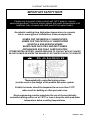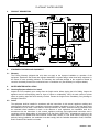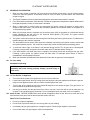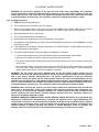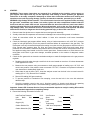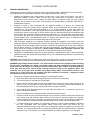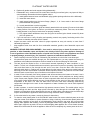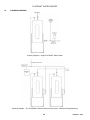
1
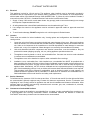
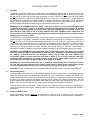
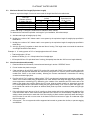
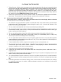
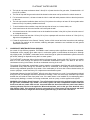
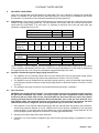
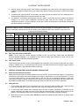
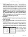
INSTALLATION & MAINTENANCE MANUAL PLATINUM WATER HEATER MODELS 199, 299 and 399(P, L or SS) A-PN (SANI) Installation and service must be performed by a qualified service installer, service agency or the gas supplier. IMPORTANT: THIS MANUAL CONTAINS INFORMATION REQUIRED FOR INSTALLATION, OPERATION AND MAINTENANCE OF THIS EQUIPMENT. READ AND FOLLOW THE INFORMATION IN THIS MANUAL AND ALL OTHER PROVIDED INSTRUCTIONS, LABELS AND MARKINGS BEFORE INSTALLING, OPERATING OR SERVICING THIS UNIT. TO THE INSTALLER: After installation, these instructions must be given to the equipment user or left near the appliance. SPECIAL INSTRUCTIONS TO THE OWNER: Retain this manual for future reference. These instructions contain important information that will help you in maintaining and operating this appliance. PVI INDUSTRIES, LLC • 3209 Galvez Ave. • Fort Worth, Texas 76111 • Tel 1-800-433-5654 • www.pvi.com 1 PV500-37 06/12 PLATINUM WATER HEATER 1. 2. 3. 4. 5. 6. 7. 8. 9. 10. 11. 12. 13. 14. 15. 16. TABLE OF CONTENTS Safety Considerations Product Description Standard Features and Equipment 3.1 Warranty Water Heater Installation 4.1 Checking Equipment Before You Install 4.2 Codes 4.3 Electrical 4.4 Location 4.5 Service Clearances 4.6 Clearances to Combustible Surfaces Venting 5.1 Vent System Design 5.2 Venting of Multiple Units 5.3 Maximum Allowed Vent Length 5.4 Vent Construction and Assembly 5.5 Horizontal and Vertical Venting Through a Wall or Roof Combustion and Ventilation Air 6.1 Vertical or Horizontal Remote Air Option 6.2 Remote Air Piping Design 6.3 Remote Air Piping of Multiple Units 6.4 Maximum Allowed Remote Combustion Air Inlet Length 6.5 Combustion Air Inlet Construction and Assembly 6.6 Horizontal and Vertical Remote Combustion Air Inlet Piping Condensate Neutralization & Disposal Gas Supply and Piping 8.1 Inlet Pressure 8.2 Appliance Isolation During Gas Supply Piping Pressure Test 8.3 Gas Connection 8.4 Gas Train and Controls Certification 8.5 Gas Control Trains General Information on Water Connections and Use 9.1 Water Inlet and Outlet Connections 9.2 Filling the Unit 9.3 Relief Valve 9.4 Thermal Expansion 9.5 Low Water Cutoff 9.6 Temperature Adjustment 9.7 Thermostat Settings 9.8 High Water Temperature Limit Control Sequence of Operation 10.1 For Your Safety 10.2 To Turn Off Gas to Appliance 10.3 Smell of Gas 10.4 Lighting Instructions NSF Food Service Installation Guidelines Startup Periodic Maintenance Plumbing Diagrams Platinum Notes Wiring Diagram Warranty forms ship separately with each product. 2 PV500-37 06/12 PLATINUM WATER HEATER 1. SAFETY CONSIDERATIONS WARNING: If the information in the supplied manual(s) is not followed exactly, a fire, explosion or exposure to hazardous materials may result, causing property damage, personal injury or loss of life. FOR YOUR SAFETY Do not store or use gasoline or other flammable vapors or liquids in the vicinity of this or any other appliance. WHAT TO DO IF YOU SMELL GAS Do not try to light any appliance. Do not touch any electric switch; do not use any phone in your building. Immediately call your gas supplier from a location away from your building and the smell of gas. Follow the gas supplier's instructions. If you cannot reach your gas supplier, call the fire department. Installation and service must be performed by a qualified installer, service agency or the gas supplier. This product contains, or may come to contain materials that have been identified as carcinogenic, or possibly carcinogenic to humans. Before installing, servicing or removing this product, read and follow the supplied instructions. WARNING: Installation and service must be performed by a qualified installer, service agency or the gas supplier, who must read and follow the supplied instructions before installing, servicing or removing this appliance. Refer to the information contained in this manual. Improper installation, adjustment, alteration, service or maintenance can cause property damage, personal injury, exposure to hazardous materials or loss of life. WARNING: Do not use this appliance if any part has been under water. Immediately call a qualified service technician to inspect the unit and to replace any part of the control system, all gas controls and all other items affecting safe appliance operation and which has been under water. WARNING: In an emergency shut the main gas supply valve to the appliance from a location safely away from the emergency. Failure to follow these instructions can cause property damage, personal injury, and exposure to hazardous materials or loss of life. PRODUCT SAFETY INFORMATION REFRACTORY CERAMIC FIBER PRODUCT WITH CRYSTALLINE SILICA WARNING: This product contains or may come to contain crystalline silica, which has been identified by the International Agency for Research on Cancer (IARC) as carcinogenic to humans. This product also contains refractory ceramic fibers, which have been identified by the IARC as possibly carcinogenic to humans. Avoid breathing fiber particulates and dust. RISKS: Airborne fibrous insulation is a possible cancer hazard by inhalation. Airborne crystalline silica may cause silicosis (lung disease) by inhalation. May cause temporary irritation to eyes, skin, and respiratory tract. PRECAUTIONARY MEASURES: Minimize airborne fibers with engineering controls. Use NIOSH/MSHA approved respirators as required (see MSDS). Wear long sleeved, loose-fitting clothing, eye protection and gloves. FIRST AID MEASURES: (If any of the irritations listed persists, seek medical attention) Eyes: Flush with water. Skin: Wash with soap and warm water. Ingestion: Do not induce vomiting. Get medical attention if gastrointestinal symptoms develop. Inhalation: Remove to fresh clean air. WARNING: If you are unfamiliar with the safe handling of refractory ceramic fiber products, or if you wish additional information prior to beginning any disassembly of the water heater or boiler that might expose refractory ceramic fiber materials, contact: Unifrax Corporation, 2351 Whirlpool Street, Niagara Falls, NY 14305-2413, 1-800-322-2293. IDENTIFICATION OF REFRACTORY CERAMIC FIBER MATERIALS (RCF): The burner, lower tank and upper and lower flue collector assemblies utilize RCF material. (The RFC materials are located within the product and not generally exposed except during service, disassembly or assembly.) 3 PV500-37 06/12 PLATINUM WATER HEATER IMPORTANT SAFETY NOTE It takes only 5 seconds of skin contact with 140°F water to cause a second degree burn! You must protect against high water temperatures at all lavatories, tubs, showers and other points of hot water contact. Accidental scalding from high water temperatures is a greater risk in some types of installations. Some examples are: HOMES FOR THE MENTALLY HANDICAPPED HOMES FOR THE PHYSICALLY HANDICAPPED HOSPITALS AND NURSING HOMES ELDER CARE FACILITIES AND REST HOMES ORPHANAGES AND CHILD CARE FACILITIES OTHER INSTALLATIONS - WHERE RESPONSE TO CONTACT WITH HOT WATER MAY BE SLOWER OR WHERE THE DANGER OF HOT WATER CONTACT IS GREATER Thermostatically controlled mixing valves must be used in the design of the potable hot water system. Potable hot water should be tempered to no more than 110°F when used for bathing or other personal uses. Good engineering practice mandates the use of thermostatically controlled mixing valves set at 120°F or less to keep the delivered water temperature below scalding temperatures. 4 PV500-37 06/12 PLATINUM WATER HEATER 2. PRODUCT DESCRIPTION 3. STANDARD FEATURES AND EQUIPMENT 3.1 Warranty The Factory Warranty (shipped with unit) does not apply to the improper installation or operation of the equipment. Experience has shown that improper installation or system design, rather than faulty equipment, is the cause of most operating problems. The warranty also excludes damage to the equipment caused by corrosive chemicals present in the mechanical room or combustion air. (See Warranty for complete details) 4. WATER HEATER INSTALLATION 4.1 Checking Equipment Before You Install Inspect the unit completely upon receipt from the freight carrier before signing the bill of lading. Inspect the appliance and all accompanying parts for signs of impact or mishandling. Verify the total number of pieces shown on packing slips with those actually received. Contact the freight carrier immediately if any damage or shortage is detected. 4.2 Codes The equipment shall be installed in accordance with the instructions in this manual, appliance markings and supplemental instructions and in compliance with those installation regulations in force in the local area where the installation is to be made. These shall be carefully followed in all cases. Authorities having jurisdiction shall be consulted before installation is made. In the absence of such regulations, the installation shall be in accordance with the instructions in this manual, appliance markings and supplemental instructions and in compliance with the latest edition of the National Fuel Gas Code, ANSI Z223.1. All appliances conform to the latest edition of the ASME Boiler and Pressure Vessel Code, Section IV, Part HLW. Where required by the authority having jurisdiction, the installation must also comply with the Canadian Association Code, CAN/CSAB149.1 and/or B149.2 and/or local codes. 5 PV500-37 06/12 PLATINUM WATER HEATER 4.3 Electrical This appliance is wired for 120-volt service. The appliance, when installed, must be electrically grounded in accordance with the requirements of the authority having jurisdiction or in the absence of such requirements, with the latest edition of the National Electrical Code ANSI/NFPA No. 70. When the unit is installed in Canada, it must conform to the CAE C22.1, Canadian Electrical Code and/or Local Electrical Codes. 1. Supply 15 amp, 120V service to each water heater. Any pump(s) used to connect the heater(s) to a storage tank requires a separate electrical circuit. 2. All wiring between the unit and field installed devices must be made with type T wire. 3. Line voltage wire exterior to the appliance must be enclosed in approved conduit or approved metal clad cable. 4. To avoid serious damage, DO NOT energize the unit until the system is filled with water. 4.4 Location These units are suitable for indoor installation only. Venting options and configurations are illustrated in the venting section. 4.5 1. Locate the unit so that if water connections should leak, water damage will not occur. When such locations cannot be avoided, it is recommended that a suitable drain pan, adequately drained, be installed under the unit. Under no circumstances is the manufacturer to be held responsible for water damage in connection with this unit, or any of it components. Water damage is not covered by the manufacturer’s warranty. 2. Units and associated electrical components and electrical connections, must be installed so they are protected from water (dripping, spraying, rain, etc.) during appliance operation and service. 3. The appliance must be placed on a level, non-combustible floor. Concrete over wood or wood embedded in concrete are not considered non-combustible. 4. The appliance must not be installed on carpet or other combustible floor coverings. 5. Installation over a combustible floor: Units installed over a combustible floor MUST be provided with a base consisting of a sheet of 3/8 inch minimum fireproof millboard (contact vendors such as unifrax.com or thermalceramics.com) with a 20-gage minimum sheet metal cover and no sized at least as large as the appliance base. Alternatively, the 3/8” minimum millboard can be incorporated as part of a housekeeping pad. If the housekeeping pad is a 6 inch or thicker solid concrete slab, millboard insulation is not required. This procedure must also be followed if combustibles, such as electrical conduit or wood supports, are located beneath the appliance and are imbedded in or attached to an otherwise non-combustible floor. A field-installed base must meet all local fire and safety code requirements. Service Clearances To facilitate service, clearance of 24" from the top and front, 14” from the rear and 8” from the right and left sides are recommended. Optional equipment may increase the clearance requirements. See the “Combustion and Ventilating Air” and “Venting” section for appliance vent and inlet air installation and clearance information. Allow sufficient space for installing and servicing connections such as water, gas, vent, combustion air, electrical, pump and other auxiliary equipment. 4.6 Clearances to Combustible Surfaces The appliance must not be installed on a combustible floor, on carpet, on other combustible floor coverings or on a non-combustible floor covering combustible material. Combustible materials are allowed to contact the PLATINUM® sides and top, however service clearances are recommended. 6 PV500-37 06/12 PLATINUM WATER HEATER 5. VENTING PLATINUM models with “SANI” in the model number are designed for operation with a "positive pressure vent system" constructed of locally obtained 4" schedule 40 or 80 solid CPVC pipe. Do not use PVC pipe of any type. Do not use CPVC pipe with cell/foam type construction (such as “CellCore”) or other non-solid CPVC plastic pipe. Larger solid CPVC pipe may be substituted; however, a solid CPVC increaser from 4” to the larger size must be used for connection to the stainless steel 4” male flue outlet from the water heater. Do not insulate the plastic vent pipe. Stainless steel venting listed by a nationally recognized testing laboratory for category IV positive pressure gas appliance venting may be used instead of plastic pipe venting. WARNING: On PLATINUM models with “SANI” in the model number, use only solid CPVC pipe venting or stainless steel venting listed by a nationally recognized testing laboratory for category IV positive pressure gas appliance venting. Use of PVC, ABS, pipe with cell/foam type construction, plastic vent pipe other than solid CPVC or use of venting materials other than specified in these instructions can result in failure of the venting system and/or exposure to carbon monoxide which can result in property damage, personal injury or death. The PLATINUM (except models with “SANI” in the model number, see above) is designed for operation with a "positive pressure vent system" constructed of locally obtained 4" schedule 40 or 80 solid PVC or CPVC pipe. Do not use PVC or CPVC pipe with cell/foam type construction (such as “CellCore”) or other non-solid PVC or CPVC plastic pipe. Larger solid PVC or CPVC pipe may be substituted; however a solid PVC or CPVC increaser from 4” to the larger size must be used for connection to the stainless steel 4” male flue outlet from the water heater. Do not insulate the plastic vent pipe. Stainless steel venting listed by a nationally recognized testing laboratory for category IV positive pressure gas appliance venting may be used instead of plastic pipe venting. WARNING: On PLATINUM, (except models with “SANI” in the model number, see above) use only solid PVC pipe, solid CPVC pipe or stainless steel venting listed by a nationally recognized testing laboratory for category IV positive pressure gas appliance venting. Use of ABS, pipe with cell/foam type construction, plastic vent pipe other than solid PVC or CPVC or use of venting materials other than specified in these instructions can result in failure of the venting system and/or exposure to carbon monoxide which can result in property damage, personal injury or death. WARNING: Do not vent this water heater into an existing or traditional gas vent or chimney or combine the vent with any other appliance. Such venting could result in failure of the venting system and/or exposure to carbon monoxide which can result in property damage, personal injury or death. CAUTION: DO NOT use ABS pipe in venting system. ABS can emit toxic fumes in the event of a building fire. 5.1 Vent System Design The PLATINUM water heater can be vented either vertically, through a ceiling or roof, or horizontally through a wall. From the flue outlet of the water heater the solid PVC, (PVC not allowed on models with “SANI” in the model number) solid CPVC venting or stainless steel venting listed by a nationally recognized testing laboratory for category IV positive pressure gas appliance venting can be routed in any direction except down. The vent must be installed and supported to slope downward toward the water heater vent connection with at least ¼ inch drop per linear foot of horizontal vent run, to allow proper drainage of accumulated condensation. Follow all requirements in the General “Venting” section of this manual and other instructions and markings for venting flue products to the outdoors, obtaining adequate combustion and ventilation air and general installation instructions. 5.2 Venting of Multiple Units Multiple PLATINUM models must not be vented into a common duct or breeching. Each unit must be independently vented in accordance with the instructions for either horizontal or vertical venting included above. 7 PV500-37 06/12 PLATINUM WATER HEATER 5.3 Maximum Allowed Vent Length (Equivalent Length) Maximum equivalent length of vent must not exceed the length identified in the table below: Vent Pipe Diameter (inches) 3” (Model 199 only) 4” (All Models) 5” (All Models) 6” (All Models) Equivalent length (in feet) 90° elbow 45° elbow 12 5 14 5 15 6 17 7 Maximum Equivalent Inlet Length (in feet) 80* 100 300 500 * Model 199 using 3” vent pipe is limited to 4-90° elbows or 8-45° elbows. To determine the maximum equivalent vent length of your installation, follow these steps: A. Add the total length of straight pipe (in feet). B. Multiply the number of 90° elbows used in vent system by the equivalent length of straight pipe specified in table above. C. Multiply the number of 45° elbows used in vent system by the equivalent length of straight pipe specified in table above. D. Add (A), (B) and (C) together to obtain the total feet of venting. This length must not exceed the maximum vent length identified in table above. Example: A 4" venting system of 25 ft. of straight pipe and two 90° elbows. Total straight pipe = 25 feet. Number of elbows (2) x 14 = 28 equivalent feet of straight pipe. 25 feet plus 28 feet = 53 equivalent feet of venting. (Acceptably less than the 100 foot vent length allowed.) 5.4 Vent Construction and Assembly 1. Read and follow the information, instructions and warnings in section “VENTING” above. 2. Do not insulate the plastic vent pipe. 3. Clean and deburr all solid PVC (solid CPVC required for models with “SANI” in the model number) pipe ends and the joint area and trial assemble the vent before joining with PVC cement (CPVC cement required for models with “SANI” in the model number), following the cement manufacturer’s instructions for making sound air and water tight joints. 4. Dry-fit a solid 4" PVC coupling or elbow (solid 4" CPVC vent pipe and components required for models with “SANI” in the model number) onto the appliance flue outlet. Remove the fitting and apply a liberal coating of room temperature vulcanizing (RTV) adhesive to the outside of the stainless steel flue outlet and to the inside of the plastic pipe coupling. Before the RTV sets, slide the plastic coupling or elbow back onto the RTV coated appliance flue outlet while rotating the pipe approximately 1/8 of a turn. Inspect and apply RTV to the inside and outside of the plastic to stainless steel joints to provide a continuous water and gas tight assembly. 5. Drill a pilot hole through the top of the 4" coupling or elbow socket and into the stainless steel appliance flue outlet and attach with a sheet metal screw (stainless steel screws are recommended). Repeat this step adding a sheet metal screw to each side of this first coupling or elbow socket to positively attach the fitting to the flue outlet. Do not drill or use a screw in the bottom of the flue connector or pipe, as condensate might drip from this point. 6. Vent support – The vent system should be supported at intervals no greater than six feet, to prevent sagging and distortion. 8 PV500-37 06/12 PLATINUM WATER HEATER 7. Testing for leaks - All joints in the vent system must be air and water tight. After the vent is assembled, close the end of the vent with a taped plastic bag or some other temporary closure. With the gas supply turned off, energize the combustion blower to apply air pressure to the vent system. Spray each joint and vent connection with commercially available leak detection liquid to confirm no air is escaping from any point. Repair any leaks and retest. After testing is complete, de-energize the combustion blower, wipe clean the leak detection liquid and REMOVE the temporary vent closure. 8. Attach to the outdoor end of the vent the required UL listed vent termination supplied with the PLATINUM water heater. This termination is required for proper operation and no substitution is allowed. 5.5 Horizontal and Vertical Venting Through a Wall or Roof Vent terminal locations, clearances, warnings and requirements stated in this manual apply, whether combustion air comes from the room or is ducted from outdoors. 1. The solid PVC vent pipe (solid CPVC required for models with “SANI” in the model number) must be sealed to the wall or roof at the point where it passes through the wall or roof, to prevent rain, insects or flue products from entering the living space. 2. The vent must be terminated with the UL-listed vent termination provided by PVI. 3. The vent terminal must have a minimum clearance of 4 feet (1.22 m) horizontally from, and in no case be located above or below, unless a 4 foot (1.22 m) horizontal distance is maintained from electric meters, gas meters, regulators and relief equipment. 4. The vent cap shall terminate at least 3 feet (0.91 m) above any forced air inlet within 10 feet (3.05 m). 5. The vent shall terminate at least 4 feet (1.22 m) below, 4 feet (1.22 m) horizontally from or 1 foot (0.3 m) above any door, window or building air inlet to the building. 6. The vent system shall terminate at least 1 foot (0.3 m) above grade and at least 1 foot (0.3m) above possible snow accumulation levels and shall terminate at least 7 feet (2.13 m) above grade when located adjacent to public walkways or gathering areas. 7. To avoid a blocked flue condition, keep the vent cap clear of snow, ice, leaves, debris, etc. 8. The vent must not exit over a public walkway, near soffit vents or crawl space vents or other areas where condensate or vapor could create a nuisance or hazard or cause property or could be detrimental to the operation of regulators, relief valves or other equipment. 9. A horizontal vent must extend one foot beyond the wall. 10. A horizontal vent terminal must not be installed closer than 3 feet (0.91m) from an inside corner of an Lshaped structure. 11. A vertical vent should exhaust outside the building at least 2 feet (0.61 m) above the highest point of the roof within a 10-foot (3.05 m) radius of the termination. 12. The vertical termination must be a minimum of 3 feet (0.91 m) above the point of exit. A vertical termination less than 10 feet (0.91 m) from a parapet wall must be a minimum of 2 feet (0.61 m) higher than the parapet wall. 13. Follow all requirements in the General “Venting” section of this manual and other instructions and markings for venting flue products to the outdoors, obtaining adequate combustion and ventilation air and general installation instructions. 9 PV500-37 06/12 PLATINUM WATER HEATER TYPICAL TERMINATION LOCATIONS FOR VERTICAL VENT PIPES Termination of less then 10 feet Follow all requirements in the General “Venting” section of this manual and other instructions and markings for venting flue products to the outdoors, obtaining adequate combustion and ventilation air and general installation instructions. Termination of more than 10 feet 10 PV500-37 06/12 PLATINUM WATER HEATER Horizontal Venting and Outside Combustion Air Follow all requirements in the General “Venting” section of this manual and other instructions and markings for venting flue products to the outdoors, obtaining adequate combustion and ventilation air and general installation instructions. Vertical Venting and Outside Combustion Air 11 PV500-37 06/12 PLATINUM WATER HEATER 6. COMBUSTION AND VENTILATION AIR Provisions for adequate combustion and ventilation air must be supplied to the mechanical room in accordance with these instructions and in compliance with Section 5.3, Air for Combustion and Ventilation of the latest edition of the National Fuel Gas Code, ANSI Z223.1 and/or CAN/CSA B149, Installation Codes or applicable provisions of the local building codes. The equipment room MUST be provided with two openings to assure adequate combustion air and proper ventilation. 1. If air is taken directly from outside the building: a. Combustion air opening, 1 square inch per 2000 Btu/h input. This opening must be located near the floor. b. Ventilation air opening, 1 square inch per 2000 Btu/h input. This opening must be located near the ceiling. 2. If air is taken from another interior space: Each opening specified above should have a net free area of one square inch for each 1000 Btu/h of input. WARNING: Adequate clean combustion air must be provided to the appliance. Under no circumstances should the appliance ever be under a negative pressure. Particular care should be taken when exhaust fans, compressors, air handling units, etc. may rob air from the appliance. The combustion air supply must be completely free of any chemical or fumes, which may be corrosive to the boiler. Some common chemical fumes which must be avoided are fluorocarbons and other halogenated compounds, most commonly present as refrigerants or solvents, such as Freon, trichloroethylene, perchlorethylene, chlorine, etc. These chemicals, when in contact with the equipment or when burned, form acids which quickly attack the tubes, flue collector, stack and other appliance and auxiliary equipment. The result of inadequate clean combustion air or negative pressure can be premature unwarranted product failure or unsafe operation producing carbon monoxide that could escape into the building which can result in property damage, personal injury or death. NOTE: This unit may be installed with an optional remote air intake system, which uses a make-up air duct to draw combustion air directly from outdoors. (See: Vertical and Horizontal Remote Air). 6.1 Vertical or Horizontal Remote Air Option The vertical or horizontal remote air system requires a factory or site installed remote combustion air inlet option package. If your water heater does not include this optional equipment and you wish to operate the water heater with vertical or horizontal remote air, contact your PVI sales representative or call the toll free telephone number located in this manual and on the water heater to purchase the “PLATINUM Remote Air Kit.” Do not attempt to fabricate this kit from locally available parts as it may cause unsafe operation. 6.2 Remote Air Piping Design The PLATINUM water heater can obtain remote air either vertically, through a ceiling or roof, or horizontally through a wall. Locally obtained 4" schedule 40 solid PVC pipe must be attached to the female 4" PVC remote air inlet connection at the rear lower jacket and be routed to outdoors. (This coupling can be unscrewed and reversed to obtain a 4" male connection point.) Do not use PVC pipe with cell/foam type construction or other non-solid PVC plastic pipe. Larger solid PVC pipe may be substituted; however a PVC increaser from 4" to the larger size must be used for connection to 4" PVC coupling exiting the rear lower jacket of the water heater. CAUTION: DO NOT use ABS pipe in venting system. ABS can emit toxic fumes in the event of a building fire. WARNING: Locate the termination of the combustion air inlet outdoors following the provided instructions and to minimize deflection of high winds off adjacent walls, buildings or shrubbery, which can cause flue gas recirculation and to minimize the opportunity for products of combustion to enter the building. Recirculation of flue gas (products of combustion drawn from the flue gas outlet into the combustion air inlet) can cause operational problems, premature unwarranted product failure or unsafe operation producing carbon monoxide. Exposure to carbon monoxide can result in property damage, personal injury or death. 12 PV500-37 06/12 PLATINUM WATER HEATER 6.3 Remote Air Piping of Multiple Units Remote air piping for Multiple PLATINUM models must not be connected into a common duct or breeching. Remote outside combustion air for each unit must be independently piped in accordance with the instructions for either horizontal or vertical remote air systems. Combustion air supplied from outdoors must be free of contaminants (see Combustion and Ventilation Air). To prevent recirculation of flue products in to the combustion air inlet, follow all instructions in this section. Follow all requirements in the General “Venting” section of this manual and other instructions and markings for venting flue products to the outdoors, obtaining adequate combustion and ventilation air and general installation instructions. 6.4 Maximum Allowed Remote Combustion Air Inlet Length (Equivalent Length) Maximum equivalent length of combustion air inlet must not exceed the length identified in the table below: Combustion Air Inlet Vent Pipe Diameter (inches) 3” (Model 199 only) 4” (All Models) 5” (All Models) 6” (All Models) Equivalent length (in feet) 90° elbow 45° elbow 12 5 14 5 15 6 17 7 Maximum Equivalent Inlet Length (in feet) 80* 100 300 500 * Model 199 using 3” vent pipe is limited to 4-90° elbows or 8-45° elbows. To determine the maximum equivalent combustion air inlet length of your installation, follow these steps: A. Add the total length of straight pipe (in feet). B. Multiply the number of 90° elbows used in inlet system by the equivalent length of straight pipe specified in table above. C. Multiply the number of 45° elbows used in inlet system by the equivalent length of straight pipe specified in table above. D. Add (A), (B) and (C) together to obtain the total feet of venting. This length must not exceed the maximum inlet length identified in table above. Example: How many equivalent feet is a 4" combustion air inlet system of 25 ft. of straight pipe and (2) 90° elbows? Total straight pipe = 25 feet. Number of elbows (2) x 14 = 28 equivalent feet of straight pipe. 25 feet plus 28 feet = 53 equivalent feet of inlet. (Acceptably less than the 100 foot inlet length allowed.) 6.5 Combustion Air Inlet Construction and Assembly 1. Clean and deburr PVC pipe ends and the joint area and trial assemble the vent before joining with PVC cement, following the PVC cement manufacturer’s instructions for making sound air and water tight joints. 2. Inlet support – The inlet piping system should be supported at intervals no greater than six feet, to prevent sagging and distortion. 3. Attach to the outdoor end of the PVC inlet pipe to the required UL listed termination that is supplied with the PLATINUM water heater. This termination is required for proper operation and no substitution is allowed 6.6 Horizontal and Vertical Remote Combustion Air Inlet Piping Through a Wall or Roof 1. The solid PVC inlet pipe must be sealed to the wall or roof at the point where it passes through the wall or roof, to prevent flue rain, insects or flue products from entering the living space. 2. The inlet air cap supplied with the optional remote air intake package MUST be used to adequately protect the air inlet from wind and weather. Do not substitute other caps. 13 PV500-37 06/12 PLATINUM WATER HEATER 3. The inlet air cap must terminate at least 3 feet (0.91 m) lower than the flue gas outlet, if located within a 10 foot (3.05 m) radius. 4. The inlet air cap and flue gas outlet should be located on the same roof top surface for vertical remote air. 5. For horizontal remote air, it is best to locate the inlet in a wall with wind pressure similar to the wind pressure on the vent. 6. The inlet cap must be installed at least one foot (0.3 m) above the rooftop or at least 18" above grade and at least one foot (0.3 m) above possible snow levels. 7. To avoid a blocked inlet condition, keep the inlet cap clear of snow, ice, leaves, debris, etc. 8. A horizontal remote air inlet must extend one foot beyond the wall. 9. A horizontal remote air inlet terminal must not be installed closer than 3 feet (0.91m) from an inside corner of an L-shaped structure. 10. A vertical remote inlet less than 10 feet (0.91 m) from a parapet wall must be a minimum of 2 feet (0.61 m) higher than the parapet wall. 11. Follow all requirements in the General “Venting” section of this manual and other instructions and markings for venting flue products to the outdoors, obtaining adequate combustion and ventilation air and general installation instructions. 7. CONDENSATE NEUTRALIZATION & DISPOSAL As a result of high efficiency operation, PLATINUM water heaters produce significant amounts of condensate. Condensate occurs naturally when water vapor in combustion gases is cooled below the dew point. Although only slightly acidic, PLATINUM condensate can be routed through an optional neutralization system to become pH neutral, allowing for disposal into any drain or sewer system. The PLATINUM condensate drain exits through the left support stand. Connect this 3/4" PVC pipe to a suitable drain or to the drain through an optional PVI condensate neutralization system. This drain is the exit for condensate occurring in the heater, as well as condensate occurring in the vent. The optional PVI condensate neutralization system contains a neutralization bath filled with crushed limestone. Condensate slowly flows through the limestone bed and is neutralized, thus avoiding chemical treatment or dilution using substantial quantities of tap water. If the condensate pH is lower than 4 when checked with a pH meter or pH paper, consult the factory for a replacement neutralization system. Condensate drainage from the PLATINUM will only occur after a recovery run cycle. If no condensate is drained during this time, the drainpipe should be inspected for blockage. There is a see through cleanable trap located beneath the unit inside the lower front jacket cover. If the water heater is not installed on a housekeeping pad to ensure gravity drainage, a means of removing condensate, such as a pump, must be applied to the system. WARNING: High Voltage Shock Potential - Turn off all electrical service to the appliance when accessing the gas valve, condensate trap, blower, hot surface ignitor and other components located inside the lower front and rear panels. After access, close and fasten the lower front and rear panel covers before restoring electrical service to the appliance. Wires and terminals, such as the gas valve terminals carry High Voltage (120V). If the electrical service is not turned off, or if the covers are not replaced, and these terminals are touched, a dangerous shock causing personal injury or loss of life could occur. 14 PV500-37 06/12 PLATINUM WATER HEATER 8. GAS SUPPLY AND PIPING Verify unit is supplied with type gas specified on rating plate. This unit is orificed for operation up to 2000 feet altitude. Unit derated 4% per 1000 feet above 2000 feet elevation. Consult Factory for installations above 2000 feet elevation. Conversions must be reviewed and authorized by factory personnel. 8.1 Inlet Pressure - Inlet pressure is measured at the pressure tap located on the side of the main gas cock located outside the right water heater support leg. The inlet pressure must remain within the minimum and maximum values while the PLATINUM® is at rest, while it is operating at maximum firing rate and while other gas equipment or appliances are on or off. INLET PRESSURE Max. (Inches-Water Column) Min. (Inches-Water Column) Nat. Gas 10.5" 4.5" LP 13" 11" CONVERT FITTINGS TO EQUIVALENT STRAIGHT PIPE Diameter Pipe (inches) Equivalent Length of Straight Pipe BTU INPUT 199,000 299,000 399,000 3/4" 1" 1-1/4" 1-1/2" 2" 3" 4" 5" 2' 2' 3' 4' 5' 10' 14' 20' SINGLE UNIT SUGGESTED GAS PIPE SIZE Distance from Meter (In feet) 0-50' 51-100' 101-200' 201-300' 1" 1" 1-1/4" 1-1/2" 1" 1-1/4" 1-1/4" 1-1/2" 1-1/4" 1-1/4" 1-1/2" 1-1/2" 301-500' 2" 2" 2" Use the values in “Convert Fittings to Equivalent Straight Pipe” to add the equivalent straight pipe for each elbow or tee to obtain the total distance from the meter. Use this corrected total distance from the meter for determining the suggested pipe size in the “Single Unit Installation Suggested Gas Pipe Size” table. 8.2 Appliance Isolation During Gas Supply Piping Pressure Test 1. The appliance and its individual shutoff valve must be disconnected from the gas supply piping system during any pressure testing of that system at test pressures in excess of 1/2 PSI (3.5 kPa). 2. The appliance must be isolated from the gas supply piping system by closing its individual manual shutoff valve during any pressure testing of the gas supply piping system at pressures equal to or less than 1/2 PSI (3.5 kPa). 3. The appliance and its gas connection must be leak-tested before placing it in operation. 8.3 Gas Connection WARNING: High Voltage Shock Potential - Turn off all electrical service to the appliance when accessing the gas valve, condensate trap, blower, hot surface ignitor and other components located inside the lower front and rear panels. After access, close and fasten the lower front and rear panel covers before restoring electrical service to the appliance. Wires and terminals, such as the gas valve terminals carry High Voltage (120V). If the electrical service is not turned off, or if the covers are not replaced, and these terminals are touched, a dangerous shock causing personal injury or loss of life could occur. 1. Safe operation of unit requires adequate gas supply with the required static and dynamic (flow) pressures. Actual piping selection depends on many variables that must be carefully considered by the gas piping system designer. Do not select gas pipe sizes based only on the supplied tables. These tables are for use by the gas piping system designer as a reference in checking pipe size selections. 2. Gas pipe size may be larger than heater connection. 3. Installation of a union between the appliance gas valve and the gas supply piping is suggested for ease of service. 15 PV500-37 06/12 PLATINUM WATER HEATER 4. Install a manual main gas shutoff valve between the appliance gas valve and the gas supply piping when needed for appliance isolation during gas supply piping pressure testing (see above) or when Local Codes require. 5. A sediment trap (drip leg) MUST be provided in the inlet of the gas connection to the unit installed per the sediment trap manufacturer’s instructions and/or local code. 6. The appliance combination valve/regulator bias port utilizes a vent limiter and must respond to pressure changes in the lower burner compartment (formed by lower front and rear cowling), as opposed to atmospheric pressure. For proper operation, do not alter, connect to atmosphere or relocate the combination gas valve/regulator or its bias port. MULTIPLE UNIT INSTALLATIONS GAS PIPING SIZE CHART Maximum Capacity of Pipe in Thousands of BTU’s per hour for gas pressures of 14 Inches Water Column (0.5 PSIG) or less and a pressure drop of 0.05 Inch Water Column (Based on NAT GAS, 1025BTU’s per Cubic Foot of Gas and 0.60 Specific Gravity). Nominal Length of Pipe in Straight Feet Iron Pipe 10 20 30 40 50 60 70 80 90 100 125 150 175 200 Size, Inches 369 256 205 174 155 141 128 121 113 106 95 86 79 74 3/4 697 477 384 328 292 267 246 256 210 200 179 164 49 138 1 1400 974 789 677 595 543 502 472 441 410 369 333 308 287 1 1/4 2150 1500 1210 1020 923 830 769 707 666 636 564 513 472 441 1 1/2 4100 2820 2260 1950 1720 1560 1440 1330 1250 1180 1100 974 871 820 2 6460 4460 3610 3100 2720 2460 2310 2100 2000 1900 1700 1540 1400 1300 2 1/2 11200 7900 6400 5400 4870 4410 4000 3800 3540 3300 3000 2720 2500 2340 3 23500 16100 13100 11100 10000 9000 8300 7690 7380 6870 6150 5640 5130 4720 4 8.4 Gas Train and Controls Certification NOTE: The gas train and controls assembly provided on this unit have been tested under the applicable American National Standard or UL standard to meet minimum safety and performance criteria such as safe lighting, combustion and safety shutdown operation. 8.5 Gas Control Trains All gas control trains include a union, located between the combination valve and blower and which may contain a factory installed orifice, a combination gas valve and a final manual shutoff valve (with gas supply pressure tap) located outside the right side water heater support leg. 9. GENERAL INFORMATION ON WATER CONNECTIONS AND USE 9.1 Water Inlet and Outlet Connections Make inlet and outlet water connections directly to the two inch NPT bolt-on bronze tank flanges. Over tightening connections to the flanges may cause damage to the flange or tank and are not covered by warranty. For ease of service, install unions on inlet and outlet piping to the unit. Do not use galvanized nipples to make tank connections as these will cause corrosion and rust. Piping and components connected to the water heater must be suitable for potable water, for the water temperatures they will experience and for their application. 9.2 Filling the Unit 1. Fill the system with water. To be sure that the unit is not “air bound,” open the relief valve. Leave the valve open until a steady flow of water is observed. Close valve and complete filling the system. 2. In hard water areas, potable water treatment should be used to reduce introduction of minerals into the system. Minerals in the water can collect on the tubes and heat-exchanger surfaces reducing the life of the product. Heat exchanger failure due to scale accumulation is not covered by the product warranty. 3. Make sure there are no system leaks. DO NOT use petroleum based stop-leak products. All system leaks must be repaired. 16 PV500-37 06/12 PLATINUM WATER HEATER 9.3 Relief Valve PLATINUM® water heaters are supplied with a combination temperature and pressure relief valve sized in accordance with ASME Boiler and Pressure Vessel Code, Section IV. (Optional AGA-rated relief valve is available when required by local code) The water heater must not be operated without a correctly installed, properly sized and properly operating relief valve. If a replacement relief valve is required, it must be of the automatic reset type combination temperature-pressure relief valve complying with the Standard for Relief Valves for Hot Water Supply Systems, ANSI Z21.22 / CSA 4.4, must not be less than the hourly Btu input rating of the water heater as stated on the information decal located on the front control panel and must not have a relieving pressure exceeding the 160 psi maximum working pressure of the water heater. The relief valve(s) must be threaded directly into the dedicated relief valve fitting located in the top of the tank and the relief valve discharge must be plumbed to an appropriate floor drain. The discharge line must allow complete drainage of the valve and line. Relief valves should be manually operated at least once a year and if it fails to freely discharge water or fails to reseat following testing, it must be replaced with a like relief valve as described above. WARNING: Do not install a reducing coupling, valve or other restriction between the tank and the relief valve or between the relief valve discharge and a suitable floor drain. Such restriction could prevent the valve from fully relieving if temperature or pressure settings are exceeded, which could result in property damage, violent tank expansion or bursting, exposure to hazardous materials, personal injury or death. WARNING: The relief valve discharge must be piped to a suitable floor drain to avoid exposure to hot discharge water during relief valve operation. Exposure to hot discharge water can cause water damage and/or burns resulting in property damage, personal injury or death. 9.4 Thermal Expansion A relief valve that discharges periodically may be due to thermal expansion in a closed system, such as a water heater installed in a system closed by components, such as a backflow preventer or check valve in the cold water supply or a closed heating loop. These systems must be provided with means to control expansion. Contact a boiler or plumbing professional to resolve this situation. Do not plug the relief valve. 9.5 Low Water Cutoff (if equipped) Low water cutoffs must be installed when required by the authority having jurisdiction. Proper function of low water cutoffs should be verified every six months. 9.6 Temperature Adjustment This unit has an adjustable thermostat to control water temperature. See temperature adjustment procedure in this manual. The thermostat is factory pre-set at approximately 120°F. Households with small children or disabled individuals may require 120ºF or lower temperature setting to reduce risk of scald injury. Set the thermostat or program the temperature control to the lowest settings that will satisfy hot water demands and prevent risk of scald injury. Some states may require a lower temperature setting. Check for local requirements governing the temperature setting. Remember, no water heating system will provide exact temperature at all times. Allow a few days of operation at this setting to determine the correct temperature setting consistent with your needs. NOTE: (1) This water heater, when set at the lower temperature setting, is not capable of producing hot water of sufficient temperature for sanitizing purposes. (2) Higher stored water temperature increases the ability of the water heater to supply desired quantities of hot water, however remember: WARNING: Hotter water increases the risk of scald injury. 17 PV500-37 06/12 PLATINUM WATER HEATER WARNING: Setting the temperature selector to higher settings provides hotter water, which increases the risk of scald injury. If this appliance is used to produce water that could scald if too hot, such as domestic hot water use, reduce the water temperature setting and utilize a system or point-of-use temperature limiting valve to obtain a water temperature of 120ºF or less. See the “IMPORTANT SAFETY NOTE” concerning hot water temperatures located near the front of this manual. WARNING: Should overheating occur or the gas supply fails to shut off, do not turn off or disconnect the electrical supply to the appliance. Instead, shut off the gas supply by turning off the manual gas valve external to the appliance. Turning off or disconnecting the electrical supply to the appliance during these conditions could result in a fire, explosion or exposure to hazardous materials, causing property damage, personal injury or loss of life. 9.7 Thermostat Settings The adjustable operating temperature control is located between the upper and lower front control panel covers. This control utilizes a temperature sensing thermistor located in the control flange on top of the tank. Follow the safety instructions and warnings included in this manual and with the product, when adjusting the set point of the operating temperature control to deliver the desired water temperature. The setpoint (SET) determines the desired stored water temperature in the tank and is factory set at approximately 120°F. If the tank temperature decreases below the set point a call for heat sequence is activated. The heating sequence is turned off when the tank temperature again reaches the set point value. To View the Setpoint 1. Press and quickly release the “SET” key. This will display the setpoint for 5 seconds. To Change the Set Point 1. Press and hold the “SET” key for at least 2 seconds to enter the setpoint change mode. 2. The setpoint is displayed and the LEDs of the first and third digits blink. 3. To change the value, use the “UP” and “DOWN” keys. 4. The new value can be stored either by pressing the “SET” key (the control restores temperature display) or by waiting the exit time-out to expire (15 seconds). Key Combinations 1. TO UNLOCK THE KEYBOARD: Press and hold the “UP” + “DOWN” keys for 3 seconds. When the “PON” flashing message is displayed, the keys are unlocked. 2. TO LOCK THE KEYBOARD: Press and hold the “UP”+ “DOWN” keys for 3 seconds. When the “POF” flashing message is displayed, the keys are locked. 3. TO RETURN TO TEMPERATURE DISPLAY: Press the “SET” +”UP” keys. 9.8 High Water Temperature Limit Control All PLATINUM water heaters are equipped with preset limit and high limit controls to provide control of the maximum discharge water temperature. These controls are located inside the upper front control panel and are not user adjustable. WARNING: High Voltage Shock Potential - Turn off all electrical service to the appliance when accessing limit or high limit controls located inside the control panel. After access, close and fasten the panel cover before restoring electrical service to the appliance. Wires and terminals carry High Voltage (120V). If the electrical service is not turned off, or if the panel cover is not replaced, and these terminals are touched, a dangerous shock causing personal injury or loss of life could occur. 18 PV500-37 06/12 PLATINUM WATER HEATER 10. SEQUENCE OF OPERATION: 1. When the water heater is powered (120 volts) through the ON-Off control switch, the Hot Surface Ignition Control will reset and perform a self-check routine to verify no flame is present before the call-for-heat sequence begins. 2. The Digital Temperature Control (thermostat) displays the actual water temperature in the tank. 3. If the actual water temperature inside the tank is below the programmed temperature setpoint differential of the digital temperature control, a call-for-heat is activated. 4. When a call-for-heat is received from the thermostat, the ignition control will perform a safety timing sequence and flame check. If all checks are successfully passed, the combustion blower is energized for a 15-second pre-purge period. 5. When the pre-purge period is complete, the hot surface igniter (HSI) is energized for a 40-second heat-up period, followed by the gas valve for the 4-second trial-for-ignition (TFI) period. The igniter remains energized throughout the TFI period. 6. The ignition control will monitor for flame through the HSI during the trial for ignition period. If a valid flame is detected the gas valve remains energized. 7. The thermostat and main burner flame signal are constantly monitored by the ignition control to assure that the system operates properly. The control will continuously monitor the flame during the heating period. 8. If the burner fails to light or the flame is not detected during the first TFI, the gas valve is deenergized. Following a purge period, the ignition control will make three TFI attempts before locking out. 9. If the flame signal is lost while the burner is operating, the ignition control will de-energize the gas valve. Following a purge period, the ignition control will make three TFI attempts before lockout. If flame is reestablished, normal operation resumes. 10. When the thermostat is satisfied and the demand for heat ends, the gas valve is de-energized. 10.1 For Your Safety Read Before Operating WARNING: If you do not follow these instructions exactly, a fire or explosion may result causing property damage, personal injury or loss of life. Manual Gas Valve (Cock) 10.2 To Turn Off Gas To Appliance 1. Turn off all electric power to the appliance if service is to be performed. 2. Locate manual gas shutoff valve by looking where the gas pipe enters the appliance and follow the gas line away from the appliance jacket until you reach the manual gas shutoff valve. 3. Turn the gas off by rotating the gas valve handle 90 degrees to aim across the pipe. (The gas valve is on when the handle is parallel to the gas pipe). 4. Use only your hand to turn the gas control lever. Never use tools. If the lever will not turn by hand, don’t try to repair it, call a qualified service technician. Force or attempted repair may result in a fire or explosion. 10.3 Smell for Gas - BEFORE OPERATING, smell around the appliance area for gas. Be sure to smell next to the floor because some gas is heavier than air and will settle to the floor. What To Do If You Smell Gas Do not try to light any appliance. Do not touch any electric switch; do not use any phone in your building. Immediately call your gas supplier from a neighbor’s phone. Follow the gas supplier’s instructions. If you cannot reach your gas supplier, call the fire department. 19 PV500-37 06/12 PLATINUM WATER HEATER WARNING: Do not use this appliance if any part has been under water. Immediately call a qualified service technician to inspect the appliance and to replace any part of the control system and any gas control that has been under water. Use of an appliance with parts that have been under water can result in property damage, personal injury, fire, explosion, exposure to hazardous materials, or death. 10.4 Lighting Instructions 1. STOP! Read the safety information. 2. Turn manual gas cock clockwise to the “ON” position. 3. Wait five (5) minutes to clear out any gas. If you smell gas, STOP! Follow "SMELL FOR GAS” and “WHAT TO DO IF YOU SMELL GAS" in the safety information. If you don't smell gas go on to the next step. 4. Adjust thermostat to obtain a call for heat. 5. Turn On all electrical power to the appliance. 6. Press rocker switch located on the front control panel to “ON” position. 7. This appliance is equipped with an ignition device that automatically lights the burners. DO NOT try to light the burners by hand. 8. If the appliance will not operate, follow the instructions "TO TURN GAS OFF TO APPLIANCE" and call your service technician or gas supplier. 9. Test Ignition System Shutoff Device after placing the appliance in operation: Locate the gas supply manual valve just outside the lower right water heater support stand. While the unit is firing, turn gas off to the burner by closing this manual valve. The ignition system safety shutoff device should de-energize the main gas valve, because main burner flame is lost. After successful testing, reopen the manual valve and reset the ignition safety shutoff device by turning the rocker power switch off, waiting three seconds then turning the power back on. After resetting the ignition safety shutoff device, verify normal appliance operation. WARNING: The hot surface gas igniter (HSI/glow bar) and the hot surface ignition module are not repairable and a faulty hot surface gas igniter or faulty hot surface ignition module must be replaced with a new, factory specified replacement part. The ignition characteristics of this PVI Industries specified hot surface gas igniter and hot surface ignition module are unique and replacements are only available from PVI Industries or a PVI Industries authorized representative. Any modification, attempts to repair, or part substitution will invalidate the warranty and may create hazardous conditions that result in property damage, personal injury, fire, explosion, exposure to hazardous materials or death. WARNING: When servicing the controls, use exact, Factory authorized, replacement parts and label all wires prior to disconnection. Verify proper operation after servicing. Incorrect parts substitution and wiring errors can cause damage, improper operation, fire, carbon monoxide and other unexpected and unsafe conditions that could result in property damage, personal injury, fire, explosion, exposure to exposure to hazardous materials or death. WARNING: IMPROPER COMBUSTION MAY CAUSE SERIOUS INJURY OR DEATH. PVI recommends this appliance be installed and commissioned by a qualified gas appliance service agent. Additionally, PVI recommends a seasonal or annual combustion evaluation be performed by a qualified service agent to confirm proper combustion, with a carbon monoxide level no higher than 200 ppm, exhausting to the outdoors through a properly operating flue system. If Carbon Monoxide, which is colorless and odorless, enters an occupied space it can result in property damage, personal injury or death. 20 PV500-37 06/12 PLATINUM WATER HEATER 11. NSF FOOD SERVICE INSTALLATION GUIDELINES All PLATINUM® water heater models are listed to NSF 5-2000e. This section provides additional information for architects, designers, and contractors in food service installations requiring compliance with NSF codes. NSF/ANSI 5 - 2000e establishes health and sanitation requirements for the materials, design and construction of commercial water heaters. All Platinum® water heaters are certified for compliance with NSF-5 and ANSI Z21.10.3 by Underwriters Laboratories, Inc. and are therefore recognized as suitable for installation and use in commercial food service appllications when installed and used according to these instructions. WARNING: Do not use a pressurized water source to clean this water heater. If the food service installation requires pressurized washing, the water heater must be isolated from water spray. Failure to isolate the heater from pressurized water may cause a hazardous condition resulting in property damage or high voltage electrical shock, causing personal injury or death. Platinum® water heaters must be purchased with the “SANI” option where water temperatures exceeding 165ºF are required. All warranties, expressed or implied, may be voided if a Platinum® water heater without the factory installed “SANI” option is operated at temperatures exceeding 165ºF. Refer to the “Temperature Setting” section of this manual for instructions to adjust the thermostat to the desired temperature. NSF Installation - The NSF 5 listed Platinum® water heater requires no modification to become NSF 5 compliant, is designed to supply potable hot water and is not intended or suitable for other purposes. Where feasible, the water heater should be located seperate from food and utensil handling areas. When this is not possible in a food service installation, the water heater must be sealed to the floor to prevent water from accumulating underneath. The floor must be clean, smooth and level for adequate sealing. Seal the water heater to the floor using an NSF listed RTV sealant (such as Red Devil 0826, Saf-T-Lok 732 or RTV 102). Follow the manufacturers instructions to lay a bead of sealant between the edge of the heater base and the floor. Use the figure below to located and install ½” diameter black plastic plug caps (supplied in the bag that also contains the Instruction manual) to close the four holes in the base. NSF Service and Maintenance - NSF 5 for food service installations require the appliance and its installation to prevent harborage of vermin. T tight construction of the properly installed and assembled heater enclosure does not provide a haven for pests. The jacket and all fastners must be replaced whenever removed for service. Before replacing and fastening the jacket, inspect and replace any damaged weather striping. This weather stripping closes gaps between the jacket and steel frame. RTV Sealant Plug Base 21 PV500-37 06/12 PLATINUM WATER HEATER 12. STARTUP WARNING: These startup instructions are prepared for a qualified service installer, service agency or gas supplier and require and rely on the experience and training of these qualified gas appliance technicians to be safely completed. Attempting to follow these instructions without such training and experience can result in property damage, exposure to hazardous materials, personal injury or death. WARNING: High Voltage Shock Potential - Turn off all electrical service to the appliance when accessing the gas valve, condensate trap, blower, hot surface ignitor and other components located inside the lower front and rear panels. After access, close and fasten the lower front and rear panel covers before restoring electrical service to the appliance. Wires and terminals, such as the gas valve terminals carry High Voltage (120V). If the electrical service is not turned off, or if the covers are not replaced, and these terminals are touched, a dangerous shock causing personal injury or loss of life could occur. 1. Remove lower front jacket cover to expose the burner and gas train assembly. 2. Visually check that all components are intact and no damage has occurred during transit or installation. 3. Check all connections within the control cabinet. A loose wire connection could cause intermittent shutdowns. 4. Check the inlet/supply gas pressure before startup, using a U-tube manometer or a 0 to 28" W.C. pressure gauge for inlet gas pressure (This is the pressure measured before all components in the gas train). The manometer must stay connected throughout the testing to monitor the inlet gas pressure while the burner is firing. Record static pressure when not firing and record flow pressure while firing and ensure these pressures do not exceed the maximum inlet pressure and is not below the minimum inlet pressure shown on the appliance rating plate located on the front control panel door. Pressures above or below those on the rating plate could result in gas valve damage, unreliable operation or the creation of dangerous carbon monoxide. 5. Check the flue gases with an electronic combustion analyzer to make final adjustments to the gas pressure regulator: a. Readings should be taken through a small hole in the vent located no more than 12 inches downstream of the appliance flue outlet. b. Measure the vent pressure using a manometer or draft gauge capable of reading up to 1/2" W.C. and record vent pressure. Vent pressure must not exceed +0.4" W.C., Excessive vent pressure indicates a vent obstruction or inadequately sized vent. c. When water in tank is above 120°F, insert the analyzer sensor into the hole in the vent and record O2 reading (4% to 7.5%). Record CO2 if available. d. Record CO reading (200 ppm maximum). e. To prevent products of combustion from escaping, cover the test hole in the vent with aluminum adhesive tape. f. Check the operating control to be sure it functions properly by lowering and raising the operating temperature setting (see section “Thermostat Setting”) causing the burner to cycle on and off. Important: Contact PVI Customer Service if any recommended setpoint or analysis reading falls outside of the recommended ranges before completing startup. 6. Record the following information for future use: Inlet Flow Gas Pressure Inlet Static Gas Pressure " W.C. Oxygen (O2) % Carbon Dioxide CO2 % Vent Pressure Gross Vent Temperature Less Room Temperature = Net Vent Temperature Carbon Monoxide (CO) ppm Test Date: " W.C. 22 " W.C. °F °F °F PV500-37 06/12 PLATINUM WATER HEATER 13. PERIODIC MAINTENANCE Listed below are items that must be checked to insure safe reliable operation. Maintenance must be performed by a qualified service or maintenance provider. Verify proper operation after servicing. 1. Examine the appliance and venting system at least once a year. Check more often in first year to determine inspection interval. Check all joints and pipe connections for tightness, corrosion or deterioration. Clean screens in the venting air intake system as required. Have the entire system, including, but not limited to, the burner, heat exchanger and venting system, periodically inspected by a qualified service agency. 2. Exposure to Dusty or Dirty Combustion Air: An appliance installed in a dust or dirt contaminated atmosphere must have periodic burner inspection where those contaminants can be drawn into the combustion air. The burner should be checked on a 3 to 6 month schedule or more often, based on severity of contamination, until an appropriate interval can be determined by inspection experience. If an air filter box is used to remove dust or dirt, be certain it does not restrict free airflow into the appliance and that the filters are periodically cleaned. Inadequate combustion air or non-combustible particulate matter such as dust, dirt, dryer lint, concrete dust, dry wall dust or the like can block burner ports and cause unsafe operation and a non-warrantable failure. To inspect and clean the burner, a qualified service agent/installer should use the procedures described in item 5 & 6 below. 3. Heat Exchanger Inspection and Cleaning: Properly installed and adjusted units seldom need heat exchanger cleaning. If a blocking amount of dust or lint has formed or is forming, the heat exchanger must be cleaned and air born debris problem corrected. A blocked heat exchanger can cause unsafe operation and will reduce efficiency. To inspect and clean the heat exchanger, a qualified serviceman or installer should follow the procedures described in “Burner and/or Fireside Heat Exchanger Inspection and Cleaning,” other instructions in this manual and in other provided instructions and labels. 4. All gaskets on disassembled components must be replaced on reassembly with exact, Factory Authorized, replacement parts only. Gasket kits are available from your PVI Industries Representative or by contacting PVI Industries, LLC. CAUTION: Label all wires prior to disconnection when servicing controls, so they can be reconnected in their original and correct locations. Misconnected wiring can cause improper and dangerous operation. WARNING: High Voltage Shock Potential - Turn off all electrical service to the appliance when accessing the gas valve, condensate trap, blower, hot surface ignitor and other components located inside the lower front and rear panels or in the front electrical control panel. After access, close and fasten the lower front and rear panel covers before restoring electrical service to the appliance. Wires and terminals, such as the gas valve terminals carry High Voltage (120V). If the electrical service is not turned off, or if the covers are not replaced, and these terminals are touched, a dangerous shock causing personal injury or loss of life could occur. 5. Burner and/or Fireside Heat Exchanger Inspection and Cleaning Procedure: a. Write notes and/or take pictures during this process to aid in correct reassembly. b. Turn off main power to unit and turn off gas supply. c. Remove the hot surface igniter and set safely aside (Do not touch the black heating surface of the igniter, as oils from your hand can cause early failure. Take care during removal and reassembly, as the black heating element is very easy to break when not properly installed.) d. Tag to identify then disconnect wires to the gas valve and blower, etc., as required to remove the blower and gas train assembly. e. Remove the blower-to-burner gasket and then carefully remove the burner. f. If the inner screen of burner is blocked with dust or dirt, remove the screen from the body of the burner and carefully clean with soap and water. While the inner screen is removed, inspect and if needed, clean the main burner body. Take care not to damage the inner screen or burner body by avoiding the use of stiff brushes or abrasive materials. Reinsert inner screen into the burner body when clean. g. To inspect inside the flue collector, the combustion chamber or the fire tubes and baffles, disconnect the vent, condensate drain and pressure switch tubing then unbolt and remove the flue collector/bulkhead assembly, being careful not to damage the refractory attached to the top of this assembly. It is recommended practice to replace this refractory with new refractory when it is exposed during servicing. The refractory must be replaced before operating the appliance, if it is damaged. 23 PV500-37 06/12 PLATINUM WATER HEATER h. Replace all gaskets and seals exposed during disassembly. i. Reassemble unit in reverse order. Be careful when inserting hot surface ignitor, any impact is likely to cause brakeage. Remember the burner/gasket order is: 1) Install gasket between burner and bulkhead. (align gasket openings with those in the bulkhead) 2) Insert and center burner. 3) Install second gasket over the burner flange. (Steps 1, 2, & 3 must result in the burner flange pressed between two gaskets.) 4) Loosely attach blower over the top gasket j. Carefully reinsert the hot surface ignitor and loosely attach with thumb screws. (Do not touch the black heating surface of the igniter, as oils from your hand can cause early failure. Take care, as the black heating element is very easy to break when not properly installed.) 1) Fully tighten blower attachment nuts, then snug the hot surface ignitor thumb screws fully down plus one quarter turn. k. Cycle unit and test to verify all safety and operating controls are properly functioning and the flue collector to chamber connection is free of leaks. 6. Inspect low water cutoffs and relief valves for proper operation at every six months, or more often if indicated by inspection. 7. Keep appliance area clear and free from combustible materials, gasoline, other flammable vapors and liquids. WARNING: FIRE AND EXPLOSION HAZARD – Can result in serious injury or death. Do not store or use gasoline or other flammable vapors and liquids in the vicinity of this or any other appliance. Storage of or use of gasoline or other flammable vapors or liquids in the vicinity of this or any appliance can result in property damage, personal injury, fire, explosion, exposure to hazardous materials or death. 8. Check frequently to be sure the flow of combustion and ventilation air to the boiler is not obstructed. 9. All replacement parts are available through your PVI Representative or you may contact the Factory for assistance at the address and telephone number located on the first and last page of this manual. 10. The tank should be flushed at two- or three-month intervals depending on water conditions in your location. To flush, turn off electrical disconnect switch to prevent the burner from operating. Open the drain valve and allow water to flow through the tank until it runs clear. Close the drain valve and turn the electrical switch back on. Draining two or three gallons from the bottom of the tank on a weekly basis will also help prevent the accumulation of sediment. Water impurities consist of fine particles of soil and sand, which will settle out and form a layer of sediment on the bottom of the tank. 11. A scale of lime will normally form during operation and will accumulate on the bottom of the tank. Lime is formed from naturally occurring mineral compounds in the water, which precipitate out during heating cycles. Some water supplies contain more of these compounds than others and scale buildup will occur more rapidly. Other factors affecting the rate of scale buildup are the amount of hot water used and the temperature of the water. The more hot water used, the more fresh water containing scale-forming compounds is brought into the tank. As the temperature of water increases, the rate of scale deposition will increase. 12. If scale is present, it can be loosened with a high-pressure stream of water. The smaller pieces can be flushed through the drain and the larger pieces removed by hand through the removable flange. The frequency of inspections will be determined by the rate of scale buildup. Intervals as short as 30-60 days may be recommended in applications where scale forming conditions make it necessary. 13. If a fire-tube leaks for any reason, consult the factory for instructions. 14. To clean the outer plastic jacket of the PLATINUM water heater, first remove electrical power to the unit using the remote circuit breaker or power disconnect. Using a clean rag, clean the outer plastic jacket with warm water containing a few drops of mild dishwashing liquid. Keep the rag moist, but not so wet that dripping water appears. After cleaning, remove any detergent residue using a clean rag moistened with clear water. Again, keep the rag moist, but not so wet that dripping water appears. Do not use harsh cleaners, abrasives or stiff brushes to clean the appliance. After the unit is completely dry, restore power to the unit. 24 PV500-37 06/12 PLATINUM WATER HEATER 14. PLUMBING DIAGRAMS Plumbing Diagram – Single PLATINUM Water Heater Plumbing Diagram – Two PLATINUM Water Heaters (Reverse Return or Balanced Piping Required) 25 PV500-37 06/12 PLATINUM WATER HEATER Plumbing Diagram – Three PLATINUM Water Heaters (Reverse Return or Balanced Piping Required) Plumbing Diagram – PLATINUM with Sidearm Storage Tank 26 PV500-37 06/12 PLATINUM WATER HEATER Plumbing Diagram – Two PLATINUMs with Sidearm Storage Tank (requires balanced piping between heaters) 27 PV500-37 06/12 PLATINUM WATER HEATER 15. PLATINUM NOTES 28 PV500-37 06/12 PLATINUM WATER HEATER 16. WIRING DIAGRAM 29 PV500-37 06/12 PLATINUM WATER HEATER MODEL NUMBER: SERIAL NUMBER: INSTALLATION DATE: PVI Industries, LLC 3209 Galvez Ave. Ft. Worth, TX 76111 Phone 1-800-433-5654 www.pvi.com 30 PV500-37 06/12